In this article I have explained a couple of inverter circuits featuring an automatic feedback control for ensuring that the output does not exceed the normal specified AC output level, and also does not exceed the specified overload conditions.
What is Feedback Control in Inverters
A feedback control in inverter is generally incorporated to control the output voltage and output current and prevent it from exceeding beyond dangerous limits.
In this system, the output AC mains voltage is first dropped to a proportionately lower level, and fed to the shut down pin of the control IC. The stepped down feedback voltage now follows the output AC and varies up/down accordingly, in a proportionate manner.
The control ICs shut down circuitry comares and monitors this feedback signal with a fixed ference derived from the battery volatge of the inverter.
In an event that the output voltage tends to rise above the predetermined value, and increase beyond the reference level, it activates the error amplifier, which shuts down the inverter output PWM. Once this happens, the output voltage instantly dips, causing the feedback signal to decrease below the reference value. This situation prompts the shut down feature of the IC to get disabled, and the IC starts working normally again.
If the output yet again tries to rise beyond the unsafe level, the above process is repeated in the identical manner, and this goes on continuously and rapidly, ensuring that the output voltage is never allowed to surpass the specified unsafe level.
Feedback Control in SG2524/SG3524 Inverters
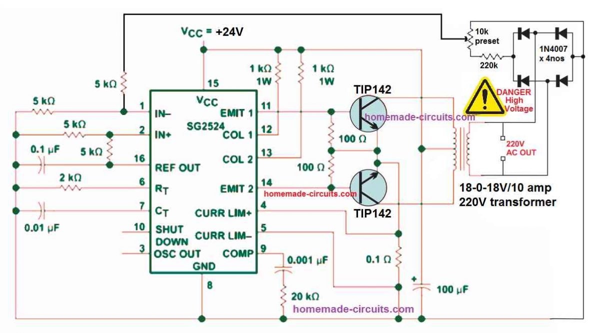
The first example circuit belw shows how an automatic feedback control can be added to a SG2524 inverter circuit. The same concept can be also applied to all the other inverter versions, using the IC SG3524, and SG3525.
You can refer to the following two datasheets for exactly knowing how the pinouts of the IC SG2524 IC are designed to function:
The feedback control loop is configured in the following can be understood with the following points:
The 220V AC output is first rectified using a 4 diode bridge rectifier circuit.
The rectified high voltage DC is dropped to a lower DC level, at around 5V to 10V through the voltage divider network built using the 220K resistors and the 10K preset.
The 10K preset is used to adjust the feedback voltage until the output voltage is controlled just at the right level.
The feedback is taken from the 10K preset's center arm and fed to the error amplifier's non-inverting input pin#1 of the IC 2524.
This error amplifier is nothing but an opamp set internal to the IC for controlling the PWM of the output pin#11 and Pin#14.
The inverting or the (+) input pin#2 of the op amp is clamped at a fixed reference level of +2.5V through the couple of voltage divider resistors configured around the pin#2 and pin#16 of the IC. The +5V reference potential is derived from pin#16 of the IC and then dropped to 2.5V using the two voltage divider resisters.
Since the pin#2 of the error amplifier is fixed at 2.5V reference, means that if the pin#1 of the opamp rises above the 2.5V level would instantly trigger the PWM feature of the IC, causing narrowing of the output PWM to the transistors.
The feedback 10k preset is adjusted in a such a way that feedback voltage at pin#1 reaches the 2.6 V mark as soon as the output voltage reaches the specified unsafe high voltage level.
In such situations, when the pin#1 receives a 2.6 V, it will cause the internal error amp to activate, narrowing the output PWMs to the transistors, which will in turn cause the output voltage to reduce to the safe lower levels, appropriately.
Simple Voltage Feedback Control for SG3525 Inverters
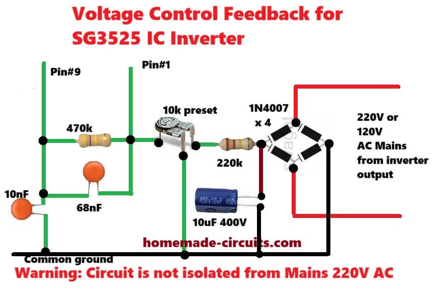
This is simple non isolated direct feedback circuit for SG3525 inverter. First high voltage 220 AC comes from inverter output. Then four 1N4007 diodes convert this AC into DC.
After that 220k resistor drops high voltage and 10uF four hundred volt capacitor smooths out DC ripple. Now 10k preset is used as voltage divider to set output voltage to220 or 120 volt. Sampled voltage directly goes to Pin number one of SG3525 IC.
Between Pin number 1 and Pin number 9 there is 470k resistor and 68nF capacitor network for error amplifier compensation to stop oscillation.
Also 10nF capacitor is connected from Pin number 9 to ground for extra filtering. When output AC voltage increases, voltage at Pin number 1 also goes up.
Since Pin 2 is supposed to be at fixed reference, high voltage at Pin 1 forces internal error amp to reduce duty cycle and output voltage comes back to normal level.
Main warning is that this whole circuit shares common ground with AC output, so it is not isolated and touching any part can give dangerous electric shock.
Adding Feedback in IC 555 Inverter
You might have already gone through the post which explains how to build simple 555 based inverters.
Although all these inverters are decently designed and will produce the intended 220 V or 120 V from an easy IC 555 set up, these do not have a built-in feedback system for ensuring a constant output voltage.
The following figure shows how an ordinary IC 555 inverter could be transformed into an enhanced inverter through an easy feedback loop control network.
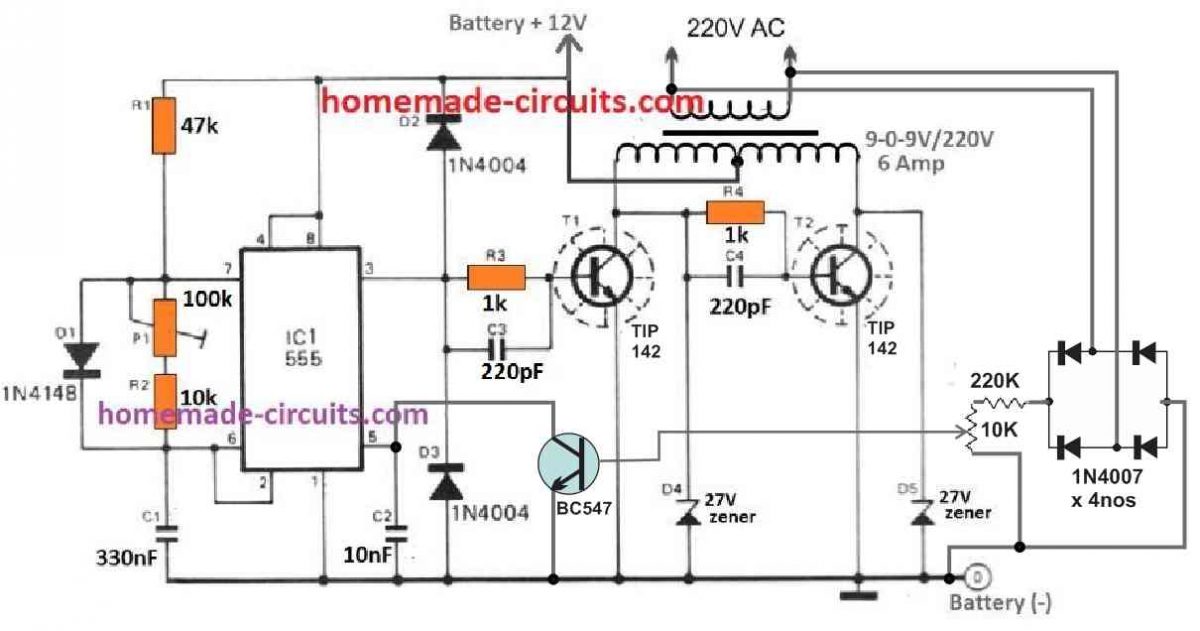
In this circuit also, we find that the 220V output from the transformer is first rectified to a DC level, and then it is stepped down through a resistive network comprising of a 220K resistor and a 10k preset.
The 10k preset center lead is configured with the NPN transistor BC547, whose collector can be seen connected with the pin#5 of the IC which is control input of the IC.
We know that normally when pin#5 is open, the PWM at the output pin#3 of the IC has a maximum PWM, however, as the potential at pin#5 is reduced, the output PWM also gets reduced proportionately.
Grounding the pin#5 causes the output PWM at pin#3 to become very narrow, with almost zero average voltage at this pinout.
In the IC 555 feedback circuit, when the output voltage tends to rise above the unsafe high voltage threshold, as per the setting of the 10k preset, the base of the BC547 slowly starts getting biased. When this happens, the BC547 begins conducting and causes the pin#5 of the IC to get gradually grounded. The grounding of the pin#5 of the IC causes the output PWM at pin#3 to get narrower, which in turns causes the output voltage to drop to the normal levels.



Questions & Answers
Good job sir,your unrelenting effort is of great help to us.
It is my pleasure Evans!
Hello sir Swagatam good afternoon. I have a circuit inverter from his website, the circuit is modified sine wave with lm555 timer and cd4017. The question is.. How can I add to that circuit this circuit with feedback control. Thanks you so much
Hello Carlos, is the diagram from the following article:
https://www.homemade-circuits.com/modified-sine-wave-inverter-circuit-2/
did you use the second diagram??
Hello, No sir, I used the number 1
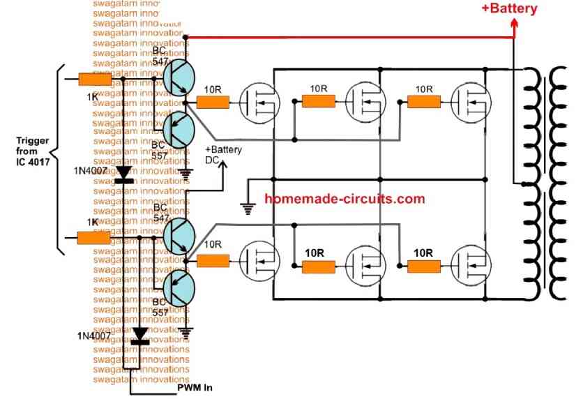
Carlos, you can try the the following modification for the feedback control
Thanks Swag for this article, but how can I incorporate the overload shutdown to my sg3524 module.
Hi Seun, please see the pin4 and pin5 configuration with the 0.1 Ohm resistor. This resistor value decides the overload or over current shut down.
Please sir, how do calculate the resistor per load
You can use the following formula
R = 0.2 / Load current limit
Sir, God bless you for really coming up to each of my questions.please sir, I have some few questions which are:1 the above sg2524 inverter circuit,at the output, do you need to filter out the ripple signal? Because is not a smooth dc output, and if yes then what value? secondly,I want to cut off for my inverter at a power rating of 1000w,due to the formula in some of your feedback to bro.seun.sir,I calculated it and it was R=0.0024,am using 12v battery and load current of 83.3amp.so how many 0.1ohm resistor do I need a connect in parallel? thanks sir.
Thanks Eniola, to tackle the ripple you can add a 2200uF capacitor right across the battery terminals, and also a 100uf right across the IC supply pins.
For calculating the number of 0.1 ohm resistors you can use a parallel resistor formula….please use the formula or you can try any online resistor calculator software to get the approximate value of the resistors.
Please sir, how can I calculate the resistor in parallel? Or is it 1/R=1/r1+1/r2+1/r3…… orJust give me the formula sir. But if it is the above formula ostensibly,I will parallel about 10 of 0.1ohm resistor for 1000w cut off.but if not just introduce me the appropriate formula.thanks sir, looking forward to your quick reply
Eniola, you can use the mentioned formula for calculating the number of parallel resistors with some manipulation. You can put 0.1 for R1, R2, R3…and check how many resistors are required to get close 0.0024…then further use the result with the parallel formula to get the precise value.
You can online calculators also
Please how can I add low battery shutdown circuit to #10 to latch, the design I have personally cut off but comes up when the battery voltage rises
You can add the following op amp design with the first circuit for the low battery cut off:
Thanks Sir, please how can use this for 48v input
Hi Seun, you can drop the voltage to 12V for powering the IC through a 4k7 1 watt resistor, and a 12V zener diode.
Please sir, what adjustment can I do to work with 48v input.
Thanks sir, please is there any alternative to using pin 16, the board is already plastered. Swagatam, help out
Pin16 gives the 5V reference to the op amp, if you don’t want the reference from pin16, you can create it using an external 1K resistor, and a 5V zener diode.
Thanks Sir for your assistance, I have tried both ways, they cut off but didn’t latch, any help.
I guess it won’t latch, instead it will cause the output PWM to become minimal so that the battery usage becomes negligible for the load
Please Sir, how can I have low battery cut that will shut down and latch for Sg3524 circuit
Seun, you can use the following modification for latching the inverter during low battery voltage
Please sir the op amp low battery you posted in your comment section, 1. Sir please how can i adjust the cutt off voltage manually using the 10k preset without variable or bench power supply?
2. Is it the above circuit applicable to 12v system using Sg3524 ic.
Thanks for your response in advance.
Godspower, you will need to feed the circuit supply lines with the low voltage at which you want the cut off to happen. Initially rotate the preset wiper upto the positive supply rail. Then switch ON the low voltage supply, and adjust the preset until the output of the op amp just turns high and the LED illuminates.
yes it is applicable to 12V supply
Mr Swag i am very greatful sir for this quick response God in heaven will continue to bless you.
please sir do not be annoyed because of my questions as i am an electronics hobbyist and i have built my inverter am currently using , please one more question sir.
I built my 12volt battery using lithium ion battery but no Bms, but base on my research i discovered that the maximum full voltage is 12.6v, now i want the battery to be discharged up to 9v since am personally using the battery. question sir
1. Is it possible to adjust the above circuit to cut off at 9v?
2. Advice me on the minimum voltage to discharge from the battery?
Hello Godspower, you must adjust the preset for a 10V low battery cut off, meaning, if the supply reaches 10V, the opamp output will become high, and if the voltage increases above the 10V, for example if the voltage is 10.2V then the opamp output will become low.
Hi sir, I want to add a low battery cut off at 11v, imitating your low battery cut off circuit.sir, I want to cut off at 11v and I think for it to cut off at 11v the pin 3 has to be set at a constant voltage of 11v and the pin 2 will be set at,let me use 12v,as the battery voltage get utilized the voltage at pin 2 start to drop on till it gets to 11v which will trigger the opamp output high.since the ic is employ as a comparator.im I right? If right please,just give me resistor value to implement that.or just give me the formula for voltage drop by resistor with the current.
Eniola, that’s right, however instead of using fixed resistors you must use a preset at pin#2, so that the exact 11V cut off can be adjusted, as implemented in the SG3535 circuits:
https://www.homemade-circuits.com/sg3525-pure-sinewave-inverter-circuit/
Thank you sir for the circuit. sir please please what is the frequency of the above circuit for sg3524 and Ic 555
You are welcome Godspower, the frequencies should be around 50 Hz, but for the IC 555 you will have to tweak using the 100k preset.
Thank you sir for the quick response sir.
Please sir from the Sg3524 circuit above, i could not find the following resistors, 5k, 2k, 20k, please sir is it posible for me to replace 5k with 4k7? and connect (2) 1k in series and (2)10k in series to give me 2k and 20k repectively? Thank you sir God bless you sir.
You are welcome Godspower, yes definitely all those options are possible, no problems with that.
Thank you so much sir very grateful
Thanks a lot sir. I was so impressed that you are helping us here and also responding swiftly and well. Thanks so much sir.
You are welcome!
very nice article
Good day mr swag
pls do u have any article
of how to make an inverter without using an ic and of about 50HZ-60HZ speed to switch on/off
Hi Martin, you can try the following diagram:
https://www.homemade-circuits.com/how-to-make-simple-200-va-homemade/
1-CAN MOSFET IRF3205 BE USED INSTEAD OF TRANSISTOR
2-HOW CAN INCREASE THE WATTAGE OF THE OUTPUT
1) Yes it can be used.
2) Wattage can increased by implementing the steps explained in the following article:
https://www.homemade-circuits.com/upgrading-low-power-inverter-to-high/
GOOD DAY SIR
PLS DO U HV ANY ARTICLE OF AN INVERTER THAT CAN GIVE AN OUTPUT OF 7.5KVA AND HOW CAN INCREASE THE OUTPUT… THANKS IN ADVANCE, WAITING FOR UR REPLY
Hello Ebuka, you can refer to the following articles for learning the procedures:
https://www.homemade-circuits.com/upgrading-low-power-inverter-to-high/
https://www.homemade-circuits.com/how-to-calculate-and-match-inverter/
Hi sir
can i connect 470ohm + 100ohm resistor to use as 560ohm
Sure, you can do that!
HI SIR
THANKS FOR UR PREVIOUS REPLY
PLS AM A BIT CONFUSED ABOUT SOME ELECTRICAL PART PLS WHEN U WROTE 1K RESISTOR DID U MEAN 100ohm
(2)DID U HAVE AN ARTICLE DAT CAN POWER ELECTRIC IRON
Hi Martins, please specify the comment reply which you are referring to?
All inverter circuits can be used for powering an electric iron provided they are upgraded as per the iron wattage..
I MEAN IN THE PLACES U WROTE 1K RESISTOR DO U MEAN 100 ohm