The cost and quantity of parts necessary to develop the proposed 250 watt sine wave power inverter circuit is actually much less compared to a noisy square wave switching-type inverter circuit.
Only an extra three or four tiny transistors, a some resistors and capacitors, a couple of pots and a small driver transformer are all the additional parts which are required.
A glance at the block diagram will be enough to indicate that the fundamental concept of this sine wave power inverter is extremely basic.
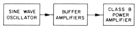
The block diagram matches one of the simple 80 meter CW transmitter circuit. Essentially, it is only the frequency that is different ; 60 Hz instead of 3.5 MHz. And producing 250 watts of sine wave ac actually becomes drastically easier with the 500,000 meters (60 Hz) as opposed to the 80 meters (3.5 MHz).
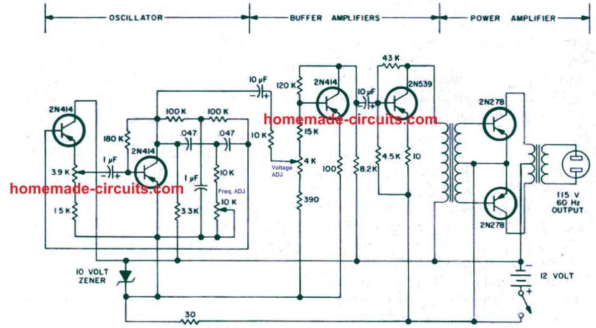
A complete circuit diagram of the 250 watt sine wave inverter is shown below. The requirements are a sine wave oscillator, a buffer amplifier, and a power amplifier.
The Oscillator
The oscillator could be in fact of any variety, however your best option for sensible reasons can be one particular implementing RC combinations.
Actually an oscillator involving inductor-capacitor combination as for example in the Hartley or Colpitts oscillator circuits could be incorporated at 60 Hz.
However the difficulty of adjusting the frequency to be able to adapt it to 60 Hz happens to be greatly simplified by utilizing an oscillator which has its frequency implemented using an RC network. The frequency now could be altered by simply adjusting a potentiometer.
Referring to the circuit diagram, here the 10K potentiometer in the oscillator stage permits us to adjust the frequency. Do not forget that the oscillator stage will create a sine wave.
Several RC oscillator circuits are usually built to generate square waves while some others generate a sawtooth output.
We don 't want to employ these types, simply because we may end up with an inverter which is may be a low quality modified inverter. The 3.9K potentiometer in the oscillator section is positioned to regulate the level of gain in the feed back loop. Very high gain setting using this pot might lead to extreme distortion of the sine wave.
Setting the Frequency
How could you set the oscillator frequency to 60 Hz? You can use just about any common methods for computing, just like an audio frequency is measured . You could possibly evaluate your oscillator's frequency with the mains utility line voltage frequency either by seeing Lissajous statistics with an oscilloscope or by listening to and setting the beat frequency to zero.
Or perhaps for those who have a digital frequency counter, that' the best option you can have, so use it to measure and set the frequency to 60 Hz.
Output Voltage
Besides getting the frequency correct , you should have the output voltage fairly close to the preferred range of 115 - 120 volts (or to 220V depending on the transformer). As indicated in the circuit diagram the output voltage is dependent on the adjustment of t he 4 K potentiometer which can be seen situated between the oscillator and the buffer amplifier stages.
A simple way to measure and confirm the output volts is by using a standard DMM set to the AC 500 V range and then measure the output voltage while simultaneously adjusting the 4 K pot.
Transformers
In this stage the both the transformers are ordinary 60 Hz step down transformers. The driver transformer, for instance is actually a tiny power transformer having about three filament windings.
One winding may be employed for the primary , and the remaining two in series might be used for creating the center tapped secondary.
A very common type center-tapped filament transformer could be very much appropriate for the output power transformer. With a 12 volt battery supply, you might anticipate the power amplifier transistors to generate an ac voltage of around 7-9 volts peak value or 5 to 6.5 volts rms.
It means that a 12 volt center-tapped filament transformer rated at 115 volt secondary winding output must be pretty sufficient.
The dimensions or current rating of the filament transformer depends upon the total power output you would want to generate.
A 25 ampere, 12V transformer is going to be pretty enough for generating power outputs up to 200 to 250 watts. Picking out the transistor type in the power amplifier stage also will be dependent mainly by simply how much output power you want to generate.
Waveforms
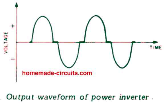
The true waveform that can be acquired from this 250 watt sine wave inverter is slightly different from a true sine wave. As indicated in the above figure, each power transistor of this power inverter amplifier comes with an operating angle marginally lower than 180λ , that is certainly, near to a Class C type working.
A little deviation in the biasing of the transistors might pull the amplifier back to genuine Class B, however because no noises can be seen developing, this further hard work to improve the bias doesn't appear to be useful.
Simple 250 Watt, 50 Hz Square Wave Inverter Circuit
This 250 watt inverter configuration employs a regular mains transformer in reverse to generate an output of approximately 220VAC operating at around 50Hz. For this purpose, a toroidal transformer, such as the I LP 30VA model, is suitable.
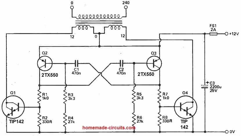
The secondary side of the mains transformer is driven by Darlington power transistors using a 50Hz square wave.
These transistors are equipped with internal anti-parallel diodes that catch any spikes resulting from leakage reactance.
If individuals intend to create their own Darlingtons using discrete transistors, it's necessary to incorporate diodes with their cathodes oriented towards the transformer to fulfill this function.
A conventional multivibrator is responsible for supplying the base drive to the power transistors. The specified component values are designed for operation slightly above 50Hz.
Opting for a slightly higher frequency is advisable due to the risk of transformer saturation at lower frequencies.
Careful consideration of Q2 and Q3 is crucial to ensure reliable circuit operation, especially considering its substantial load. While BC212 transistors might work in some scenarios, this cannot be guaranteed.
Reliable functioning of this 250 watt inverter circuit hinges on maintaining short connections between the transformer center tap, the power transistor emitters, and C3.


Questions & Answers
Dear Mr Swagatam
Can I replace 2N414 with BC547,
2N414 is hard to find in my country.
Hi, Poloko,
You can try BC557 instead.
If I want to make 300 watt pure sine wave, what components do I need to change?
You only need to upgrade the output transistors and the transformer appropriately for handling 300 watts.
What is the Ah battery rated or suitable for the inverter?
Battery can be 200 Ah.
I love this site it’s well explained.
Turn’s ratio of the first and the second transformer please. What is the maximum input of the first transformer?
The first transformer can be a 3-0-3 / 220V 500 mA transformer and the second one can be a 9-0-9V/220V 5 amp transformer
Hello Mr, i see two transformers, can you please clarify the function of the first one. I guess the second one is a power transformer.
Besides that can i replace the power transistors with the igbt? If possible how would it look like? Aim is 5kw.
The first transformer is driver transformer for the power transistors.
I don’t think IGBTs will work in this design.
This design is suitable for small model inverters only.
Mr swagatan qua o limite de potência ou qual a potência máxima que ele pode alcançar quais as melhorias que posso fazer ? Espero sua resposta por favor
Hello Raimundo,
Maximum power will depend on the power capacity of the two output transistors, transformer and the battery. In the presetnt design it is around 250 watts.
Sir thanks for your support on all your posts I’m grateful. Pls sir can you help me with an advanced pure sine wave inverter circuit design? I will be very glad if given this circuit. Sir I need this for my house and I think 1500w is ok
Thanks Chris, you can probably try the following easy to build concept:
https://www.homemade-circuits.com/1500-watt-pwm-sinewave-inverter-circuit/
For the mosfets you can use 4 nos of IRFP2907 in parallel
Hello Mr swagatam says how about replacing 2N278 with 2sc5200 for high power output? Thanks in advance looking forward hearing from you.
Hi Poloko, yes you can definitely do that, you can replace the output transistor with other powerful versions to get a more powerful output.
Hi sir I have constructed the circuit and it worked but having challenge with its upgrading. Most of the components are not available here so I used other transistors(2n5401 and 2n5551) at the driver stage but output drops when load is applied to the circuit. pls can you help me with a sinewave circuit that uses mosfets ?
Hi Chris, thanks for updating the results. You can upgrade the power output by replacing the output transistors (2N278) with high power transistors such as TIP36. Along with this you will also have to upgrade the output transformer and the battery appropriately.
Hello sir what is the precise driver transformer 12v or 6v center tap because the voltage switching the output transistor should be around 4.5 to 6v. Pls assist me.
Hello Chris, if the output is switching at 6V RMS, then you can use a 6-0-6 center tap output transformer.
Pls sir can we use a normal transformer In this inverter and also how can we increase the wattage output. Thanks and look forward to hearing from you.
Anthony, you can use any ordinary step down transformer in the above circuit….to increase wattage, increase current rating transformer and battery, and the output transistors.
I like this circuit but have a boubt about driver transformer can we use ordinary transformer step down
yes, driver transformer can be any small step down transformer!
Pls the capacitor 1uf hooking 100k resistors. Pls is polarized or non polarized.
I would recommend a non-polar capacitor
Thanks Swagatam. Pls is the circuit a pure sine wave? and can I use MOSFET at output stage?
You are welcome Chris, it is a pure sine wave, but mosfets might not work perfectly at the output stage….
Any pics of the final layout pcb,pics of transformers to use?
It was take from an old electronic magazine, which did not include the practical images.
I am required pure sine wave ups circuit diagram