This calculator is basically finding out two things:
- How much capacitor (C) you should put in series with.
- What value resistor (R) to use in series with that capacitor,
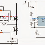
...so that we can make a perfect RC snubber for killing high voltage spikes across:
- MOSFETs (especially in H-bridge and inductive loads)
- TRIACs (AC switching spikes)
- Relay contacts (spark arrestor)

Now let us break down everything it’s calculating.
RC Snubber Calculator
Basic Snubber Formula Logic
There are two formulas used here:
1. To Calculate Capacitor:
We use this:
C = (I × tr) ÷ VWhere:
| Symbol | Means |
|---|---|
| C | Capacitance in Farads |
| I | Peak current in Amps |
| tr | Voltage rise time (in seconds) |
| V | Peak voltage across the switch |
This formula comes from the charge equation Q = I × tr and Q = C × V → so C = I × tr ÷ V.
2. To Calculate Resistor:
We use:
R = 1 ÷ (2 × π × f × C)Where:
| Symbol | Means |
|---|---|
| R | Snubber resistor in Ohms |
| f | Approx frequency (here fixed 50kHz) |
| C | Capacitance calculated above |
This is the classic damping resistor formula for snubbers (derived from RC time constant).
Real Example Calculation (Manual)
Let us say we are using this for a MOSFET switching a motor, and we have:
- Peak voltage across drain-source:
220V - Peak current:
5 Amps - Rise time of voltage spike:
1 µs(that is 1e-6 sec)
Step 1: Calculate Capacitance
C = (I × tr) ÷ V
C = (5 × 1e-6) ÷ 220
C = 0.000005 ÷ 220 = 2.27e-8 F = 22.7 nF
So you need a 22.7 nF capacitor (you can round to 22nF or 33nF for standard values)
Step 2: Calculate Resistor
We assume switching frequency is around 50kHz so:
R = 1 ÷ (2 × π × 50000 × 22.7e-9)
R ≈ 1 ÷ (0.00713)
R ≈ 140 Ohms
So you can use a 150 Ohm resistor, 1W or 2W rated (metal film or carbon film).
Notes on Capacitor Selection
- Use Polyester (MKT or MKP) or X2 film capacitors.
- Voltage rating must be minimum 2x your working voltage.
- So for 220V use 400V or 630V cap.
- Do not use electrolytic caps in snubbers.
Notes on Resistor Selection
- Resistor must dissipate the energy dumped by the cap
- Use at least 1W or 2W metal film resistor
- Avoid wire-wound types (can be inductive)
Application Selector Meaning
| Type Selected | Implication in Real Use |
|---|---|
| MOSFET | For DC motor H-bridges, boost converter, buck converter, etc. |
| TRIAC | For AC switching with inductive load (like fans, transformers) |
| RELAY | For sparking at mechanical contacts during coil turn off |
All three use the same formulas, just the waveform nature is different.
Summary
- We first see how big the spike is (voltage), how fast it rises (rise time), and how much current flows.
- Then we use that to calculate a cap that can suck in that surge.
- Then we calculate a resistor so that this capacitor can safely burn out that energy slowly without making smoke.
- Finally we show the values in nanoFarads and Ohms so we can pick easy available parts.
What is Rise Time Actually?
Rise time (we call it tr) is how fast the voltage spike rises across the switch (MOSFET, TRIAC, relay contact) when it turns off.
It is the time taken for the voltage to go up from 10% to 90% of its peak level.
So if a spike goes from 0V to 220V, rise time means how long it took to go from 22V to 198V.
What If We Don’t Have Oscilloscope to measure it?
In hobby world we can only assume or estimate it based on the application and switching type. Below is a cheat sheet.
Rough Rise Time Estimates (No Tools Needed)
| Application Type | Rise Time to Use (tr) | Notes |
|---|---|---|
| Low-frequency relay contacts | 10 ms (0.01 sec) | Big arcs, slow contacts |
| TRIAC AC loads (like fan, lamp) | 100 µs (0.0001 sec) | AC zero crossing turn-off |
| MOSFET switching SMPS or motor | 1 µs (0.000001 sec) | Fast switching |
| High-speed IGBT or GaN FET switching | 100 ns (0.0000001 sec)` | Super fast, high-end systems |
So:
- For relays use 10ms (if you hear click sound, that means slow!).
- For TRIAC dimmer or AC switch, use 100µs.
- For basic 12V DC MOSFET circuits, assume 1µs.
- If using high-speed driver + small load, assume 100ns.
If hobbyist has no idea, then they may use a safe default of 1 µs:
tr = 0.000001 secRise Time Depends On...
- Driver strength (weak gate driver = slower).
- MOSFET capacitance (high Cgs = slower).
- Load type (inductive loads = faster transients).
- Supply voltage (high voltage = sharper edges).
So guys, if you are switching small 12V fan, then rise time can be 5µs or more.
If you are switching high-voltage inverter with IR2110, then rise time might be <1µs.


Questions & Answers
Hello
Can you please support me to design a snubber. My application is to drive BLDC fans 10*1.9 A by a 24V DC supply, Provided the PWM controller works on 25kHz switching.
Sure, please try this:
You can use a simple RC snubber across the MOSFET drain and source. Start with a 47nF capacitor (@ 100V rating) in series with a 22Ω resistor (2W or higher). Since your PWM is 25kHz, so the snubber will help suppressing switching spikes and ringing due to wiring inductance and the fan load.
After building, please try to check the waveform on an oscilloscope to adjust the values further. If spikes are still high, increase the capacitor slightly. If ringing is present, then fine-tune the resistor value.
Also you can consider adding a 33V TVS diode across the supply for extra protection.
hi sir, sir peak current is depends on mosfet, relays, triac. or load?
Hi Ghulam, peak current depends on the load specifications…
i would like to use resistors in parallel
resistors are 2,5,10 ohms and 500 watts each
can i use same snubber for IGBTS as a smirch instead of MOSFET
THE RESISTORS ARE WORE WOUNF, NON-INDUCTIVE WATER COOLED
THANKS
ARVIND
Yes, identical snubbers can be used for both MOSFETs and IGBTs.
500 watt resistors are not required…just 5 watt should be enough…
I AM WORKING ON PROJECT TO DESIGN
INDUCTION HEATING POWER SUPPLY
RATING =100 KW
FREQUENCY: 10 KHZ OR 25 KHZ
INPUT 3 PHASE, 480 V , 60 HZ
INVTER: SINGLE PHASE 265V OUTPUR, 500 AMPS
I NEED TO KNOE GUIDELINE TO DESIGN RC SNUBBER FOR THIS
SWITCHING IS ACCOMPLISHED THROUGH IGBT
COULD YOU PEASSE HELP ME ON THE ABOVE
THANKS
ARVIND
R = 2 ohm, made from 10 nos of 0.2 ohm 1/4 watt in series.
C = 1uF/1000V or 2000V PPC or MKT