Today we are going to discuss a purely analog high voltage protection circuit which is specially designed for solar power systems working with PV voltages from around 90 volts up to 400 volts DC.
The main purpose of this circuit is to disconnect the inverter whenever the solar panel voltage falls below a safe level, like below 90V, so that the inverter is protected from low voltage brownout conditions.
The entire circuit is fully solid state and does not use any mechanical relay, making it much more reliable for very high voltage DC applications.
Audio/Video Reptesentation
Why Ordinary Relays Fail at 400V DC
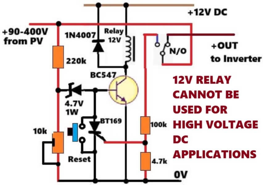
Many people try to use ordinary 12 volt mechanical relays for disconnecting a 300 volt or 400 volt DC supply, but this normally creates a serious problem.
Unlike AC, a high voltage DC supply never passes through a zero crossing point. Because of this, when the relay contacts try to open under load, then a powerful electric arc develops between the contacts.
This arc can continue burning until the contacts become welded together or the relay gets permanently damaged. In many cases the arc can also create excessive heat and damage nearby components on the control board.
Using a MOSFET Instead of a Relay
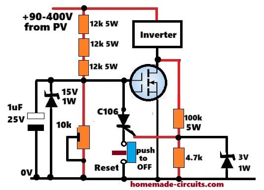
To avoid all these problems, this circuit uses a high voltage N-channel MOSFET instead of a relay.
The MOSFET is connected on the negative line of the inverter and performs the switching electronically without producing any spark or arc.
Another important feature of this design is its automatic latching action, which is achieved with the help of a C106 SCR. Once the protection is activated, the inverter remains disconnected until it is manually reset.
High Voltage Input and Resistor Network
The circuit receives its input directly from the solar panel, where the voltage can vary anywhere between 90 volts and 400 volts DC.
The positive supply is connected directly to the inverter while a small portion of the voltage is taken for the control circuit through a resistor network. Instead of using one large resistor, the circuit uses three 12k, 5 watt resistors connected in series. Together they provide a total resistance of 36k ohms.
This arrangement allows the voltage and power dissipation to be shared equally between the resistors, so each resistor operates well within its safe power rating even when the PV voltage reaches 400 volts.
Gate Protection and Voltage Filtering
The control voltage is further stabilized with the help of a 15 volt, 1 watt Zener diode connected across the 10k adjustment potentiometer.
This Zener is a very important component because it limits the maximum gate voltage of the MOSFET to around 15 volts. Without this protection the gate oxide inside the MOSFET could easily break down if exposed to the full solar voltage.
A 1 microfarad capacitor is also connected across the control section to filter small voltage spikes and switching disturbances which may occur when the inverter starts operating.
Setting the Low Voltage Cutoff Point
The 10k potentiometer is used for adjusting the low voltage cutoff point. Under normal conditions, when the solar panel voltage is above the preset value, the voltage developed across the potentiometer is high enough to fully turn ON the MOSFET.
This allows the inverter to receive its negative supply connection and operate normally. Since the MOSFET is fully enhanced, it remains cool and avoids operating in the linear region where excessive heating can occur.
How the SCR Latching Section Works
The latching section of the circuit is connected to the drain of the MOSFET. This point is linked through a 100k, 5 watt resistor, a 4.7k resistor and a 3 volt Zener diode to the gate of the C106 SCR.
During normal operation this section remains inactive because the MOSFET drain stays close to ground potential.
What Happens When the Voltage Falls
As soon as the solar panel voltage falls below the preset limit, the gate voltage of the MOSFET starts reducing and the MOSFET begins turning OFF.
As the MOSFET switches OFF, its drain voltage quickly rises towards the full PV supply voltage. This sudden voltage rise is fed through the resistor network to the gate of the SCR, instantly triggering it into conduction.
How the Inverter Gets Disconnected
Once the SCR turns ON, it immediately pulls the MOSFET gate to ground through the normally closed manual reset switch.
This action forces the MOSFET to switch completely OFF, disconnecting the inverter from the solar supply without any oscillation or repeated switching. The inverter remains safely isolated from the low voltage solar source.
Why the Circuit Stays Latched OFF
Even after the initial trigger pulse disappears, the SCR continues conducting because it receives a small holding current through the 36k resistor network.
At the minimum operating voltage of around 90 volts, this holding current is sufficient to keep a sensitive SCR such as the C106 or BT169 latched in the ON state.
As a result, then inverter cannot restart automatically even if the voltage fluctuates around the cutoff level.
Manual Reset Operation
To restore normal operation, the user has to press the manual reset push button. This temporarily interrupts the SCR holding current, allowing it to switch OFF.
If the solar panel voltage has already recovered above the preset threshold, then MOSFET gate once again receives the required drive voltage, the MOSFET turns ON, and the inverter starts operating normally.
Conclusion
This circuit provides a simple but highly effective low voltage protection system for high voltage solar installations. Since it uses only analog components, it does not require any programming, firmware or microcontroller. The absence of mechanical relays also removes the danger of contact arcing, making the design highly suitable for PV systems operating with voltages as high as 400 volts DC.



Need Help? Please Leave a Comment! We value your input—Kindly keep it relevant to the above topic!