In this article I have explained 10 simple automatic emergency light circuits using high bright LEDs. This circuit can be used during power failures and outdoors where any other source of power might be unavailable.
What's an Emergency Lamp
An emergency light is a circuit which automatically switches ON a battery operated lamp as soon as the mains AC input is unavailable or during mains power failure and outages.
It prevents the user from being into an inconvenient situation due to sudden darkness, and helps the user to get access to an instant make shift emergency illumination.
The discussed circuits uses LEDs instead of incandescent lamp, thus making the unit very power efficient and brighter with its light output.
Moreover, the circuit employs a very innovative concept especially devised by me which further enhances the economical feature of the unit.
Let’s learn the concept and the circuit more closely:
Warning: A few circuits I have explained below, without using transformer are not isolated from mains AC, and therefore are extremely dangerous to touch in the powered and open condition. You should be extremely careful while building and testing these circuits, and make sure to take the necessary safety precautions. The author cannot be held responsible for any mishap due to any negligence by the user.
Automatic Emergency Light Theory
As the name suggests, it is a system that automatically switches ON a lamp when regular AC supply fails, and switches it OFF when mains power returns.
An emergency light can be crucial in areas where power outage is frequent, as it can prevent the user from going through an inconvenient situation when suddenly mains power shuts down. It allows the user to continue with the ongoing task or access a better alternative such as switching ON a generator or an inverter, until mains power is restored..
1) Using a Single PNP Transistor
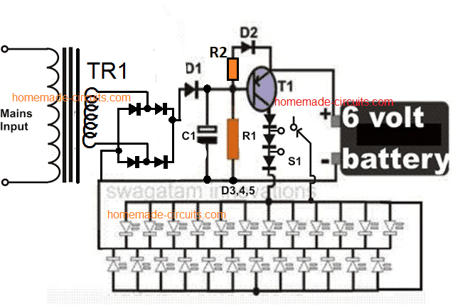
The concept: We know that LEDs require a certain fixed forward voltage drop to become illuminated and it is at this rating when the LED is at it’s best, that is voltages which is around its forward voltage drop facilitates the device to operate in the most efficient way.
As this voltage is increased, the LED starts drawing more current, rather dissipating extra current by getting heated up itself and also through the resistor which also gets heated up in the process of limiting the extra current.
If we could maintain a voltage around an LED near to its rated forward voltage, we could use it more efficiently.
That’s exactly what I have tried to fix in the circuit. Since the battery used here is a 6 volt battery, means this source is a bit higher than the forward voltage of the LEDs used here, which amounts to 3.5 volts.
The extra 2.5 volts rise can cause considerable dissipation and loss of power through heat generation.
Therefore I employed a few diodes in series with the supply and made sure that initially when the battery is fully charged; three diodes are effectively switched so as to drop the excess 2.5 volts across the white LEDs (because each diode drop 0.6 volts across itself).
Now as the voltage of the battery drops, the diodes series are reduced to two and subsequently to one making sure only the desired amount of voltage reaches the LED bank.
In this way the proposed simple emergency lamp circuit is made highly efficient with its current consumption, and it provides backup for a much longer period of time than what it would do with ordinary connections
However, you can remove those diodes if you don't want to include them.
Circuit Diagram
How this white LED Emergency Light Circuit Works
Referring to the circuit diagram, we see that the circuit is actually very easy to understand, let’s evaluate it with the following points:
The transformer, bridge and the capacitor forms a standard Power supply for the circuit. The circuit is basically made up of a single PNP transistor, which is used as a switch here.
We know that PNP devices are referenced to positive potentials and it acts like ground to them. So connecting a positive supply to the base of a PNP device would mean grounding of its base.
Here, as long as mains power is ON, the positive from the supply reaches the base of the transistor, keeping it switched off.
Therefore the voltage from the battery is not able to reach the LED bank, keeping it switched off. In the meantime the battery is charged by the power supply voltage and it’s charged through the system of trickle charging.
However, as soon as the mains power disrupts, the positive at the base of the transistor disappears and it gets forward biased through the 10K resistor.
The transistor switches ON, instantly illuminating the LEDs. Initially all the diodes are included in the voltage path, and are gradually bypassed one by one as the LED gets dimmer.
HAVE ANY DOUBTS? FEEL FREE TO COMMENT AND INTERACT.
Parts List
- R1 = 10K,
- R2 = 470 ohms
- C1 = 100uF/25V,
- Bridge diodes and D1, D2 = 1N4007,
- D3---D5 = 1N5408,
- T1 = BD140
- Tr1 = 0-6V, 500mA,
- LEDs = white, hi-efficiency, 5mm,
- S1 = switch with three changeover contacts. Using Transformerless power supply
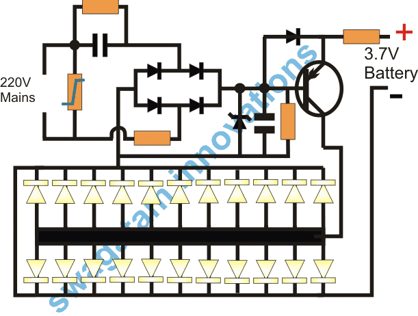
The design presented above can be also made using a transformerless supply as shown below:
Here I will elucidate how an emergency lamp can be build without a transformer using a some LEDs and a handful of ordinary components.
The main features of the proposed automatic transformerless emergency light circuit is though very identical to the earlier designs, the elimination of the transformer makes the design pretty handy.
Because now the circuit becomes very compact, low cost and easy to build.
However, the circuit being completely and directly linked with the AC mains is hugely dangerous to touch in an uncovered position, so it is obvious that the constructor implements all the due safety measures while making it.
Circuit Description
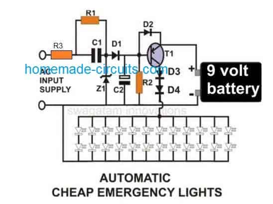
Coming back to the circuit idea, transistor T1 being an PNP transistor tends to remains in switched OFF condition as long as AC mains is present across its base emitter.
Actually here the transformer is replaced by the configuration consisting of C1, R1, Z1, D1 and C2.
The above parts constitute a nice little compact transformerless power supply, capable of keeping the transistor switched OFF during mains presence and also trickle charges the associated battery.
The transistor reverts to a biased condition with the help of R2 the moment AC power fails.
The battery power now passes through T1 and lights up the connected LEDs.
The circuit shows a 9 volts battery, however a 6 volt battery may also be incorporated, but then D3 and D4 will need to be completely removed from their positions and replaced by a wire link so that the battery power is able to flow directly through the transistor and the LEDs.
Automatic Emergency Light Circuit Diagram
Video Clip:
Parts List
- R1 = 1M,
- R2 = 10K,
- R3 = 50 ohm 1/2 watt,
- C1 = 1uF/400V PPC,
- C2 = 470uF/25V,
- D1, D2 = 1N4007,
- D3, D4 = 1N5402,
- Z1 = 12 V/ 1Watt,
- T1 =BD140,
- LEDs, White, High Efficiency, 5mm
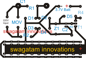
PCB Layout for the above circuit (Track side view, Actual Size)
Pats List
- R1 = 1M
- R2 = 10 ohm 1 watt
- R3 = 1K
- R4 = 33 ohm 1 watt
- D1---D5 = 1N4007
- T1 = 8550
- C1 = 474/400V PPC
- C2 = 10uF/25V
- Z1 = 4.7V
- LEDs = 20ma/5mm
- MOV = any standard for 220V application
PNP BJT Current Flow
In a PNP transistor we see that current flows from the emitter to the collector when the transistor is in its "on" state. The base current which we call IB plays a crucial role in controlling how much current flows through the collector-emitter path.
Emitter Current (IE)
The current that comes out of the emitter is related to both the collector current and the base current. We can express this relationship with the formula:
IE = IC + IB
Where:
- IE is the emitter current.
- IC is the collector current.
- IB is the base current.
Collector Current (IC)
When we are in the active region the collector current is dependent on the base current through what we call the current gain (β) of the transistor. This can be written as:
IC = β * IB
Where:
- IC represents the collector current which is also the current flowing through any LED load we have connected.
- β is the current gain (also known as hFE) of the PNP transistor and it usually ranges from about 100 to 300.
- IB is again our base current.
Base Current (IB)
To figure out the base current we can use the input voltage along with the base-emitter voltage (VBE). The formula looks like this:
IB = (Vin - VBE) / RB
Where:
- Vin is the voltage we apply to the base.
- VBE is the base-emitter voltage which is typically around 0.7V when our transistor is turned on.
- RB is the base resistor that helps limit how much base current flows.
LED Load Current
Now if we assume that our LEDs are connected in the collector circuit we can relate the current through these LEDs to both the voltage drop across them and the collector-emitter voltage. The LED current can be expressed as:
ILED = (VCC - VCE) / RLED
Where:
- VCC is the supply voltage for our circuit.
- VCE is the collector-emitter voltage which should ideally be low when our transistor is fully on....typically around 0.2V or even less.
- RLED is a resistor that limits the current for our LEDs if we are using one in series.
For simplicitys sake if we assume that VCE ≈ 0V when our transistor is fully on then we can say that:
ILED ≈ VCC / RLED
Base-Emitter Voltage (VBE)
For our PNP transistor to turn on properly, we need to make sure that the base-emitter junction is forward-biased. The base-emitter voltage (VBE) for a conducting PNP transistor usually sits around 0.7V when it’s in active mode.
While this value can vary slightly depending on the specific transistor we're using, it’s generally close to that 0.7V mark.
Saturation of the PNP Transistor (V{CE(sat)})
When our PNP transistor is fully turned on or saturated, we notice that the collector-emitter voltage (VCE) drops down to a very low value, which we refer to as saturation voltage:
VCE(sat) ≈ 0.2V
This low voltage across the transistor means that most of our supply voltage gets dropped across whatever LED(s) and any current-limiting resistor we have in place.
2) Surge Protected Automatic Emergency Lamp
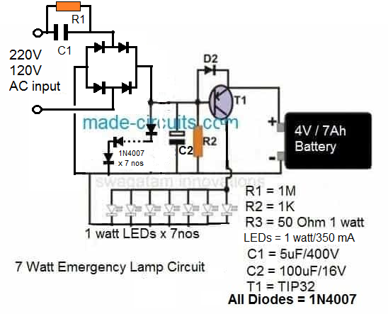
The following surge proof emergency lamp circuit employs 7 series diodes connected in forward biased condition across the supply line after the input capacitor. These 7 diodes drop around 4.9V, and thus produce a perfectly stabilized and surge protected output for charging the connected battery.
Emergency Lamp with Automatic Day Night LDR Activation
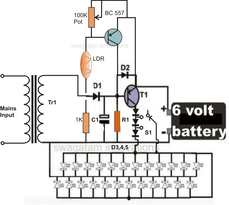
In response to the suggestion of one of our avid readers, the above automatic LED emergency light circuit has been modified and improved with a second transistor stage incorporating an LDR trigger system.
The stage renders the emergency light action ineffective during day time when ample ambient light is available, thus saving precious battery power by avoiding unnecessary switching of the unit.
Circuit modifications for operating 150 LEDs, requested by SATY:
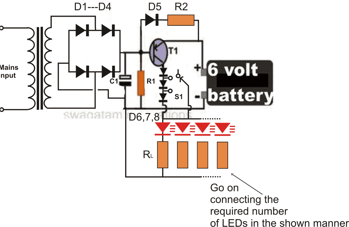
Parts List for the 150 LED emergency light circuit
R1 = 220 Ohms, 1/2 watt
R2 = 100Ohms, 2 watts,
RL = All 22 Ohms, 1/4 watt,
C1 = 100uF/25V,
D1,2,3,4,6,7,8 = 1N5408,
D5 = 1N4007
T1 = AD149, TIP127, TIP2955, TIP32 or similar,
Transformer = 0-6V, 500mA
3) Automatic Emergency Lamp Circuit with Low Battery Cut-off
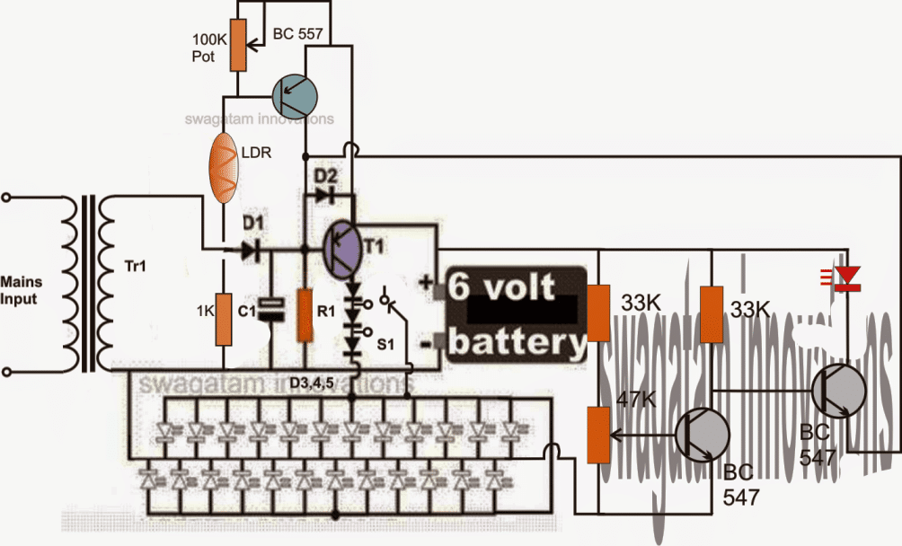
The following circuit shows how a low voltage cut off circuit can be included in the above design for preventing the battery from getting over discharged.
4) Power Supply Circuit with Emergency Light Application
The 4rth circuit shown below was requested by one of the readers, it is a power supply circuit which trickle charges a battery when AC mains is available, and also feeds the output with the required DC power via D1.
Now, the moment AC mains fails, the battery instantly backs up and the compensates the output failure with its power via D2.
When input Mains is present, the rectified DC passes through R1 and charges the battery with the desired output current, also, D1 transfers the transformer DC to the output for keeping the load switched on simultaneously.
D2 remains reverse biased and is not able to conduct because of higher positive potential produced at the cathode of D1.
However when mains AC fails, the cathode potential of D1 becomes lower and therefore D2 starts conducting and provides the battery DC back up instantly to the load without any interruptions.
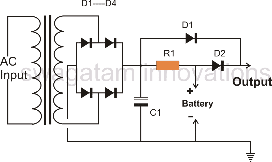
Parts List for an emergency light back up circuit
All Diodes = 1N5402 for battery up to 20 AH, 1N4007, two in parallel for 10-20 AH battery, and 1N4007 for below 10 AH.
R1 = Charging Volts - Battery volts / charging current
Transformer Current/Charging current = 1/10 * batt AH
C1 = 100uF/25
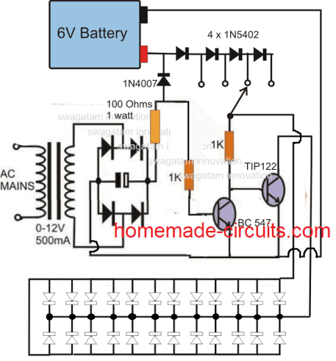
5) Using NPN transistors
The first circuit can be also built using NPN transistors, as shown here:
6) Emergency Lamp using Relay
This 6th simple LED relay changeover emergency light circuit using a battery back up which gets charged during mains presence and changes over to LED/battery mode as soon as mains fails. The idea was requested by one of the members of this blog.
Circuit Objectives and Requirements
The following discussion explains the application details for the proposed LED relay changeover emergency lamp circuit
I am trying to make very simple changeover circuit.. where I am using a 12-0-12 Transformer to charge a 12v Motorcycle battery via mains.
When the mains go off the battery will power a 10w LED. But, the problem is the relay is not switching off, when the mains goes down.
Any ideas. Want to keep it really simple.. 12VDC Relay / 2200uf-50v cap on Transformer.
My Response:
Hi, make sure that the relay coil is connected with the rectified DC from the 12-0-12 transformer. The relay contacts should be only wired with the battery and the LED.
Feedback:
Firstly Thanks for the Reply.
1. Yes the Relay Coil is connected with the Rectified DC.
2. If I connect the relay contacts to Battery / LED only, then how will the Battery get charged when Mains is ON?
If i am not missing anything..
The Design
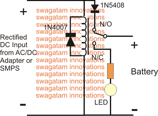
The above circuit is self explanatory and shows the configuration for implementing a simple LED relay changeover emergency lamp circuit.
Using a Relay and without Transformer
This is a new entry, and shows how a single relay can be used for making an emergency lamp with charger.
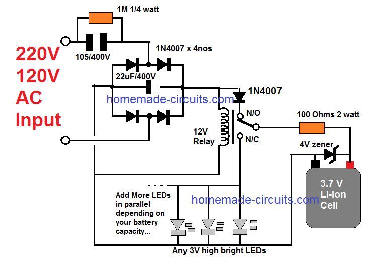
The relay can be any ordinary 400 ohm 12V relay.
While mains AC is available, the relay is energized using the rectified capacitive power supply, which connects the relay contacts with its N/O terminal. The battery now gets charged through this contact via the 100 ohm resistor. The 4V zener makes sure that the 3.7 Cell never reaches an over charged situation.
When mains AC fails, the relay deactivates, and its contact is pulled at its N/C terminals. The N/C terminals now connects the LEDs with the battery, illuminating it instantly via the 100 ohm resistor.
If you any specific questions, please ask using the comment box.
7) Simple Emergency Lamp Circuit using 1 Watt LEDs
Here I have explained a simple 1 watt led emergency lamp circuit using li-ion battery. The design was requested by one of the keen readers of this blog, Mr. Haroon Khurshid.
Technical Specifications
Can you help me design a circuit to charge a
nokia 3.7 volt battery by using regular nokia cellphone charger circuit and utilize that battery for lighting 1watt leds connected in parallel there should be light indicator and also automatic on of system in case of power failure kindly you consider my idea and design one
kind Regards,
Haroon khurshid
The Design
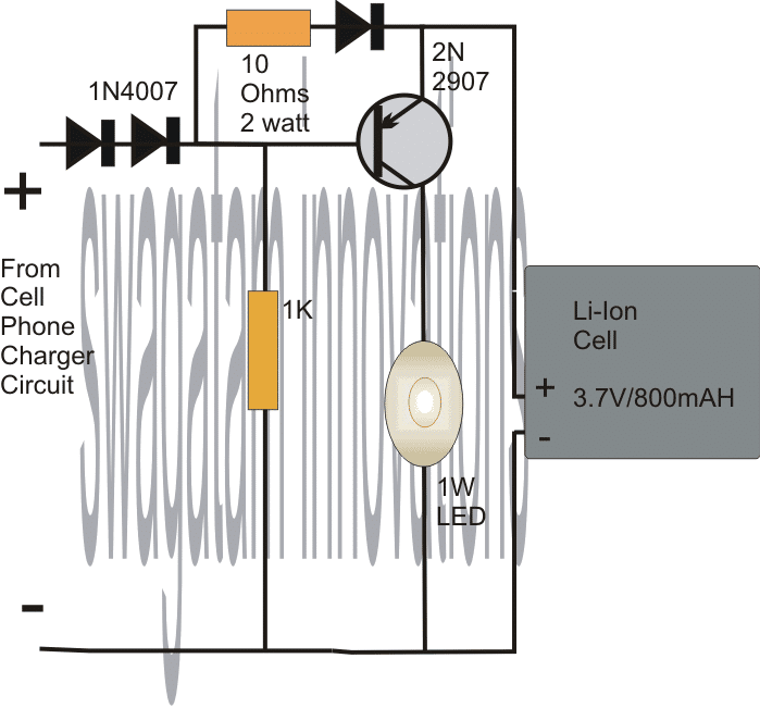
The requested 1 watt led emergency lamp circuit using li-ion battery may be easily built with the help of the below given schematic:
Adding a Current Control for the LED
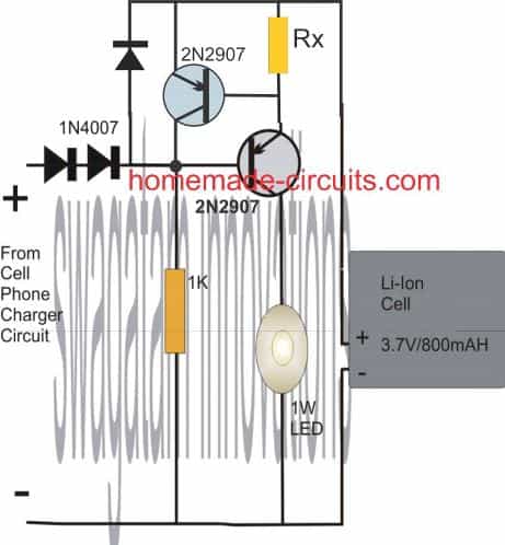
Rx = 0.7 / 0.3 = 2.3 ohm 1/4 watt
The voltage from the cell phone charger power supply is dropped to around 3.9V by adding diodes in the positive path of the supply. This should be confirmed with a DMM before connecting the cell.
The voltage should be limited to around 4V so that the cell is never allowed to cros the over charge limit.
Although the above voltage will not allow the cell to get charged fully and optimally, it will ensure the cell doesn't get damaged due to over charge.
The PNP transistor is held reversed biased as long as mains AC stays active, while the Li-Ion cell is charged gradually charged.
In case the mains AC fails, the transistor switches ON with the help of the 1K resistor and instantly illuminates the 1 watt LED connected across its collector and ground.
The above design can also be implemented using a transformerless power supply circuit. Let's the learn the complete design:
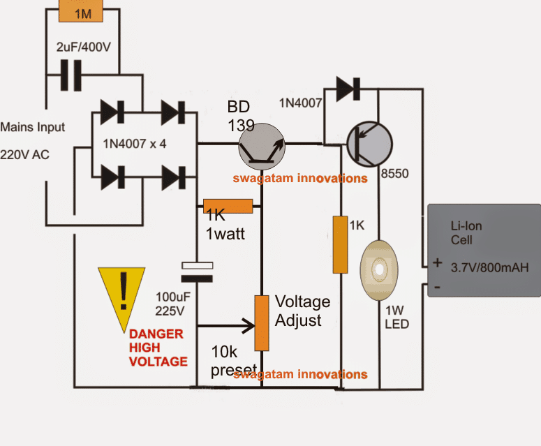
Before proceeding with the circuit details it should be noted that the following proposed design is not isolated from mains and therefore is extremely dangerous to touch, and it has not been verified practically. Build it only if you personally feel sure about the design.
Moving on, the given 1 watt LED emergency light circuit using Li-Ion cell looks quite a straightforward design. I have explained the functioning with the following points.
It's basically a regulated transformerless power supply circuit which can also be used as a 1 watt LED driver circuit.
The present design perhaps becomes very reliable owing to the fact that the dangers normally associated with transformerless power supplies are effectively tackled here.
The 2uF capacitor along with the 4 in4007 diodes form a standard mains operated capacitive power supply stage.
Adding an Emitter Follower for Voltage Regulation
The preceding stage which consists of an emitter follower stage and the associated passive parts form a standard variable zener diode.
The main function of this emitter follower network is to restrict the available voltage to precise levels set by the preset.
Here it should be set at around 4.5V, which becomes the charging voltage for the Li-ion cell. The final voltage that reaches the cell is around 3.9V due to the presence of the series diode 1N4007.
The transistor 8550 acts like a switch which activates only in the absence of power through the capacitive stage, meaning when AC mains is not present.
During the presence of mains power the transistor is held reverse biased due to the direct positive from the bridge network to the base of the transistor.
Since the charging voltage is restricted at 3.9V keeps the battery just under the full charge limit and therefore the danger of over charging it is never reached.
In the absence of mains power, the transistor conducts and connects the cell voltage with the attached 1 watt LED across the collector and ground of the transistor, the 1watt LED illuminates brightly....when mains power restores, the LED is switched OFF immediately.
If you have further doubts or queries regarding the above 1 watt led emergency lamp circuit using li-ion battery, feel free to post them through your comments.
8) Automatic 10 watt to 1000 watt LED Emergency Light Circuit
The following 8th concept explains a very simple yet an outstanding automatic 10 watt to 1000 watt emergency lamp circuit. The circuit also includes an automatic over voltage and low voltage battery shut off feature.
The entire circuit functioning may be understood with the following points:
Circuit Operation
Referring the below given circuit diagram, the transformer, bridge and the associated 100uF/25V capacitor forms a standard step down AC to DC power supply circuit.
The bottom SPDT relay is directly connected with the above power supply output such that it remains activated when mains is connected with the circuit.
In the above situation, the N/O contacts of the relay stay connected which keeps the LED shut OFF (since it's connected with the N/C of the relay).
This takes care of the LED switching, making sure than the LEDs are switched ON only in the absence of mains power.
However, the positive from the battery is not directly connected with the LED module, rather it comes via another relay N/O contacts (the upper relay).
This relay is integrated with a high/low voltage sensor circuit stationed for detecting the battery voltage conditions.
Supposing the battery is in a discharged condition, switching ON the mains keeps the relay deactivated so that the the rectified DC can reach the battery via the upper relay N/C contacts initiating the charging process of the connected battery.
When the battery voltages reaches the "full charge" potential, as per the setting of the 10 K preset, the relay trips and joins with the battery through its N/O contacts.
Now in the above situation if the mains fails, the LED module is able to get powered via the above relay and the lower relay N/O contacts and get illuminated.
Since relays are used, the power handling capacity becomes sufficiently high. The circuit is thus able to support in excess of 1000 watts of power (lamp), provided the relay contacts are appropriately rated for the preferred load.
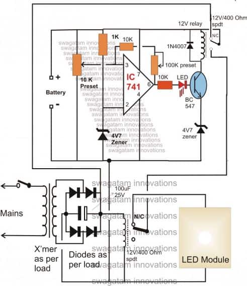
The finalized circuit with an added feature can be seen below:
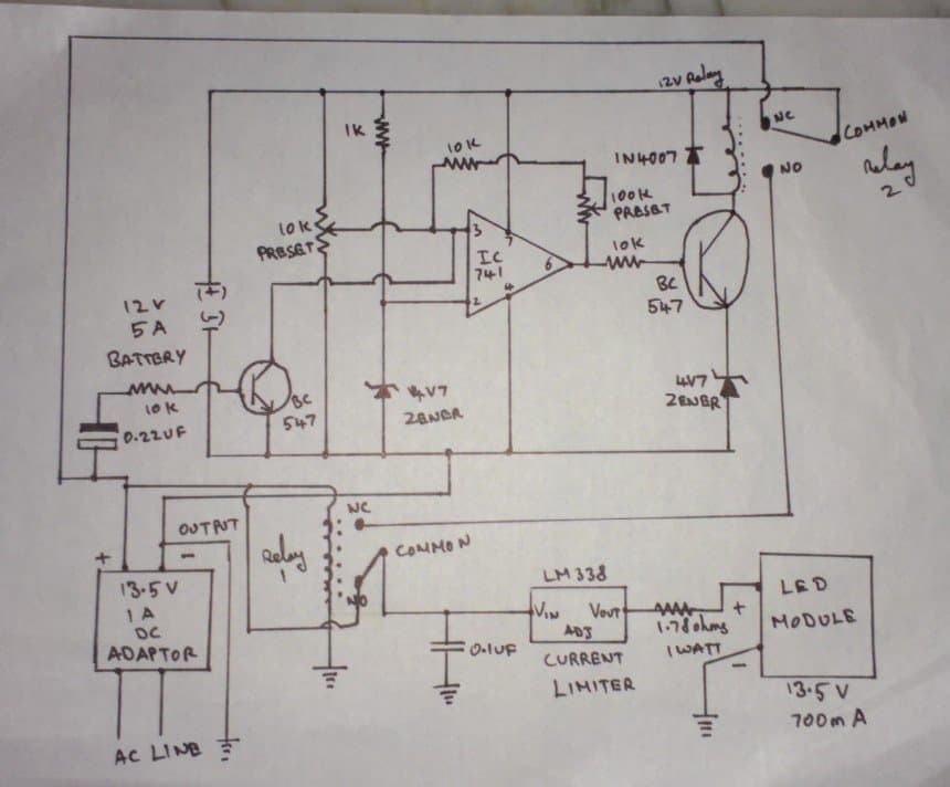
The circuit was drawn by Mr. Sriram kp, for details please go through the comment discussion between Mr Sriram and me.
9) Emergency Light Circuit Using a Flashlight Bulb
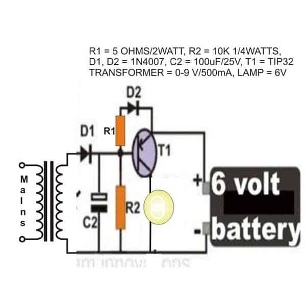
In this 9 idea I have explained the making of a simple emergency lamp using a 3V/6V flashlight bulb.
Though it's the world LEDs today, an ordinary flashlight bulb can also be considered a useful light emitting candidate especially because it's much to configure than an LED.
The shown circuit diagram is quite simple to understand, a PNP transistor is used as the primary switching device.
A straight forward power supply provides the power to the circuit when mains is available.
Circuit Operation
As long as power is present, the transistor T1 remains positively biased and therefore remains switched OFF.
This inhibits battery power from entering the bulb and keeps it switched OFF.
The mains power is also utilized for charging the involved battery via the diode D2 and the current limiting resistor R1.
However, the moment AC mains fails, T1 is instantly forward biased, it conducts and allows the battery power to pass through it, which ultimately turns ON the bulb and the emergency light.
The entire unit may be adjusted inside a standard AC/DC adapter box and plugged IN directly in to an existing socket.
The bulb should be kept protruding outside the box so that the illumination reaches the external surrounding amply.
Parts List
- R1 = 470 Ohms,
- R2 = 1K,
- C2 = 100uF/25V,
- Bulb = Small Flashlight Bulb,
- Battery = 6V, Rechargeable Type,
- Transformer = 0-9V, 500 mA
The Design and Schematic
10) 40 Watt LED Emergency Tubelight Circuit
The 10th awesome design talks about a simple yet effective 40 watt LED emergency tube light circuit which can be installed at home for acquiring uninterruptible illumination at the same time saving a lot of electricity and money.
Introduction
You might have read one of my earlier articles which explained a 40 watt LED street light system. The power saving concept is pretty much the same, through a PWM circuit, however the alignment of the LEDs has been laid in a completely different manner here.
As the name suggest the present idea is of an LED tube light and therefore the LEds have been configured in a straight horizontal pattern for better and efficient light distribution.
The circuit also features an optional emergency battery back up system which may be employed for getting an uninterruptible illumination from the LEDs even during the absence of normal mains AC.
Due to the PWM circuit the acquired backup can extend up to more than 25 hours on every single recharge of the battery (rated at 12V/25AH).
The PCB would be strictly needed for assembling the LEDs. The PCB must be an aluminum-back type. The track layout is shown in the below given picture.
As can be seen the LEDs are spaced at a distance of about 2.5 cm or 25mm from each other for enhancing maximum and optimal distribution of light.
Either the LEDs may be laid over a single row or over a couple of rows.
A single row pattern is shown in the below given layout, due to lack of space only two series/parallel connection has been accommodated, the pattern is continued further on the right side of the PCB so that all the 40 LEDs become included.
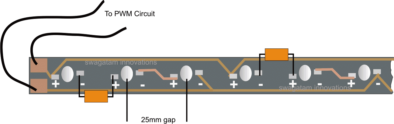
Normally the proposed 40 watt LED tube light circuit, or in other words the PWM circuit may be powered through any standard 12V/3amp SMPS unit for the sake of compactness and decent looks.
After assembling the above board, the output wires should be connected to the below shown PWM circuit, across the transistor collector and positive.
The supply voltage should be provided from any standard SMPS adapter as mentioned in the above section of the article.
The LED trip will instantly light up illuminating the premise with flood light brightness.
The illumination may be assumed to be equivalent to a 40 watt FTL with power consumption of less than 12 watts, that's a lot of power saved.
Emergency Battery Operation
If an emergency backup is preferred for the above circuit, it may be simply done by adding the following circuit.
Let's try to understand the design in more details:
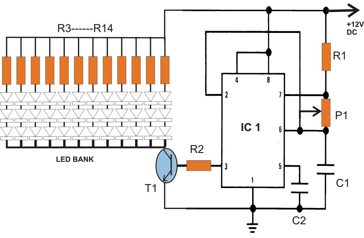
The circuit shown above is the PWM controlled 40 watt LED lamp circuit, the circuit has been elaborately explained in this 40 watt street light circuit article. You can refer it for knowing more about its circuit functioning.
Automatic Battery Charger Circuit
The next figure shown below is an automatic under voltage and over voltage battery charger circuit with automatic relay changeovers. The whole functioning may be understood with the following points:
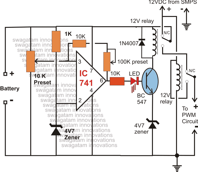
The IC 741 has been configured as a low/high battery voltage sensor and it activates the adjoining relay connected to the transistor BC547 appropriately.
Assume the mains to be present and the battery to be partially discharged. The voltage from the AC/DC SMPS reaches the battery through the N/C contacts of the upper relay which remains in an deactivated position because of the battery voltage which may be below the full charge threshold level, let's assume the full charge level to be 14.3V (set by the 10K preset).
Since the lower relay coil is connected to the SMPS voltage, stays activated such that the SMPS supply reaches the PWM 40 watt LED driver via the N/O contacts of the lower relay.
Thus the LEDs remains switched ON by using the DC from the mains operated SMPS adapter, also the battery continues to get charged as explained above.
Once the battery gets fully charged, the output of the IC741 goes high, activating the relay driver stage, the upper relay switches and instantly connects the battery with the N/C of the lower relay, positioning the battery in the standby condition.
However until AC mains is present, the lower relay is unable to deactivate and therefore the above voltage from the charged battery is not able to reach the LED board.
Now if suppose AC mains fails, the lower relay contact shifts to the N/C point, instantly connects the supply from the battery to the PWM LED circuit, illuminating the 40 watt LEDs brightly.
The LEDs consume battery power until either the battery falls below the low voltage threshold or mains power is restored.
The low battery threshold setting is done by adjusting the feedback preset 100K across the pin3 and pin6 of the IC741.
Over to You
So friends these were the 10 simple automatic emergency light circuits, for your building pleasure! If you any suggestions or improvements for the mentioned circuits please tell us using the comment box below.


Questions & Answers
Is S1 a automatic switch? If not then how it to be used manually? Thanks.
No, it's manual, initially it must be kept at the topmost point, then gradually brought to the lower points for optimizing the brightness as the LED gets dimmer.
sir i want to know that y u used a resister of 10k ohm in parallel in the 1st circuit
For providing the required negative base biasing so that it is able to conduct when mains supply fails.
The LED will be OK but will be dim due to low voltage, I am assuming it to be a white LED which needs 3V minimum for optimal glow.
use TIP127 for the transistor, use 10 ohm, 1 watt resistor for each LED (parallel connection)
remove all the diodes, they won't be required…..
…do not remove D1, D2, they are required.
Hi Swagatham,
I made this circuit.. Its working properly.. Thanks to you..
I wish to incorporate a Charging LED to the first circuit.. Please suggest a way..
Regards,
Ranju
Hi Ranju,
Connect low value resistor in series with D2 and connect an LED parallel to this resistor with its cathode towards the battery.
The resistor value may be calculated with the help of the following formula:
R = 3/I, where I is selected 1/10 of battery AH.
Thanks for the reply Swahatham..
It's perfectly done and working fine..
Please suggest a way to add an LED for full Charge indication for battery..
Good day Sir!
A question for the circuit: Using NPN transistor
1. Can I replace BC547 and TIP122 with a 2 TIP31C?
2. Can I omit the 4 DIODES but instead use a a SPST switch?
3. Can I use 1 watt LED accompanied by 100 ohms resistor instead of 24 5mm diodes?
Good day Achilles,
Although it doesn't look a good replacement but you may try it, might just work.
If you want to use a resistor in place of diodes, yes you can do it.
For 1 watt LED you will need to calculate the resistor value correctly as per the voltage specs.
good day sir!
a question for circuit using NPN transistor:
1. If I have 6V 4Ah battery how long will it take to charge?
2. I have a problem: my transformer generates a little heat, (but no so dangerous), after plugging the circuit for about 12 hours. Is that okay?
thanks a lot for the answer.
I need it ASAP. that is before my circuit fails… 🙂
I mean for the first group of question which is #3 is: not a diode a LED. thanks a lot again SIR!!!
with a 6v/500ma transformer, the battery should get charged within 8 hours of time.
you can use only two or three 1 watt leds not more than that.
use two in series without any resistor and no diodes at the transistor collector.
You can use two 1N4007 in parallel for each 1N5408, and TIP127 in place of BD140
Hey Sam,
I am a class 12th student, could I make this one easily for my board project and can you please tell me basically what are the steps that I should take to make this one?
I lvoe this project.
Hi Divyansh,
First procure all the components and also a general purpose PCB and then correctly assemble all the components over it very carefully by soldering them together using wire links.
Do all the connections correctly as per the given diagram.
can i use 12v battery here?
yes, but include 3 LEDs in each string
how many led in SERIES can I use? with 12v battery
how many hours will it take to charge the battery?
can you change the power supply of this emergency light with transformerless power supply? plssssss just requesting…i'll wait here…..
You can try this circuit:
https://www.homemade-circuits.com/2012/07/making-automatic-emergency-lamp-using.html
backup time will depend on battery AH and no of LEDs used.
Sir, What type capacitor is used PPC / others (C1 = 100uF/25V circuit for SATY for 150 LEDs)
in Power Supply Circuit with Emergency Backup
Is this correct?
1. I have 12v/7.5Ah battery that means my transformer should be .75 A and how many volts?
2.the Resistor is 12v(from battery) divided by .75 A(from transformer) =16 ohms right? or wrong?
3.diode should be 1n4007.
1) a 1amp trafo will also do, volts = 14V
2) resistor for what??
3)use 1N5402 not 1n4007
the resistor above is for what?
Hi Swagatam,
I want to thank you for the circuit which you have provided to me (3rd circuit) it is working fine.
This is saty here after long time, i thing u remember, according to the 3rd circuit for 150 LED with same setup i have built it.
1. want overload protect to the battery, since it is conneted to the mains always (470 ohms should be connected series to the D2, pls let me know is that right)
2. can i use 12v 7AH battery, if so please advice what are the components to changed or represent with clear diagram so that i can try to use the 12v battery with 3rd circuit so that i can have long backup hrs if absence of mains. Thanks in advance
Hi Saty,
The above circuits are not so advanced, and does not have proper protections, if you would like to have a perfect emergency light circuit then I would suggest you to make the following design:
https://www.homemade-circuits.com/2013/02/make-this-automatic-10-watt-to-1000.html
need ur help as fast u can…….totally confused for my project……which transistor is better a common base….aur ….common emitter……..
what is the equivalent for AD149 ( see circuit -150 LEDs requested by SATY).
TIP2955 can be used
just few minute ago, post some comment about protect batt from overdischarge. and now I can found preventing the battery from getting over discharged circuit here. sure I need modified for 3.7 Volt battery
it will be posted soon in the new article
BD140 not taking load of many leds. I had to remove it and made it manually by slide switch. I want to drive 48x 5mm led but it working with more then 12 led. What went wrong. I am using 500ma 9 v transformer and 6v 4 ah battery
use TIP127 in place BD140, it will surely work…..use a 50 ohm resistor with each LED and eliminate all the diodes at the collector of the transistor.
Interesting… How can i modify this circuit with trickle charging ( as shown in the Figure 5 ) using a 12 V 7Ah battery and all the LEDs replaced by two LED tubes ?? How can the switching diodes be placed as per your first design ???
thanks!, R1 may be increased to satisfy a trickle charge response.
You can connect more number of diodes in series with D2 for getting the required amount of voltage at the different junctions of the diode.
Sir I am planning to build a portable emergency light.
My intention is that to make the light from the emergency lamp available during power failure at night only…. So the following circuits suits best for me….
3.bp.blogspot.com/-moJh2ndZPhU/UoTi75WoLFI/AAAAAAAAFsY/k8xGQ713I8c/s1600/emergency+light+with+low+voltage+cut+off.png
Now can you help me in providing details with how to add a Higher voltage cut off for the battery so that during charging, when the battery tends to overcharge it should stop charging at a suitable voltage level..
I am also planning to place a transformerless power in place of the charging transformer to make the device very portable and can be hooked easily on the wall.. SO I AM USING A 3.35 uf capacitor in parallel with a 1 M,1/4W in the Phase line and then rectifying and bringing down the voltage to the charging voltage level using a suitable zener..
So i need your valuable suggestions on these..
i shall send a model diagram to your hitman inbox. Please check it out soon.
Arun, the linked circuit could be a bit complex to set up, moreover adding another high voltage cut off stage could make it even more confusing….it's better to go for the following design:
4.bp.blogspot.com/-3cQBlkTYxV4/URJZuN2F-3I/AAAAAAAAC_w/plOCVi6ZXzo/s1600/1+to+1000+watt+LED+emergency+light+circuit.png
the day/night feature is not there, but can be easily included.
Dear Swagatam,
my Class 9 son is eagerly ready to construct the 150 LED emergency circuit mentioned above. But I have not find AD149 transistor anywhere in Chandni market Kolkata. Can you kindly suggest something equivalent which is available nowadays in Kolkata ?
Regards
SUBHAGATA BANDYOPADHYAY
Dear Subhagata,
you can use TIP127 instead of AD149, or any other PNP equivalent will also do.
Regards.
Hi Swagatam, is it okay for me to use a 6v 1 amp transformer in the modified circuit? and is it okay for me to only use 10 LEDs? thanks
Hi John, yes you can use a 6V 1 amp transformer and also 10 LEDs, arranged as given in the above explained circuits.
i love these circuits but please can you post a simple 9v rechargeable battery circuit diagram for me, I need it for my project urgently pleeeeease. this is my mail address: ochar2men@gmail.com.
just connect the battery to a 12V/1amp DC source via a 220 ohm resistor, let it charge for 10 hours, you'll find it almost fully charged.
for indication you can connect an LED with a 1K series resistor parallel to the 220 ohm resistor, when this LED shuts off completely you can assume the batt to be fully charged.
Hi Swagatam…
How r u? First of all I Thank you for your great help and valuable suggestions.
I need help in my new project hope u dont mind. I have a old BPL Emergency lamp with dual Mercury tubes and now it's not in working condition. I just want to convert that unit into LED Emergency lamp. It has got 6V 4.5 Ah Battery. I would like to try the first circuit but with battery over charge protection. I also have a dual color(Red & Green) 3mm LED which I would like to use it as indicator for charging and Battery full.
Kindly let me know the modification to do in the Circuit.
Thank you in Anticipation and have great day
Vinay Rao
Thank you Vinay,
The above circuit cannot be used with an over charge cut off properly, you'll have to incorporate relays (5V) for your proposed requirement, as shown in the folowing link:
https://www.homemade-circuits.com/2013/02/make-this-automatic-10-watt-to-1000.html
the zener at the transistor emitter can be removed for a 6V battery.
For indications use LED from pin6 of the IC: one from positive to pin6 and another from pin6 to ground, both these LEds must be accompanied with individual 4k7 resistors.
Hello good people.
This blog gave me a lot of interesting information. Especially the power supply circuit with battery backup part.
The reason for this is that I am working on a Arduino based system for monitoring and controlling heating cables at my summer place. This system will eventually be gsm controlled so I quickly can get an update on for example the temperature in the bathroom. The part that I am stuck on is that I would like to have the Arduino to have a battery backup of some sort so it can still monitor the temperature around wunerable waterpipes, and possible notify me if mains power goes out. I'm thinking of using a car battery so it can last for ages if power goes out.
What changes will I have to make to the "Power Supply Circuit with Emergency Backup" circuit to make it work with a 12V car battery and still have it trickle charge slowly?
Thank you in advance for any advice.
Sincerely
– Fredrik
Thanks Fredrik,
You would require a just two diodes for implementing it.
I'll post the design in a new article and let you know soon.
Hi Swagatam,
I thank you for your guidance and support. I am sorry for not providing you the complete information about my requirement in my previous question. It was a mistake from my end. Well as I said I have an BPL Emergency light with dual small Mercury Tubes which is a Portable lamp with 6v 4.5ah battery. It has also got the 12v 500 ma separate adapter for charging purpose. This is being used only when there is a regular power cut in our place (Normally for 2 hrs daily). Hence we need to keep this plugged in to A/C mains. We used to charge it when the battery gets completely exhausted. We just switch it on manually when the power goes off (especially in the night).
Hence in the circuit suggested by you should be always connected to the Ac mains.
So kindly suggest a circuit with overcharge protection facility with an indication dual colored LED (Red n Green).
I would like to use the 1W power LED's (warm White) for this Lamp and I guess the maximum No of LED's I can use is 5 if I am not wrong for 6V 4.5 ah Battery.
Hope you understand my requirement. If u think I can use the same Schematic suggested by u for my previous blog by making some alteration then please suggest me the those alterations to be made. Hope u help me out in this matter.
Best regards
Vinay