In this post I have explained a sequentially advancing 25 LED timer circuit which may be initiated on the 1st day of December so that each LED lights up on each day until the 25th of December (on Christmas) when all the 25 LED can be seen lit up. The circuit was requested by Mr. Guy Mathews
Technical Specifications
I was tasked with a project from wife, and it has been so long since my college days where I played with circuits, plus they weren't one of my strong points in college, where I'm not sure where to start.
My challenge is my wife is putting together a Christmas gift for my niece and she purchased 25 strands of LED battery operated LED lights.
The object is to have one strand of LED lights to come on every day. So on Dec 1, the timer can be turned on, and almost immediately the first strand will light, and then the second day the another strand will come on.
My struggles, other than how to actually design the circuit, are will the batteries last 25 days if the lights run 24 hours a day, would I be able to design the circuit where once on the lights don't turn off, and if designed this way will the batteries die before 25 days is up.
Could the circuit be designed with a bypass where if batteries needed to be replaced, the circuit could be corrected to get back to the correct amount of lights (or the day) where it stopped? Any help, advice, suggestions on where to look would be greatly appreciated. Best Regards,
Guy Mathews
The Design
The proposed digital Christmas candle light timer circuit can be implemented by configuring the above two circuits with the help of the following instructions:
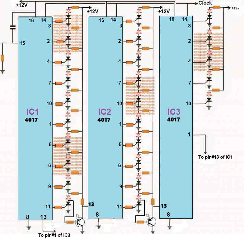
The left diagram above forms the 25 LED timer circuit which is supposed to light up in sequence from day#1 when the circuit is switched ON, until the 25he of December when the final 25th LeD lights up, at the rate of 1 LED per day.
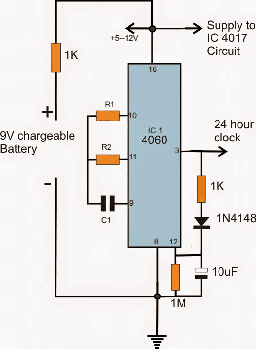
The stage is formed by wiring or cascading three IC 4017 ICs. The clock inputs of all the three ICs are rigged with the clock output of the right hand side circuit using IC 4060, whose pin3 output is to be connected with the pin14 of all the IC 4017.
R1, R2 and C1 of IC1 are calculated such that pin3 produces a high clock after a period of exactly 24 hours, once the system is switched ON.
This 24 hour clock pulse is fed to the pin14 of the three 4017 ICs so that a high logic shifts in sequence from pin3 of IC1 each day until the 25th day when the last LED at pin#1 of IC3 lights up.
The circuit is powered using two 9V rechargeable batteries, one being connected directly with the supply pins of the IC stages while the other connected through a 1K resistor.
The battery which is connected through a 1K resistor is permanently connected with the circuit and makes sure that the ICs are always powered with the minimum required current, in order to sustain the memory of the ICs in case the main battery gets exhausted in the course of the 25 day period and while the user removes it for recharging and replacing it back.
Parts List for the First Circuit
- IC1-----IC3 = 4017
- T1, T2 = BC557
- pin15 capacitor, resistor are 0.22uF and 1M respectively
- rest of the resistors are all 4k7
- SCRs are C106
- All LEDs are amber LEDs, 20 mA 5 mm

Questions & Answers
Hi Swagatam,
I have tried your suggestion and it probably resets the CD4017 but the BT169’s will not turn off until power is removed. I had to skip pins 3 and 2 of the second cd4017 and used pin 4 and pin 7 to get the 11th and 12th led to light correctly. Works great as far as lighting the LEDs with each clock. I tried using pin 10 of the second CD4017 to reset both CD4017s individually and together. Didn’t work because power was not interrupted to the BT169s. I tried using a TIP32 to power the circuit and switching it off with pin 10 of the second CD4017. I tried a number of different resistor combinations. I can get the circuit to light correctly and turn off and restart, but there are some inconsistencies. Used 470R to the base of TIP32 from pin 10 and about 230R (2-470rs in parallel) to the positive rail.. I changed all the LEDs to blue because red and green would not turn off. Pin 11 of the first CD4017 flashes off but stays on after the first cycle. All the LEDs light and turn off as required for the first cycle. Then on the second cycle pins 4 and 7 of the second CD4017 light with pins 9 and 10 of the first CD4017 and the pin 11 of the first CD4017 stays lit. So I have created a bastard circuit. Help!!!!
Hi Norman, the TIP32 method should have worked. Please check the following concept which uses the same idea for resetting the SCRs.
https://www.homemade-circuits.com/sequential-bar-graph-turn-light/
Hi Swagatam,
Thanks!
Yes, the changes to the diagram work perfectly. What changes would be made to get the circuit to repeat over and over? So in my case I have 12 LEDs. After the 12th LED lights, I would like the next clock to reset the circuit. How would I do that?
Hi Norman, please connect the pin which is next to the last LED pin with pin 15 of the Ic, and make sure the pin15 is also connected to ground via a 10k resistor.
Hi Swagatam,
I came across this circuit and would like to use it to light 12 LEDs. Start with one LED and add another LED with each clock signal. I would like the circuit to repeat the cycle over and over. Light 1 Led, light 2 LEDs, Light 3 LEDs, light 4 LEDs……….Light 12 LEDs and then start over with 1 LED, light 2 LEDs, …..etc. The circuit looks incomplete as there is no connection to voltage for the LEDs. I bread boarded it with voltage connected to the LEDs and it works. I am using two CD4017’s for the 12 outputs. I eliminated the BT169 and LED from pin 11 of the first CD4017 because it would not light as pin 11 supplies a signal to activate the transistor to ground pin 13 of the second CD4017. I skipped pin 3 on the second CD4017 and used pin 2 and pin 4 and pin 7 because pin 3 stayed lit whenever power was applied. I also put a LED indicator on the transistor that grounds pin 13 of the second CD4017 and it flashes when pin 11 sends its signal. The second CD4017 steps through pin 2, pin 4, but not pin 7 until pin 11 sends another signal. I connected pin 10 back to pin 13 of the first CD4017. The indicator LED on the transistor flashes with each 11th clock signal, so I guess that is what it is supposed to do. One problem is the second CD4017 can only step while pin 13 is grounded by the transistor which lasts for only two steps. I am using 5v, so my resistors are 100R where your circuit uses 12v(according to the diagram) and 9v for the clock according to the write up. If you can take a look at this, much appreciated.
Thank you Norman,yes there were a few mistakes in the circuit, I have corrected them now, please check out the new updated diagram, and let me know if you have any further doubts.
Let me know what you find out and thanks for taking the time to help me.
Actually I talked with Mr. GR, and this is what he said:
“Hi sir,
With the Arduino version 1.6.7 I was able to make single channel but not dual or above, but with the latest update 1.8.4 I have to test that, only then I can confirm.
Once the current assignments are done, I will try proceding with this project.
Regards”
Will keep you updated with the latest.
Is there a decent dual channel oscilloscope DIY kit out there that is not cost prohibitive? I really need a scope. I want to build it myself and it would be nice if it were dual channel and digital.
Any suggestions?
Don
Hi there, presently I do not have it in my website, however I will inquire this with Mr. GR who is an Arduino expert, may be he will be able to design one for you using Arduino…..kindly be in touch.
Hi, I've been watching your blog and it's amazing. I need help with a project, I need to make a leds sequence (40 leds) that make at least 3 effects, using any IC except pic or arduino. I've been searching and trying, but I´m just able to make one sequence(cascade). It would be great if you could help me. Thanks and keep going with this blog, nice job.
Hi, I am glad you liked my blog….can you please specify the supply voltage preferred for your circuit and the LED current specification…I'll try to design it for you.
Dear swagatam I need your help regarding my luminous inverter in that used MOSFET p80nf55eg with ic mcz33883 its working good last four years but last week it is not working on backup mode mains charging working, I have checked three caps 4700 MFD 25 volt leaki replaced and 33883 ic detect faulty its also replaced it is ON for seconds only and its overload led glow with beep. I replaced its all MOSFET status is same after that one more thing the output transformer at the time of switching giving very big sound. I try to
connect with it 7 ah battery its worked with low voltage led glow for 1 minute. Pls advise what is the problem in that.
Dear AK, it won't be feasible for me to judge the fault without practically checking the issue…you may have to contact the dealer technician to troubleshoot the problem.