• Skip to main content
  • Skip to primary sidebar

Homemade Circuit Projects

Need circuit help? Post them in the comments! I've answered over 50,000!

Blog | Categories | About | Hire Me | Contact | Calculators-online
You are here: Home / Automobile Electronics / How to Make Car LED Bulb Circuit

How to Make Car LED Bulb Circuit

Last Updated on June 1, 2026 by Swagatam 8 Comments

Typically all car turn signal lamps are around 12 to 20 watt rated which are traditionally incandescent bulb types and produce much lower light intensities compared to LED lights. Here I have explained how these lamps can be replaced with high efficiency, high intensity car LED bulbs.

Table of Contents
  • LED Car Bulb Design
    • Technical Specifications of the 3020 LEDs are:
  • Construction
    • Circuit Diagram

LED Car Bulb Design

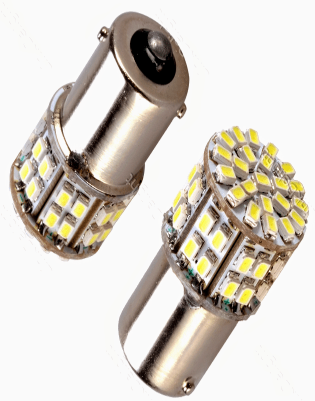
The image below shows what could be a car LED lamp directly replaceable over the existing holder.

It shows a decent looking arrangement of flat, tiny SMD LEds in a circular pattern for enabling optimal distribution of light via the enclosed hind reflector.

The LED used here are the 3020 SMD LEDs, these tiny light emitting diodes are identical to the ordinary 5mm LEDs with their specs, however if we compare their light intensities, the witnessed difference appears to be huge, where the 3020 easily wins by an outstanding margin, that's why these LEDs are much preferred in place of the ordinary 5mm LEds nowadays.

Technical Specifications of the 3020 LEDs are:

  • Forward voltage: 3 to 3.2V
  • Forward current: 30mA optimal
  • Luminous Efficiency: 100-110lm/w
  • Size: 3.0x2.0x1.3mm
  • Lifetime: 50,000hrs
Making car LED bulb circuit using SMD LEDs

Construction

In the above image, we can see the LEDs assembled over pcs of PCB strips, tiled in a particular calculated manner.

The vertical PCBs are 7 in numbers, and have 4 LEDs on each strips.

One circular PCB consisting of 22 LEDs can be seen positioned over the vertical PCB structure.

The vertical PCBs thus include 7 x 4 = 28 nos of 3020 LEDs, while the circular PCB mount 22 nos of LEds, giving a total of 28 + 22 = 50 LEDs

These 50 LEDs are connected to form 12 strings of 4 LEDs each, and a single string of 2 LEds.

Each of the 12 strings must have their own individual series resistor (SMD) whose value could be around 55 ohms 1/4 watt.

The single 2 LED string must associate a separate 250 ohm, 1/4 watt resistor.

These resistors act like current limiters for safeguarding the LEds from car alternator voltage fluctuations and also help to keep the illumination level across all the LED groups as uniform as possible.

The resistors can be installed at the rear side of the PCB strips.

The circuit diagram for the proposed simple car LED lamp is shown below:

Circuit Diagram
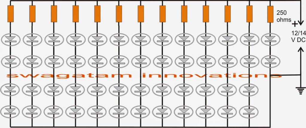
simple car LED bulb circuit using 3020 SMD LEDs

You'll also like:

  • 100led 2How to Illuminate 100 LEDs from 6 Volt Battery
  • Arduino Random RGB Light Generator Circuit
  • car radiator indicator circuit 1Car Radiator Hot Indicator Circuit
  • CREE XM-L T6 LED Driver Circuit – Specifications and Practical Application

Filed Under: Automobile Electronics, Lamps and Lights Tagged With: Bulb, LED

About Swagatam

I am an electronics engineer and doing practical hands-on work from more than 15 years now. Building real circuits, testing them and also making PCB layouts by myself. I really love doing all these things like inventing something new, designing electronics and also helping other people like hobby guys who want to make their own cool circuits at home.

And that is the main reason why I started this website homemade-circuits.com, to share different types of circuit ideas..

If you are having any kind of doubt or question related to circuits then just write down your question in the comment box below, I am like always checking, so I guarantee I will reply you for sure!


Previous Post: « Simple Automatic Plant Watering Circuit for Monitoring Soil Moisture
Next Post: Make this Red LED Sign Circuit »

Reader Interactions

Questions & Answers

Total Posts: 8
Newest Oldest
Safak TASKIN
July 5, 2024 • 2 years ago #153563

Hello. When operating voltage is applied to LEDs, they tend to draw insatiable current. (Avalanche current) To limit this and provide the desired operating voltage, series resistors are connected.

Reply
Abdul Basit Momin
October 22, 2019 • 7 years ago #71249

How can we make 50 led string in series of this bulbs

Reply
SwagatamAdmin
October 22, 2019 • 7 years ago #71264

Make 16 strings having 3 series LEDs with a calculated resistor. Then connect all the strings in parallel with 12V supply

Reply
Abdul Basit Momin
October 23, 2019 • 7 years ago #71307

And how will the circuit for 230v

Reply
SwagatamAdmin
October 23, 2019 • 7 years ago #71316

for 230V connect all of them in series and use the first circuit from this article to control it

https://www.homemade-circuits.com/how-to-make-led-bulb-circuit/

Reply
satheesh k Nalluswamy
May 3, 2016 • 10 years ago #40679

Thanks for your help

Reply
satheesh k Nalluswamy
May 2, 2016 • 10 years ago #40663

Dear sir,
please provide above the led resister calculation

Reply
SwagatamAdmin
May 3, 2016 • 10 years ago #40674

Dear Satheesh, you can use the following calculator for knowing the results:

https://www.homemade-circuits.com/p/led-resistor-calculator_21.html

Reply

Need Help? Please Leave a Comment! We value your input—Kindly keep it relevant to the above topic! Cancel reply

Your email address will not be published. Required fields are marked *

Primary Sidebar


Categories

  • Arduino Projects (95)
  • Audio and Amplifier Projects (134)
  • Automation Projects (18)
  • Automobile Electronics (103)
  • Battery Charger Circuits (89)
  • Datasheets and Components (109)
  • Electronics Theory (150)
  • Energy from Magnets and Earth (40)
  • Games and Sports Projects (11)
  • Grid and 3-Phase (20)
  • Health related Projects (27)
  • Home Electrical Circuits (13)
  • Indicator Circuits (16)
  • Inverter Circuits (100)
  • Lamps and Lights (163)
  • Meters and Testers (72)
  • Mini Projects (28)
  • Motor Controller (68)
  • Oscillator Circuits (30)
  • Pets and Pests (15)
  • Power Supply Circuits (91)
  • Remote Control Circuits (50)
  • Security and Alarm (65)
  • Sensors and Detectors (107)
  • SMPS and Converters (46)
  • Solar Controller Circuits (62)
  • Temperature Controllers (44)
  • Timer and Delay Relay (50)
  • Voltage Control and Protection (44)
  • Water Controller (37)
  • Wireless Circuits (31)


Circuit Simulator

circuit simulator image


Subscribe to get New Circuits in your Email


Other Links

  • Privacy Policy
  • Cookie Policy
  • Disclaimer
  • Copyright
  • Videos
  • Sitemap

People also Search

555 Circuits | 741 Circuits | LM324 Circuits | LM338 Circuits | 4017 Circuits | Ultrasonic Projects | SMPS Projects | Christmas Projects | MOSFETs | Radio Circuits | Laser Circuits | PIR Projects |


Recent Comments

  • Swagatam on 2 Cool 50 Watt Inverter Circuits for Students and Hobbyists
  • way on 2 Cool 50 Watt Inverter Circuits for Students and Hobbyists
  • Swagatam on 2 Cool 50 Watt Inverter Circuits for Students and Hobbyists
  • Swagatam on The Perfect FM Radio Circuit using TDA7000 IC
  • Swagatam on 9 Simple Sine Wave Generator Circuits Explored

Social Profiles

  • Twitter
  • YouTube
  • Instagram
  • Pinterest
  • My Facebook-Page
  • Stack Exchange
  • Linkedin

© 2026 · Swagatam Innovations