If you feel strobe lights very interesting but are disappointed by the fact that these wonderful light effects can be produced only through complex xenon tube then probably you are quite mistaken.
It is very much possible to make any light a strobe light if you are equipped with a proper driving circuit capable of handling different lighting devices to generate the desired strobe light effect.
The present article shows how a circuit as basic as a multivibrator may be modified in different ways and made compatible with ordinary bulbs, lasers, LEDs to produce spectacular light pulses.
A strobe light may be used for warning, scientific analysis or as an entertainment device, whatever may be the application the effects are simply dazzling. In fact it is possible to make any light a strobe light through a proper driving circuit. Explained with Circuit Diagrams.
Difference Between Flashing and Strobing
A light when made to blink or flash indeed looks pretty eye-catching and that’s the reason why they are used in number of places as a warning device or for decorations.
However a strobe light in particular may also be considered a flashing light yet is uniquely different from ordinary light flashers. Unlike them in a strobe light the ON/OFF pattern is so optimized that it produces sharp dazzling pulsed flashes of light.
There’s no doubt why they are mostly used in conjunction with fast music to enhance a party mood.
Nowadays green lasers are being popularly used as a strobing device in party halls and gatherings and have become hot favorite among the new generation.
Whether it’s LEDs, lasers or an ordinary filament bulb, all can be made to flash or rather strobe using an electronic circuit capable of producing the required pulsed switching in the connected lighting element.
Here we will see how we can make any light a strobe light using a simple electronic circuit.
The following section will acquaint you with the circuit details. Let’s go through it.
Pulsating any Light to Produce Strobing Effect
Through one of my previous articles we came across a nice little circuit able to produce interesting strobe effects over a few of the connected LEDs.
But this circuit is only suitable for driving low power LEDs and thus cannot be applied to illuminate big areas and premises.
The proposed circuit allows you to drive not only LEDs but also powerful lighting agents like incandescent bulbs, lasers, CFLs etc.
The first diagram shows the most basic form of a multivibrator circuit using transistors as the main active components. The connected LEDs can be made to strobe by suitably adjusting the two potentiometers VR1 and VR2.
UPDATE:
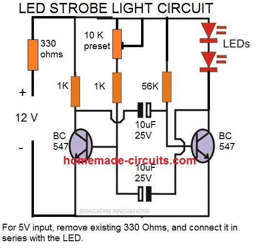
I have explained a few transistorized strobe light circuits in this article, however the below shown design is the easiest one and is tested by me. So you can begin with this design, and customize it as per your own preference and liking.
Video Illustration
The above discussed simple design can be further modified as I have explained below for greater control and refined outputs.
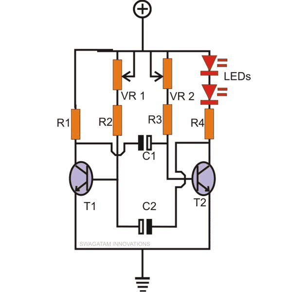
The above circuit forms the base for all the following circuits through some suitable modifications and additions.
Using a Flashlight Lamp as Strobe Light
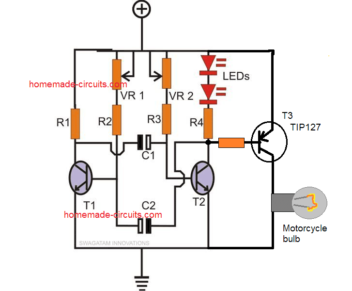
For example if you want to illuminate and pulsate a small torch bulb using it, you would just need to do the simple modifications as shown in the second diagram.
Here by adding a PNP power transistor and triggering it through the collector of T2, a torch bulb is easily made to strobe. Off course, optimum effect is achieved only through proper adjustment of the two Pots.
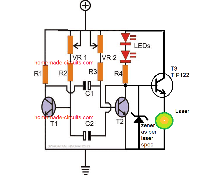
As already discussed already in the previous section, green laser pointers are pretty popular nowadays; the diagram illustrated shows a simple method of converting the above circuit into a pulsating green laser pointer strobe light.
Here the zener diode along with the transistor works like a constant voltage circuit ensuring that the laser pointer is never supplied with a voltage higher than its maximum rating.
This also ensures that the current to the laser can also never exceed the rated value.
This the zener and the transistor functions like a constant voltage and also an indirect constant current driver for the laser.
Using AC 220V or 120V Lamp as Strobe Light
The next diagram shows how an AC mains lamp may be used as a strobing light source using the above circuit. Here a triac forms the main switching component receiving the required gate pulses from T2’s collector.
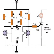
Thus we see that through the above circuit designs it becomes very easy to make any light a strobe light simply by doing the relevant modifications within a simple transistor based circuit as exlained in the above examples.
Parts List
- R1, R4, R5 = 680 Ohms,
- R2, R3 = 10K
- VR1, VR2 = 100K pot
- T1, T2 = BC547,
- T3, T4 = BC557
- C1, C2 = 10uF/25V
- Triac = BT136
- LEDs = as per choice
Police Strobe Light Circuit
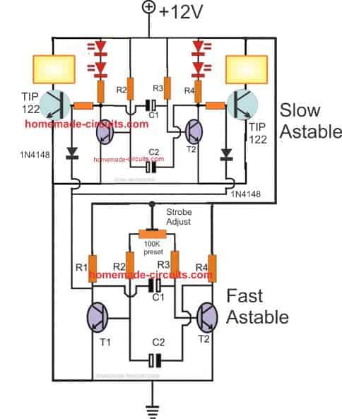
For the slow astable use the following parts:
- R1, R4 = 680 Ω
- R2, R3 = 18K
- C1 = 100 μF
- C2 = 100 μF
- T1, T2 = BC547
For the Fast astable use the following parts
- R1, R4 = 680 Ω
- R2, R3 = 10K
- preset = 100K
- C1 = 47 μF
- C2 = 47 μF
- T1, T2 = BC547
36 Watt Current Controlled Strobe LED Light
This 36 watt LED strobe light circuit with current control feature was requested by one of the dedicated readers of the website, Mr. Rohit.
The design idea can be learned from the following explnation:
I am trying to make a fast flash LED strobe light like the ones used by cameramen for photography. I have seen some circuits on your website regarding LEDs like constant current driver, powering high wattage LED lights, LED strobe light. However, I think my application is a combination of these projects.
So what I want to do is power 18W or 36W LEDs for 1 microsecond flash and need a constant current driver so that every flash has the same intensity.
I hope to hear from you soon. Feel free to contact me if you have any questions by email or call me to discuss further
The complete circuit diagram for the 36 watt high power LED strobe light with current control feature can be witnessed in the following image:
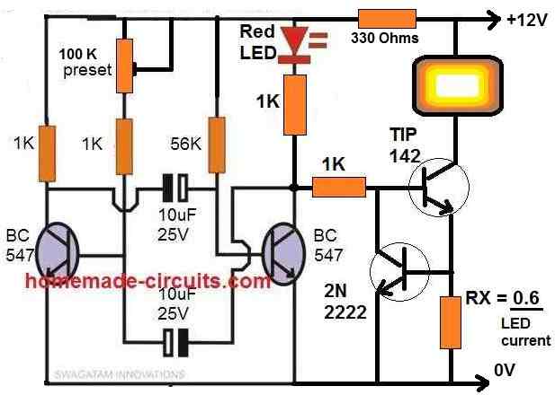
Parts list
- All resistors are 1/4 watt 5% unless specified
- 1K = 4nos
- 330 ohms = 1no
- 56K = 1no
- 100k preset = 1no
- RX = as given in the diagram
- Capacitors
- 10uF/25V Electrolytic = 2nos
- Transistors
- BC547 = 2nos
- TIP142 = 1no
- 2N2222 = 1no
- RED LED = 5mm 20mA type
- PowerLED = 12V, below 5 amps.


Questions & Answers
Hy Swagatam
For a zeotrope project with an arduino Uno, I want to make a strobe with power LEDs. I need to simultaneously flash 5 LED matrices of 50 watts of 1.5A each operating at 36 volts. In total it will be 250 watts. I will use a 36V DC 4A power supply. This power supply is not a constant current LED driver. My LEDs must flash at a frequency of 10 to 30 times per second and the adjustable pulse duration will be from 1ms to 10ms. I am thinking of a circuit that will charge power capacitors and discharge into the LEDs. The LED matrices will be in parallel, driven by one or more mofsets. I am an electronics amateur, I do not have the knowledge to create an electronic circuit and find the right value of the components. Can you help me produce a clear electrical diagram as well as the value of the components?
I realize this is a lot of work. Thanks for pointing me in the right direction.
The following points should be considered:
1. Limit the peak current to avoid damaging the LEDs. The duration of the light pulse will also be determined by the capacitor discharge rate and the resistance in the circuit. Perhaps add limiting resistors in series with each group of LEDs and use inductors to limit the current rate of change (dI/dt)?
2. Discharge voltage: The voltage across the capacitors will decrease during discharge. Ensure that the voltage remains within the LED operating range (30 to 38V) for the duration of the pulse for optimal illumination.
3. Capacitor charging time: To achieve the desired flash rates (10 to 30 Hz), the capacitors must recharge sufficiently quickly between each discharge.
4. Flash capacitors: One or more high-capacitance capacitors (the exact value will depend on the desired pulse duration and the required current). The capacitors’ nominal voltage will also need to be considered.
Also, add smaller decoupling capacitors for fast transitions.
5. Power transistors to switch the capacitor discharge across each LED array. These will be controlled by the Arduino. Perhaps one or more IRLZ44Ns.
6. Flyback diodes: Diodes placed in reverse parallel with the LED arrays to protect the transistors from overvoltage when the power is turned off.
7. Safety discharge resistors for the capacitors when the system shuts down.
Hello Fabrice, Can you please tell me which capacitor are you referring to that needs to be charged and discharged, and what is the purpose of these capacitors? Capacitors are normally used in oscillator circuits for enabling the switching frequency at their outputs, or for causing delay in the ON/OFF periods of the load. However if an Arduino is used then these capacitors may not be required, according to me. Limiting the current to the LEDs is not a problem…
Swagatam,
Thanks for the quick response!
I want to use the principle of a photographer’s electronic flash.
I don’t know if I’m wrong, but the idea of using power capacitors is to allow me to use a smaller power supply. My five 50W LED arrays would require a 10A constant current power supply at 36V. These power supplies are rare, big and expensive! If my circuit is well optimized, a 36V power supply at 3A should allow four power capacitors to be charged during the period when the LEDs are off.
Four power capacitors in parallel would each have a value of about 1200uF/60V for a total of 4600uF. I don’t know if it would work. I haven’t tested it on the breadboard yet, as I don’t have the right components on hand.
Also, my electronics skills are very limited.
What do you think of my approach?
Thank you Fabrice, Now I have understood the application fully, and it can be designed using both an Arduino, or without an Arduino, through discrete components… please let me know which method do you prefer?
Great! I can’t wait to see what it would look like with an Arduino. Thanks for your time!
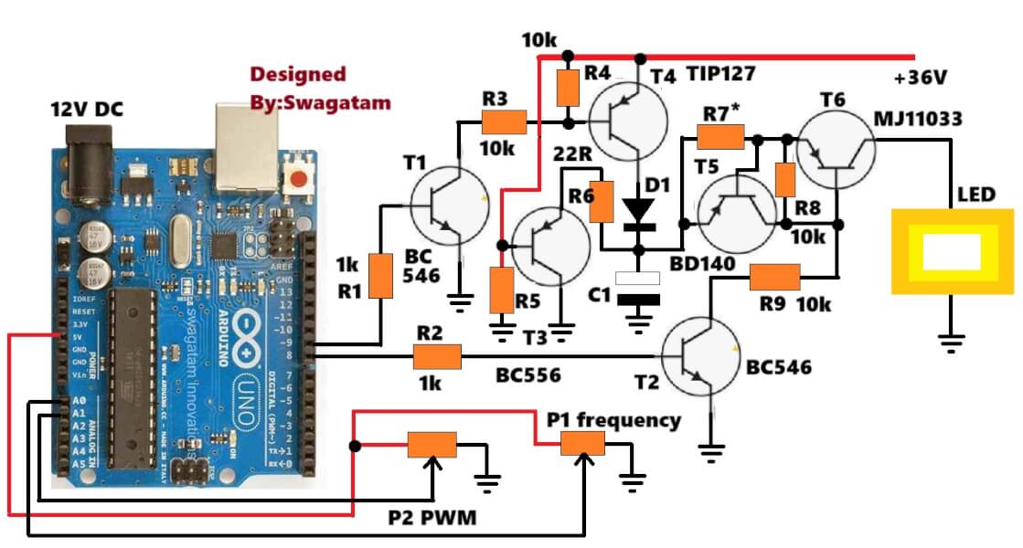
Sure!! here’s the code and the diagram:
https://www.homemade-circuits.com/wp-content/uploads/2025/05/Arduino-code.txt
Thanks, Swagatam, I like your suggestion. It doesn’t use MOSFETs. It’s very informative. I’ll test it on a breadboard as soon as I have all the components. The MJ11033 power transistor is expensive. It’s a 50A, 120V Darlington. Can I replace it with another one, and what is the acceptable value range? I have other questions:
1) Can you also give me the values of R5, R6, and R7?
2) What is the role and value of C1? Is it a single capacitor or several power capacitors capable of supplying the necessary power for my five 50W LED arrays?
3) What is the value of D1?
4) Will this setup work with a 36V, 3A power supply?
5) Do my LED arrays need a current-limiting resistor, or does this setup deliver a constant current of 1.5A?
6) Do the LED arrays require a freewheeling diode?
Thank you for your patience and for sharing your knowledge!
No problem Fabrice, hope it works as expected! You can check the response correctly by initially keeping the switching frequency slower, maybe around 2 seconds ON/OFF which will clearly give you an idea how the charging discharging process is happening…
You can also use a MOSFET like IRF9540 in place of T6 for improved conduction. Or you can replace the MJ1033 with a TIP127 and check if it works without heating up or not, or attach a large heatsink to it.
R5 caan be 10k, R6 is 22 ohms, and R7 = 0.6/Max LED Current
C1 is your charge/discharge capacitor, it will depend on your circuit specifications. It should be ideally many capacitors in parallel.
D1 can be a 6A4 diode.
Yes, the output circuit is designed to work with 36V, but make sure to supply a 12V to the Arduino black DC socket.
Since the current is limited by T5, T6, R7, no resistor is required for the LEDs, but for better safety you can put a 2 ohm 2 watt resistor in series with the LEDs.
The pots can be 100k each.
Freewheeling diode is not required because there’s no inductor or capacitor involved across the LED.
Thanks, Swagatam! This is getting very interesting. I can’t wait to try it out.
I understand this setup runs on 36V. I was initially aiming for a 3A power supply. How do I know if that will be enough?
Thanks for your advice. I’ll continue to follow your other projects on your blog.
Thank you Fabrice, you are most welcome!
Swagatam,
I think I expressed myself poorly. In my case, the load will consist of 5 LED arrays in parallel. Each array has a nominal current of 1.5A. The total load will therefore be 7.5A. The goal of this project is to supply 7.5A for a single pulse with a power supply of only 3A. Can the circuit you’re proposing do that? Regarding R7 = 0.6/Max LED Current, is the formula: 0.6 divided by 7.5A (Max LED Current)?
Thank you Fabrice, For 5 LED arrays you may have to use the specified MJ11033 transistor for T6 or a MOSFET.
Unfortunately a 36V 3amp can never be converted to 36V 7.5 amps. I checked your initial comment but could not find this specification in it, otherwise I would have informed you about this before.
Yes, please use 7.5A in the formula, and the wattage of the resistor will be 7.5 * 0.6
For better safety you may have to put series resistor 1 ohm 3 watt with each LED array.
No problem Fabrice, let us know how it goes.
The input current does not matter as long as the load voltage is also rated same as the input supply. However, even if the load voltage spec is lower than the input supply still it won’t matter because we have a current limiter stage at the output. For optimal performance and efficiency, the load voltage should be same as the input supply voltage and current rating lower than the input current rating.
If staring with 12 volt led strove light, how do I modify it to be constantly on ( no strove or flash)?
To make the LEDs ON constantly you can add a switch across the collector/emitter of the transistor which is driving the LEDs. This switch can be used to bypass the transistor switching and allow the LED to light up directly without strobing.
Hi Swagatam
Spoke to you few months ago.
Now I copy a circuit for a strobe LED and works fine with 13.5V except this circuit does NOT work with less voltage, say with 3V or 4V or 5V. It does not work not even with 10V or 11Volts
I use for this 13.5 V circuit a 3.3KΩ resistor, a BC547 transistor, a 150Ω Resistor and two caps. One is 330μF and the second is 100μF on a bread board
What component should I need to remove or replace or add in order this LED to work as strobe like it does now but with 13.5 Volts only
I thank you in advance for your reply
Pat
Thank you pat,
I tried to figure out the values of the parts so that the transistorized astable could be used with a 3V supply.
I used the following calculator to calculate the values:
https://www.homemade-circuits.com/transistor-astable-multivibrator-amv-calculator/
I got the following values:
Collector resistors = 135 Ω
base resistors = 3833 Ω
C1 = 188.2 μF
C2 = 188.2 μF
Use only only one LED with the collectors of the transistors.
Thanks Swagatam,
I should say that the Base (B) of the BC547 transistor is NOT connected anywhere.
Only the Emitter (E) is connected with the 3.3KΩ resistor and the positive side of the 330μF cap and the Collector (C) with the150Ω resistor as well the anode of the LED are connected.
So, is it correct to replace the two resistors with 135Ω and 3833Ω and the two caps with 188.2μF each?
Here a schematic of the circuit I am talking about.
Voltage is 13,3
……3.3KΩ…………………….
+ | |
| | E
330 μF B _ _/ BC547
| .100μf \ C
| | | |
………………..|.|.led.|150Ω.|
_
Regards
Pat
Thank you Pat, However, I am finding it difficult to understand the schematic.

I was actually referring to the following concept:
Sorry Swagatam,
I did draw a little schematic with dots, straight lines, etc. and locate components and values on it just to get an idea but once I send my comment the schematic became a straight line so you cannot read it.
Any how I like this circuit because the strobe is strong as well the timing of the flashes and it does have just 6 components (tiny circuit) that can fit in a locomotive cell but I wish to make it operate with a voltage range from 3V to 17V
If I change the resistors and capacitors with those values you suggested a little earlier you think this circuit will work at 3V?
Thanks
Pat
No problem Pat,
You can try the circuit which is suggested in my previous comment, it should work at 3V also.
However if you want to use with varying voltages from 3 to 17V then that might not work, because varying the voltage will change strobing nature of the circuit also.
I that case I would recommend using a 3.3 V voltage regulator with the circuit, and then it will be possible to use any voltage between 3 and 17V, but again at 17V the 3.3 V regulator can get immensely hot.
The component which I suggested earlier should work with a 3V supply for this circuit (the first circuit from top)….make sure to remove the 330 ohm resistor which is connected in series with the positive supply
OK thanks Swagatam,
I ll try to built this circuit you suggest and see what happens.
Now I remember purchased some time ago from a hobby shop a little electronic circuit with some additional electronic components connected to it, made strictly to be installed on HO scale locomotive engines, and the strobe effect was very nice.
This entire thing include a tiny volts reducer pcb, inlet was 17V or less, with outlet to 5V (this pcb was D-SUN Y4183, size of a stamp) plus whoever build it had installed a resistor on the anode power supply wire to LED plus an eight pin piece, look like timer IC555 but was not an IC555.
I know this, because I try to copy and built several pieces like this, (had purchased a few D-SUN PCB pieces from e-bay) but the IC555 I connect was smoked and burned with 5-6Volts of power to it.
So I do not know what was the IC piece on there, because there were no any letters or numbers to read but it had a very nice strobe LED.
Still works in one of my locomotives
Anyway as I said I will try to build the circuit you suggested
Regards
Pat
Thank you for updating the information Pat, I appreciate it.
Sure, you can try it and let me know how it goes.
As I said Swagatam I ll try to built the circuit you suggested.
You may e-mail me if you come with an idea using less components to built a strobe LED circuit
NOW, I have heard lots of stories about electronic components come from China that are NOT good,although look brand new.
Is any way to test with an Ωmeter the pins of an IC555 timer to see if is good or not?
Thanks
Pat
Thank you Pat,
Yes, there can be parts which are not original, however, unfortunately there’s no way you can test a 555 IC with a multimeter.
OK Thanks
I appreciate your suggestions, however to position all this on a 20x30mm board seems not possible, and with battery i need to be under 9 gm.
Could it be that large capacators, pots, and transistors were the way to go 30 years ago, but perhaps now circuit board technology has changed and everything is miniaturized?
Thanks Ernie
The 555 circuit which I suggested does not have any large parts or capacitors, except the pot. All these parts can be obtained as SMD parts, except the pot.
Yes, the SMD parts are the miniaturized version which can be accommodated in extremely compact or miniature PCBs.
Hi
I understand that you think we might work through my requests by positng here and that’s kind of you, but my experience as an old fellow age 72, is it may be too hard, so might you be willing to help for pay to cover a Gerber, Bom, and programs for an ic?
On programing, i wonder if you or someone you know is capable of programming an ic with instructions for strobe operation with 3 colors and 2 types of flashing., plus a battery charging circuit, if needed?
This may or may not work with your 36w circuit, because our board can be no larger than 20x30mm. I assume that means we have no room for the usual large capacitors or pots etc on that small board.
Because of the unusual small size, I think we’ll have trouble unless you can see a pic. I have a high res that I can send, but temporarily you can get an idea by viewing it at https://www.getfpv.com/vifly-strobe-anti-collision-drone-led-light.html?gclid=Cj0KCQjwnbmaBhD-ARIsAGTPcfU-650VozYoNNBPXE9SHQEwH57M37fhCd7MzjNmI6JQZs5HJuHpnJMaArFmEALw_wcB
The only thing on the back is the battery.
As before, I plan to use 6) white 5w Cree brand “epe” as the white strobe. I may or may not go forward with the red and green shown in the pic.
Pretty sure now the battery will be 250mah lipo, and now 3.7v, so any usb cell charger should work. Would like a red light to show charging.
I know you mentioned a 555 to control the strobe. I’d prefer ic control if possible and there we can control the flash duration and frequency. I’m guessing we may want 1 ms for duration to try first and go from there. In your experience how does that sound? We’ll try 1 or 1.5 sec for frequency.
So it’s a lot of detail for 20x30mm! Our object is to have 90 min+ battery life with white strobes and the brightest mini strobe in the world at 1200 lumens, but not sure if we have a way to measure it.
I look forward to hearing your thoughts.
Thanks Ernie
Hi,
Thanks for the detailed explanation, however, I am sorry, it might not be possible for me to help you with the Gerber files or programming of an IC. I can only help you with a transistorized strobe light circuit or an IC 555 based strobe light circuit. Both these circuits can be accommodated within the specified area if SMD parts are used.
By the way if you don’t use a potentiometer then how would you control the flashing rate of the LEDs? If you intend to have a fixed flashing rate without the adjustable facility then the potentiometer could be replaced with fixed resistors.
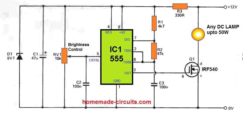
For a 555 based circuit you can try the following design:
The brightness control pot is actually the PWM control pot which translates into brightness control. The flashing frequency can be altered by changing the C3 capacitor value.
The IRF540 mosfet can be replaced with a TIP122 transistor.
D1 and C1 can be simply eliminated, since they do not have a crucial function.
The R3 can be reduced to 100 ohms for a 5V supply.
For charging your 3.7V cell you can use the following voltage regulator circuit:

You will have to adjust the zener value with some experimentation to make sure that the selected value produces an accurate 4.2V at the output side which can be used to charge your 3.7V cell.
And the transistor must be replaced with a TIP122 transistor.
So that’s it, these are probably the most compact circuit ideas which you can build using SMD parts to fulfill the specified application.
Let me know if you have any further doubts or queries.
Hi
I thank you for your patience in talking with me. Not sure if you noticed that I’ve seen stribes with 6) 5w Cree xpe series leds on one board 1″ x 1.5″ and powered by a 250mha lipo battery. I understand at 5v this is a 6A load which is quite a lot for that battery, yet the one i saw works well and the battery lasts 2 hours. I don’t know the duration of the flash, though I think the interval may be about 1 sec, maybe 1.5 sec.
I can send you a pic if helpful, if you wish to write me at my email of etbrown44@gmail.com
I could be open to engaging you to help me with this design if you are willing. I am not sure how the duration of the flash and frequency can be controlled without an ic, and I need a usb charging circuit for the battery.
Thanks Ernie
Hi, thanks for your explanation.
Pictures may not be required since I have understood your requirement and I will surely try to help you through this platform.
In the last circuit which we are discussing, the flashing frequency can be varied by adjusting the 100K preset which can be actually a 100K potentiometer.
And the frequency range can be further varied by selecting different capacitors for the 10uF/25V capacitors. Higher values would decrease the flashing frequency and vice versa.
If your battery is a 5V battery then it will require around 6V to charge fully, so a USB charging may not be possible since the maximum output from an USB is only 5V.
Hi
Many thanks for yoir kind reply!
The battery really is 250 mah. Im guessing it is 5 or 6v.
Ive seen a strobe like what i have in mind and they are powering 6) 5w cree xpe leds. 1000 lumens! Not sure their flash frequency or duration, but they get 2 hours of battery life.
With those leds, and that battery, can your schematic be revised to work.
Thanks Ernie
OK, no problem, the mAh rating simply indicates how much backup can be acquired from the battery.
You can still use the same circuit for your 5 W LEDs, except the 330 ohm resistor which could be reduced to 100 ohms or simply eliminated.
A 5w LED at 5 V would consume 5/5 = 1 amp current, so 6 LEDs would consume 6 amps which is too high for the 250 mAh battery. However since the LEDs would be flashing and not constantly lit, a 2 hour backup could be perhaps achieved, but I am not confident about it.
Hi
I wonder if your 36w schematic can be altered to be powered by a 250 mah lipo battery. ?? Voltage around 5v. Thinking of using 6) 5w Cree brand xpe series leds, for very bright strobe!
Kindly let me know what you think.
Thanks Ernie
Richmond Va
Hi, I guess your Lipo battery is rated at 2500 mAh, you mistakenly wrote it as 250 mAh. Yes, in that case it can be used. Since the voltage is just 5 V, the 330 ohms resistor could be perhaps reduced to 100 ohms.
Hi Swagatam,
In the 1st circuit, I want to use a 3.7V Li-Ion battery.
What changes do I have to do?
Hi Nelio, to use 3.7V in the first circuit you can remove the 330 ohms and connect the positive directly with the circuit. However, now you can use only one LED, and make sure to use a 100 ohm resistor in series with the LED.
Also, the preset is wrongly shown as 10K preset, it must be a 100K preset instead.
Hi Swagatam,
Ok.
Thank You
Best Regards.
You are welcome Nelio!
Hello, thanks for your circuit, and your explications, I’m planning to use strobe lights in my motorcycle, and I think your circuit will work, but my question is, do I need to use several circuits for each one of the bulbs, or one board can be used for the four bulbs.
Thanks in advance
Hi, glad you liked the circuit. You can use a single circuit to drive all the 4 bulbs, which will then strobe simultaneously.
Hi, I’m planning to build the circuit in the next days, I hope works fine. You’re doing a good job with this webpage. Thanks again.
My pleasure Arnold, all the best to you!
Mr. Swagatam,
I built a schematic of this in EasyEDA (not sure if you would like a copy of it) and put together a prototype of the schematic on a cheap breadboard off amazon. It works! (after a few hours of blundering attempts).
The issue that I have is that the 18 watt LED light that I am using is extremely dim. My power supply says that is it only drawing 0.036 amps and less then .5 watts @ 12.6 vdc.
When hooked up without the strobe circuit the light draws 1.2 amps and 15 watts @ 12.6 vdc.
Any suggestions on how to get this to produce more light?
Maybe it is just my cheap amazon breadboard? – I have the positive side of the light hooked directly to the power supply and I have bent up the coletor on the TIP142 with alligator clips so at least these are outside the breadboard…
When I plug the light directly into the breadboard leads I get 1.3 amps and 17 watts (for whatever reason it draws more amps thru the board than hooked directly to the light)
Any suggestions would be greatly appreciated!
Respect,
Donald
Hi Donald, is the driver transistor which powers the LED heating up too much? If it is heating up then it might blow off and cause the LED to be dim, if not then there could be a fault in your connections. If everything else is in good order, there can be only 3 reasons for the LED to get dim 1) The LED itself gets damaged due to over heating. 2) Transistor over heats and gets damaged, 3) Power supply fails to provide the required amount of current. It would be better to assemble the circuit by soldering instead of a beadboarding, to ensure 100% good connections.
Mr. Swagatam,
Thank you for sticking with me as I am working this thru.
Although I have not soldered it all together (I’m still working on that skill) I have purchased much better-quality components and have the strobe light working at 5 watts. (about a third of what it operates at without the circuit).
I have noticed that the TIP142 Transistor is getting hot after a few moments of operation. Do you think that has something to do with it?
Thanks again!
Donald
Hi Donald,
5 watts at 12V means the current will be = 5 / 12 = around 400 mA. This current is quite less for the TIP142 since it is rated to handle 10 amp current.
Are you sure the transistors are original and not duplicate.
Anyway you can consider adding a heatsink to the transistor if it is getting hot as the last resort.
As always sir, thank you for your advice!
My pleasure Donald.
Swagatam,
Thank you again for your help and quick response!
Could you enlighten me on the purpose of the “RED LED = 5mm 20mA type”?
Also, please pardon my ignorance, but what units is the “RX=.6/led current” in?
If I understand this correctly it would be .6 / 1.5amps = 0.4 somethings….Would this be a resister of 400Ω?
Thanks Again!
Hi Donald,
The red led is just an indicator LED which will flash along with the main LED.
RX is the current limiter resistor.
Yes your calculations are correct, but the result is a 0.4 Ohm resistor, not a 400 ohm
wattage of the resistor will be 0.6 x 1.5 = 0.9 watts or simply a 1 watt.
Thank you sir!
Mr. Swagatam,
I am new to working with circuit boards and I find your work both fascinating and helpful.
I am trying to create a security “blind light” that goes off with an alarm on a 12v system.
I am using a 18watt led light that draws about 1.5 amps but would like the option to add an additional light for a total of 3amps/ 36 watts.
I seems to me that your last diagram is precisely what I am looking for. Is there any possibility that you could decode the image for me into a parts list. I would like to build this but am not sure what parts I would need to order. Thank you soo much for your help and entertaining my requests!
Respect,
Donald
Thank you Donald,
You can definitely try the last design for your specified application
I have updated the parts list under the last diagram, as required by you. Hope it helps
Hi. I love the simplicity of what you’ve shown here and I’m hoping that I’m just being simple in my turn when looking at the diagrams.
I’m trying to make the strobe circuit for mains power to run the lamp on top of a full size police box (AKA TARDIS from Dr Who – I know, I know……). Anyway, I get most of the diagram for the mains powered lamp alternative except for the positive and earth wires. Do I need to add additional power into the circuit at those points or does it not already use the mains shown on the far right of the diagram to power it? Or (an here’s where it could well be me being simple) have you added those to indicate positive and negative orientation of the components?
Thanks – and apologies if I’m just being a little hard of thinking
Hi, thank you, and glad you liked the post! I guess you are referring to the following diagram:

Yes you will have to apply a DC between 5 and 12V across the (+) and the ground lines. The mains power is used only to drive the lamp through the triac. The transistor circuit will require an external DC to operate.
ok Swagatam,
The reason I ask for connecting the SMDs without soldering, is because I have heard there is some kind of special glue to do the job. You understand there is a tedious work to solder these tiny components together especially for a hobbyist.
One more thing.
Can I use those I already have, yellow SMD LED’s [0402 warm white] are coming pre-wired, or should I use any other type of LED’s?
And how I can identify the polarity +/- of those components [resistors, capacitors, transistors] etc., to complete the circuit you suggest?
Or it does not matter, I can solder them either way?
And finally once I complete the circuit, the strobe effect will continue to operate once I reverse the polarity of the supply power [i.e. put the locomotive on reverse] or should I install one more component to operate the strobe light on reverse?
Thanks man
Pat
Hi Pat,
I have no idea about how SMDs can be glued, soldering is perhaps a must for proper connections.
You can use any 20 mA LEDs for optimum brightness.
Resistors do not have polarity they can be connected any way round, only the LEDs and the electrolytic capacitors have polarity….I think you can easily find the information by doing an online search…there’s plenty of information available.
To ensure that the circuit works regardless of the input DC polarity, you may have to supply the DC to the circuit via a bridge rectifier. The positive and negative terminals of the bridge will go to the circuit supply lines, while the remaining two terminals of the bridge will connect with the input DC supply.
OK Swagatam thanks
Is any Bridge Rectifier with special electrical characteristics for this application I should buy? or any bridge rectifier will do the job.? Keep in mind I must build this circuit as small as possible.
I have order all components yesterday, except the bridge rectifiers.
I promise to send to you the results of the outcome.
Or my goof-ups……………!!!!
Hi Pat,
Any ordinary bridge rectifier will do. It may be SMD type or built using 4nos of 1N4148 diodes.
You can surely send me the results, hope it works for you as per the expectations.
Thank you Swagatam,
I have some old SMD Bridge Rectifiers (remove them from an old board) without the marks + and – on them.
Is any way to identify those marks +/- on these components by using a continuity check?
So I can use them instead of ordering new ones?
Thanks
Pat
No problem Pat, Yes you can use it. You may have to check each diode inside the bridge with a multimeter, and with some effort find out which are the two ends that have two anodes joined together and which are the two ends that have two cathodes joined together
Thanks Swagatam
I do appreciate ALL your help.
Waiting for the parts to arrive.
Pat
You are most welcome Pat!
Hi Swagatam,
Just run to your site and I wonder if you can help me converting a strobe LED light made for bike safety at night, using two of those round 3V batteries, to my DC or DCC HO locomotives that use 7 to 19 DC Volts.
In other words is any way to modify/bypass the 3 way push button switch (“ON-study lit”, “slow blinking” and “strobe”), and install this tiny chip with LED light(s), to my locomotive and get activated without any buttons to push, but once I apply power to the rail tracks and ONLY in the “strobe” mode?
On the other hand, if you have some easy schematic/diagram for something I am looking for to built, I will be glad to see it.
Regards
Pat
Hi Pat,
It can be difficult to modify the existing circuit without actually seeing its circuit diagram. If you are willing to build a new strobe light then I would recommend the first circuit which is a tested design, and quite easy to build and implement. For 19 V, you may have to put another 330 ohm resistor in series with the LEDs, if two LEDs are used in series. For a single LEd use a 1K series resistor.
Thank you Swagatam for your reply.
Now to understand as I wrote the supply voltage is various from 7DCV to 19DCV.
There is a transformer that regulates the voltage to the tracks accordingly to how fast of the locomotives run.
So, the additional 330 ohm resistor should be between the two LED’s?
For one LED you advise me to use1K resistor, instead of 330 ohm?
Because of limited space I have inside the loco shell one more question.
Is there any way to connect the SMD’s without soldering the parts, so to create a very tiny circuit?
Thanks in advance
Pat
Hi Pat, that’s correct, if 19V is the maximum that the circuit has to tolerate then you will have to put an additional 330 ohms in series with the LEDs (if two are used), or a 1K resistor if a single LED is used.
SMDs parts can be used, and that will allow you to get a very tiny little circuit. SMD will require soldering, they cannot be connected without soldering.
I need to make an array of 300 LED of 660nm chips of 0.5W each. And, I want that the full array can be strobed at the frequency of 1MHz, producing ON pulses of the minimum 1microsecond. Can you please suggest the kind of LED’s and the driving circuit best suitable for this application?
I think you should modify the last concept from the above article for your application. You can adjust the output frequency to the desired levels by adjusting the capacitor values suitably.
Thank you for all the wonderful designs. I’m interested in turning FEIT Electric WLR2000/2/RP LED work lights into strobe lights to humanely drive away unwanted squatters (squirrels and mice) in our attic. These white LED lights have the needed brightness but they are equipped with internal battery packs. I’d like to remove the battery packs and directly control them with one of your circuits. Please advise which of these circuits will be suitable for this application. Thank you.
You are welcome, can you please provide the voltage and current specifications of the LED module that you have mentioned? I will try to figure it out.
That LED module will probably not work since it has an internal non-replaceable Li-ion battery. I have found another device that fits into a 110V E26 light bulb socket and is rated at 120V/60Hz/80W so I will need a circuit in line with the switch. The circuit itself may be powered by a lower voltage (5V?) USB power supply if needed.
OK, in that case the circuit using the triac will work, but it won’t be isolated from mains AC, and therefore USB would be also floating with AC mains. To avoid this an opto coupler might be required between the triac gate and the DC circuit, but that would make the design much complex.
Thank you. Perhaps I didn’t explain clearly, I’m thinking the circuit you provided for Lloyd Chesney’s application above would work for me since my 80W LED light is powered by 110V. I assume this circuit can drive an 80W LED lamp. What power 12V power supply should I use for this circuit.
What’s the part number for 12V relay and the red & blue diodes connected to the 1K resistors on terminal 3 of IC 555?
What change should be made to adjust the strobe flashing frequency?
OK got it, however a relay based strobe light may not be a good idea, since that may subject the relay to a lot of wear and tear, due to rapid switching.
If you want to use it, you can try it. The relay can be any 12V relay with coil resistance of around 400 ohms
The 12V DC can be from any small 12V adapter.
R2 and R1 both can be experimented to adjust the strobe.
Thank you for all the examples. First I am hoping someone has a suggestions for a real world need for many of our elderly family members living in a standalone housing developments. I want to find/make a light switch to replace a conman on/off light switch. I want it to switch to have two operating states, one constant on – for everyday use and a second operating state of flashing to help emergency responder’s to find them quickly. Please let know if you have ideas or know of a product that can do this.
Glad you liked the ideas. Here’s a diagram which can be used for fulfilling the mentioned application:
Hi Swagatam
Thanks for your reply
I’m using the 2N2222 transistors only and are the parts shown in the second diagram the same as the parts list shown further down in this article after the fifth diagram
Thanks
Regards
Vee
That’s fine Vee,
2N2222 will be able to handle higher numbers of LEDs. Instead of using two potentiometers you can use just one, and replace the other one with a fixed resistor.
Hi Swagatam
In your first and second circuit diagram using a 12 volt supply how many white LED’s can I use in series or series//parallel
Regards
Vee
Hi Vee,
In the first diagram due to the presence of the series 330 Ohm with the positive line, you cannot use more than 6 LEDs (2 strings of 3 LEDs, in parallel)
However, in the second diagram you can use more than 12 LEDs (4 strings of 3 LEDs, in parallel, with series resistor of 1K on each string). You can increase the number even more by replacing the BC547 with 2N2222 or 8050 transistor.
Hello and thank you for your work and postings here.
I am looking to build a single (1) LED strobe (not flash or blink) that runs on 5VDC where I can control the pulse rate. I found this video and it looks to be the right time between nice defined strobes in the video but it was not when I built it, also the voltage is 12v not the required 5v I need. Could you please show me how to redesign this for 5V with the ability to control the strobe rate (looking for 1-1.5 seconds) please. Thank you.
You will need 12V for this circuit, 5V will not work, and it cannot be modified for 5V
https://www.homemade-circuits.com/how-to-make-single-transistor-led/
Hello,I would like a Simple as possible ?
Circuit diagram for a Variable frequency Strobe light using leds ?
I want to use it for various Physics experiments ?
Meldes,Water drop,Etc,etc
Thank you
Hi, you can try the circuit design which is shown in the video…
sir, is this the kind of capacitor your mean I should put for T1 and T2 Ceramic Capacitor 103 (0.01uF),
Capacitor 0.01uF = 10nF, code is
103/ 103z. pls don’t be bore with my question.
It is to be put in the calculator software for time T1, T2 slots.
sir thank u for your responds but I didn’t understand what u mean, but let me state it this way connect the positive of the astable circuit to the battery positive through a 100k ohm resistor and connect a 100/25v capacitor across the positive terminal of the circuit. and connect a IN4007 diode paraller to the capacitor which is the negative of the diode to positive line. positive of the diode to negative line,pls is this what u mean and as for the transistor astable calculator software, can you give me clue on how to make use of it .I will appreciate.
Hello younkking, It should be 100 ohms, not 100k. And the diode should be a 12V zener, not 1N4007.
Please refer to the following circuit, and check how the circuit side configured with the above mentioned parameters.
https://www.homemade-circuits.com/1500-watt-pwm-sinewave-inverter-circuit/
In the astable put 0.01 for T1, and T2, rest can be as already filled
good evening sir, I used this first circuit as an inverter which is light strobe circuit. the gate of the MOSFET (irf540)was connected to the collector .drain to the left side of the transformer and the other drain to the right side of the transformer while the center tap is for battery positive.but on powering the circuit, it light up 60 watts bulb for a seconds before blowing off bc547 transistor .the only thing I change in the circuit is 100k fixed resistors in place of preset. now what could caused the problem. does it mean that the MOSFET is not getting the need frequency or does it mean that the two halve wave is oscillating at the same time .cos the two led in your circuit is blinking at the same rate and I wish i know how to upload the video of this circuit so u can see the blinking rate before this issue arise.pls your respond is needed.
Hello youngking, it could have happened due to the transformers’s reverse EMF spike. Connect the positive of the astable circuit to the battery positive through a 100 ohm resistor, and connect a 100uF/25V capacitor across the +/- terminals of the circuit, and also connect a 1N4007 diode parallel to this capacitor, cathode to the positive line, anode to the negative.
…and you can use this software to set the frequency at 50 Hz:
https://www.homemade-circuits.com/transistor-astable-multivibrator-amv-calculator/
Thank you sir, i will still go back and apply what you said whenever i have time
hello sir, thanks for your effort so far . i went through the second diagram concerning where the gate should be connencted is in between R1 AND R4 or before R1 and R4 . the link you shown me about increasing the frequency, i scean through it yet i didn’t figure out anything. pls i really need your help on this few question above.
You can change the capacitor values to change the frequency. The mosfet does not need to be Darlington. Mosfet gate can be connected directly to the collectors.
since you have already tested the circuit with LEDs, the circuit has to oscillate and the transformer will make a low buzzing sound that will confirm its oscillating.
sir pls don’t be bore with my question. 1. so the gate of the mosfet will be connected to the output of this circuit where the Led bulb is .2. like you mention darlington iRf540 should be used can’t iRf3205 be use for the job. 3. the circuit was built with 9v battery, so what if one use 12v battery won’t it blow the whole circuit .4. what and what can be change in other to increase the frequency, because what i use is fixed resistor which 100k. 5. the diode you mention which side will be connected to the gate nor the source. 6. how will i know that the transformer is oscillating. I’m waiting for Ur respond
youngking,
please go to this article:
https://www.homemade-circuits.com/mini-50-watt-mosfet-inverter-circuit/
and check the second diagram for the details.
for frequency change you can refer to the following page:
https://www.homemade-circuits.com/transistor-astable-multivibrator-amv-calculator/
sir i build this first circuit and it work, so how can i use it as an inverter. sorry to quote you . I would recommend you to first build a basic astable circuit with LEDs as shown in the first diagram from this article and then apply it or the inverter function: don’t use VR1, use 100K for the base resistors initially so what next to do thanks.
Youngking, if you have confirmed with LEDs, so now you can link the Darlington power BJT or mosfet with the two halves of the astable. I would recommend IRF540 which can be directly linked with the collectors of the respective BJTs. Make sure to attach protection diodes across the D/S of the mosfets.
After this switch ON power and you’d find the transformer oscillating at the set slow rate, may be 1Hz. Now you can gradually increase the frequency to 50Hz and get the required results.
Swagatam,
Could you add the Resister value for the two resistors going to the TIP 122 Transistors? Thank you!
Todd
You can use any resistor between 1K and 10K since the TIP122 is a high gain transistor. I have not shown resistors for the LEDs, assuming they are 12V rated or they have their own internal protections.
Hello sir, I cant get a 100k pot in our local market. I got a rotary switch having six fixed similar resistors (switch used in small emergency led light pack as dimmer). Can I use this switch as a pot buy replacing all six resistor with 15k resistor (each step will increased by 15k ohm as switch rotate) for above circuit???
Hello Nitin, you can use the pot or the rotary switch with 15K resistors, both will work.
Hello sir, I want know why two pot are used?
Can use one fixed and one pot instead???
You can use one pot in the manner shown here:
https://www.homemade-circuits.com/make-this-electronic-mosquito-repeller/
Hello sir, can I use this strobe light circuit as a pwm for small dc motor ???
Hi Nitin, yes you can use, try the second design.
Does anyone have a good place to get the parts in order to make this? Also, approximately how much would the parts to make this cost? I was thinking more of the 120V version. The 120V version would allow me to take a bank of LEDs that is connected to 120V plug I plug into the wall…and in theory if I plug it into this circuit then this device into the wall, would cause that bank of LEDs to flash rather than be on steady, right?
Hi Wesley, In India the cost of the parts would be less than a dollar, not sure about other countries. Yes the last circuit would allow you to illuminate lamps specified to work with 120V AC
You can buy the parts from any online electronic spare parts store, although the shipping charges could be 20 times higher than the actual cost of the parts
Sir,
I have successfully built the 2nd circuit i it works but how can i make it blink slower and i have set the VR2 in maximum and its still blinking fast. Do i have to increase the 100k pot? thanks..
Paul
Paul, increase the two capacitors values proportionately, that will slow down the blinking rate….
Sir can i replace VR1 with a fixed resistor and can you suggest what values of resistor can i replace..
Thank you..
Paul
you can directly connect R3/R2 ends with the positive line, but make sure these are at least 22K
BTW Sir,
In the second circuit can i add a piezo buzzer? And can i remove the two leds connected at R4?
Thanks again.
Paul
yes you can remove the LeDs, and also add a buzzer in parallel with R1 or R4…the buzzer should be a piezo buzzer ready to use
Thank you very for the quick response
Thank you for helping us newbies..
Paul
you are welcome Paul!
Hello,
Which of this circuit well power 12v LED to use as signal blinker for a motorcycle? And as replacement for my broken flasher in my motorcycle?
Thanks..
Paul
you can use the second circuit for your purpose, replace the bulb with your 12 LED connections
Hi Sir, I am a begginer in this and don't even know about the symbols or short forms of parts used in the schematic diagram. So, please kindly help me in this. I am interested in making a simple Led strobe with simple parts. So plz sir kindly send me circuit diagram with full names of parts and their values. Bcoz i can't understand above circuits of strobe lights.I will be very thankful to you for helping me.
Hi Anshuman, here's the parts list for you
Parts List
RESISTORS, 1/4 WATT
R1, R4, R5 = 680 Ohms,
R2, R3 = 10K
POTENTIOMETER
VR1, VR2 = 100K pot
TRANSISTORS
T1, T2 = BC547,
T3, T4 = BC557
CAPACITORS (ELECTROLYTIC)
C1, C2 = 10uF/25V
Triac = BT136
LEDs = as per choice
Hii sir, I am interested in using your circuit for speed measurement( Application of Stroboscope) so will it work for flashing light at high frequency and provide sharp light pulses at variable rate I.e at 0.5 ms to 100 ms? Please It'll be so kind if u can help me…
Hi Yakub, yes it will definitely work…you can try the second design from top….make sure to connect a 1N4007 diode in series with the emitter of the PNP transistor to ensure total switch OFF of the connected lamp
Hi! i´m try to use this for an OFF/ROAD led cubes in my vehicle andmanage to make it work eleminating "R4" but still the leds do not illuminate to their maximun capacity and sometimes they stop being strobes, these led cubes are 12v but do not specifies the watts, Iknow they are hig wattage, could you please help me with this dilemma? thanks in advance
I use 1/2w resistance
use a large heatsink for TIP127
Hi, yes you can use the second circuit for getting the intended results.
HI, finally I know that the LED cubes are 12v 18w and i´m going to use two LED cubes, if I use the second circuit with the "TIP127" is going to work?
T3 should be TIP127 or as per the LED current
Please try the second circuit from top, replace the bulb with your LED, but make sure to add a calculated resistor in series otherwise your LED and the PNP transistor both might get damaged
you can also try the third circuit from top
the pulse width can be controlled through the shown pot, and the frequency by changing the capacitor values.
I've noticed that some strobe circuits are better than others. Better, I mean sharper transient response. I'm looking at the kind used in the strobascope applications. https://en.wikipedia.org/wiki/Stroboscope
I've created art using this concept and tried various strobes. The conventual novelty units work best, cell phone stobe apps do not. They seem to blur the visuals the conventual are crisp.
Can you tell me why and also point me in the direction of concept to make a working circuit with sharper transient response?
Thanks!
Did you try a simple PWM IC 555 based stroboscope circuit? or you can also try a NAND gate PWM circuit for generating absolutely sharp turn ON/OFF strobe effects
I'm interested in flashing an LED 80-100 times per second. How can I accomplish this? Thank you!! jasona111988@gmail.com
reduce C1/C2 and VR1/VR2 values…
Please give a suggestion..
Hey i tried 1st one and works perfect on 9v battery and if i connect them in my bike the bc547 gets heated and no blinking in bulbs..
use 1k for R1, R4 and if possible replace the BC547 transistors with 2N2222….
Thanks and it worked great..how to make them to blink twice one and twice other if we connecting them on other arm as you said above in comment?
thanks Bro! here's my email ID hitman2008@live.in
Cool super works by u 🙂 can u lend me ur email id i have some queries and i need to send pics?
sorry No, if you are using only the R4 channel then you should NOT remove R1 otherwise T1 will blow off.
yes you can 24V also but only if the strips are also rated at 24V
R1too it won't affect ics?btwn does it is reduce the brightness of the led due to less current? I already removed r4.. Does it works on 24v circuit too? Thnkz for the kind reply 🙂
…..2N2222 or 8050 have higher current rating therefore will not become warm or get damaged with higher current or voltages.
LED strips already have internal resistors so may be R1, R4 can be eliminated from the circuit.
2N2222 or 8050 are have higher current rating will not become warm or get damaged with higher current or voltages.
Yeah u r ryt it blown out…now works perfect as per ur diagram but brightness is low wt to do for it?i hv replaced two led and 680ohms into led strip..whats advantage of 2n2222 and 8050?how to check blown transistor? Btwn thnkz a lot finally my bike blinking:-)
led strips rated to work on 12V can be connected with the above circuit, change the transistors and check again, it seems the transistors are blown, replace them with 2N2222 or 8050
What should i do?also is it ok to replace the two led with led strip?
Hey bro when i connected this circuit the led is not blinking instead glowing steady also bc547 gets heated much
…make sure the resistor of the LED is connected with the positive and the LED with the collector for implementing the above integration.
if you have the LED connected to positive and resistor to the collector, just swap the positions.
For blinking it twice on each channel you may have to build another identical circuit, but without the collector resistors.
connect the collectors at the junction of the respective resistor and LED of the on each channel of the previous circuit.
adjust the new circuit to blink faster so that two blinks are injected on the LeDs.
Hello
Just came across your blog. Are these circuits free to use or there are any copyright issues???
Hello, Practical use is free and allowed, but publishing elsewhere could be an infringement
….T1, T2 = 2N2222
Hi, the third circuit would perfectly suit your need. LS1 may be replaced with the LED,
T4 = 2N2907
T3 = TIP32
R6 = 0.6/0.5 = 1.2 ohm it's the current limit for limiting the current to 500mA
rest everything would be as per the given parts list.
I'm an amateur with dc electrical circuits but quite fascinated and eager to try. I have been throwing around the idea of trying to build an electric fence charger. I think your strobe circuit would work. Would you agree? I need a constant on/off/on/off power source capable of delivering a high voltage shock while still not being strong enough to deliver permanent damage. These are the specs on a 2 mile fence charger.
Item Specifications:
115 volt, 60 cycle
AC input/output
0.5 joule output
Pulsed output
Output voltage no load is 2300 volts
2 mile range
I would like to build a tiny fence charger that would energize only about 50 ft. What do you think…is it possible?
….for making it tiny you can replace the ignition coil suggested in the above links with a small ferrite core transformer as used in mosquito zappers.
Yes the above circuit can be used with a fence charger for triggering short pulses, I have discussed one similar application which employs a 555IC producing identical results which also has an adjustable pulse rate feature, you can refer to the following two articles for getting an idea regarding the concepts:
https://www.homemade-circuits.com/2012/05/make-this-solar-powered-fence-charger.html
https://www.homemade-circuits.com/2011/12/homemade-fence-charger-energizer.html
I got a few questions for you. I am a volunteer fireman and I'm thinking about using your design here for some emergency lighting for my jeep. How could i wire in 2 strips of LEDs both containing 6 LEDs, and make them alternate? Also can this circuit work on a 12v DC circuit?
If you can email me about this I'm very interested in learning more.
Adam, yes making R2/R3 smaller will produce faster blinking rates so you can try replacing them with 1k resistors.
If the LEDs are not completely shutting off, the reason could be leaky caps or wrongly connected cap polarity.
If the caps are OK, you may try adding a series 50 ohm resistor with the LEDs to eliminate the issue or put 1N4007 diodes in series with the emitters of T1/T2
Hi Swagtam, OK, getting closer. My previous post probably didn't accurately describe what I'm trying to do. I have a vehicle 12v festoon LED bulb that I want to rapidly blink. I originally didn't understand what you meant by connecting between collector and positive (I thought you meant the positive base of the transistor, and blew it up) but understand now that you meant the positive rail at the top of the circuit.
OK, so I have removed R1 and R4. R2 and R3 are still the original 10k ohm resistor and the trim pots are still there at 100k ohm. I wired in the 12v LEDs where the original 3v LEDs are in the 1st circuit. Now I get the LEDs to light up, and dim slightly with a tweak of on of the trim pots, but no blink.
Should I take out R2 and R3? Should they be replaced with a smaller ohm resistor? One last piece of info is that the 12v festoon LEDs measure 88.7 ohms across.
Any help would be appreciated.
Adam
Hi, if the LEDs are rated to work with 12V, you may connect 6 of them in parallel across each transistor collector arm, they should work, but the transistor may need an upgradation and may be replaced with 8050
Hi, I followed your first circuit diagram on a breadboard and it worked perfectly. I'm truing to make a 12v circuit using 12 festoon LEDs with inbuilt resistors. I can't quite work out from your written description what to do. Can you draw it?
Hi, I have an interesting one for you. I am a bus driver and on my bus there is a ERG machine(ticket machine). Now, it has red and green led’s where you place your card. Goes green if you receive a ticket and red for a failure.
Anyway, when I put the ERG machine on standby all the led’s go out but are still lite when I look at them through the corner of my eye. Look at them direct, nothing. Look them indirect, all led’s light up.
What frequency is that and how can I replicate this. It fascinates me.
Hi, it is nothing but a negligible amount of current leaking through the LED. You can easily simulate it by connecting a LED to a 12V source with a 22K, or 33K, or a 100K resistor in series with the LED.
The above circuit will work with 12V supply.
You can use the first circuit with the following mods:
Connect LED on the other arm also but use three LED in the series.
You can accommodate another series of 3 on each arm with separate individual series resistors as done with the previous series, in this way you have six LEDs on each side.
If you have readymade strips with the above series built in, you can simply connect each strip directly between the collector and the positive of the transistor on each arm..R1 and R4 will not be required in that case.
he parts list would be:
R1, R4(for the first option) = 150 ohms
R2, R3 = 68K (the VR1/2 are not required, you can remove them and connect R2 R3 directly with the positive rail)
Capacitors = 10uF/25V
Transistors = BC547