A 50 watt inverter circuit might look quite trivial, but it can serve some useful purposes to you. When outdoors, this small power house can be used for operating small electronic gadgets, soldering iron, table top radios, incandescent lights, fans etc.
Let’s learn 2 homemade 50 watt inverter circuit designs, beginning with a brief description regarding the circuit diagram and its functioning:
Design#1: How it Works
The first 50 W circuit may be understood with the following points:
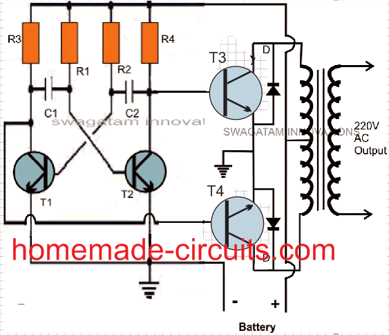
Referring to the figure below, transistors T1 and T2 along with the other R1, R2, R3 R4, C1 and C2 together form a simple astable multivibrator (AMV) circuit.
A transistor multivibrator circuit basically is composed of two symmetrical half stages, here its formed by the left and the right hand side transistor stages which conduct in tandem or in simple words the left and the right stages conduct alternately in a kind of a perpetual “motion”, generating a continuous flip flop action.
The above action is responsible of creating the required oscillations for our inverter circuit. The frequency of the oscillation is directly proportional to the values of the capacitors or/and the resistors at the base of each transistor.
Lowering the values of the capacitors increases the frequency while increasing the values of the resistors decreases the frequency and vice versa. Here the values are chosen so as to produce a stable frequency of 50 Hz.
Readers, who wish to alter the frequency to 60 Hz, may easily do it by just changing the capacitor values appropriately.
Transistors T3 and T4 are placed at the two output arms of the AMV circuit. These are high gain; high current Darlington paired transistors, used as the output devices for the present configuration.
The frequency from the AMV is fed to the base of T3 and T4 alternately which in turn switch the transformer secondary winding, dumping the entire battery power in the transformer winding.
This results in a fast magnetic induction switching across the transformer windings, resulting the required the mains voltage at the output of the transformer.
Parts Required
You will require the following components for making this 50 watt homemade inverter circuit:
| Component | Value |
|---|---|
| R1, R2 | 100K |
| R3, R4 | 330 Ohms |
| R5, R6 | 470 Ohms, 2 Watt |
| R7, R8 | 22 Ohms, 5 Watt |
| C1, C2 | 0.22 uF, Ceramic Disc |
| D1, D2 | 1N5402 or 1N5408 |
| T1, T2 | 8050 |
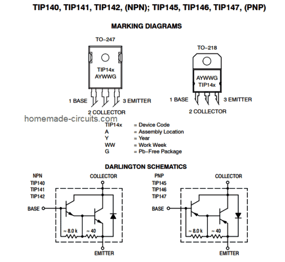
| T3, T4 | TIP142 |
General purpose PCB = cut into the desired size, approximately 5 by 4 inches should suffice.
Battery: 12 volts, Current not less than 10 AH.
Transformer = 9 – 0 – 9 volts, 5 Amps, Output winding may be 220 V or 120 volts as per your country specifications
Sundries: Metallic box, fuse holder, connecting cords, sockets etc
Testing and Setting Up the Circuit
After you finish making the above explained simple inverter circuit, you may do the testing of the unit in the following manner:
Initially do not connect the transformer or battery to the circuit.
Using a small DC power supply power the circuit.
If everything is done rightly, the circuit should start oscillating at the rated frequency of 50 Hz.
You can check this by connecting the prods of a frequency meter across T3’s or T4’s collector and the ground. The positive of the prod should go to the collector of the transistor.
If you don’t own a frequency meter, never mind, you do a rough checking by connecting a headphone pin across the above explained terminals of the circuit. If you hear a loud humming sound, will prove that your circuit is generating the required frequency output.
Now it’s time to integrate the battery and the transformer to the above circuit.
Connect everything as shown in the figure.
Connect a 40 watt incandescent lamp at the output of the transformer. And switch ON the battery to the circuit.
The bulb will immediately come ON brightly…..your homemade 50 watt inverter is ready and may be used as desired by for powering many small appliances whenever required.
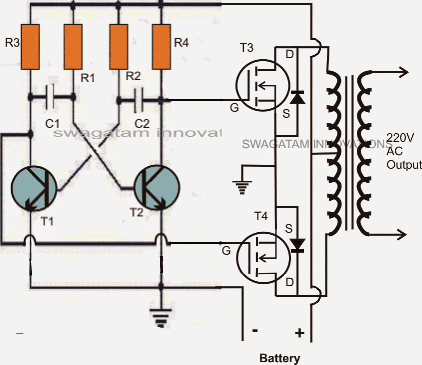
Design#2: 50 Watt Mosfet Inverter Circuit
The circuit explained above involved power transistors now let's see how the same concept may be utilized with mosfets making the configuration much easier and straightforward, yet more robust and powerful.
Rest of the stages are pretty much the same, in the earlier circuit we saw the involvement of a transistor based astable multivibrator for the generation of the required 50 Hz oscillations, here too we have incorporated a transitor operated AMV.
The earlier circuit had a couple of 2N3055 transistors at the output and as we all know driving power transistors efficiently requires proportionate amount of base drive, relative to the load current, because transistors depend on current drive rather than voltage drive, in contrast to mosfets.
Meaning, as the proposed load becomes higher, the base resistance of the relevant output transistor also gets dimensioned accordingly for enabling optimal amount of current to the base of the transistors,
Due to this obligation, in the previous design a additional driver stage had to be incorporated for facilitating better drive current to the 2N3055 transistors.
However when it comes to mosfets, this necessity becomes completely insignificant.
As can be seen in the given diagram, the AMV stage is instantly preceded by the relevant gates of the mosfets, because mosfets have very high input resistance, which means the AMV transistors wouldn't be unnecessarily loaded and therefore the frequency from the AMVwouldn't be distorted due to the integration of the power devices.
The mosfets are alternately switched, which in turn switches the battery voltage/current inside the secondary winding of the transformer.
The output of the transformer gets saturated delivering the expected 220V to the connected loads.
Parts List
| Component | Value |
|---|---|
| R1, R2 | 27K |
| R3, R4 | 220 Ohms |
| C1, C2 | 0.47uF/100V, metallized |
| T1, T2 | BC547 |
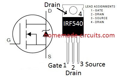
| T3, T4 | Any 30V, 10A N-channel MOSFET or a couple of IRF540 |
| Diodes | 1N5402 or any 3A rectifier diode |
Transformer = 9-0-9V, 8 amp
Battery = 12V,10AH
Video showing the Testing process of the 50 watt inverter circuit:


Questions & Answers
hi swag. what power transistor could i use to increase 50 watt inverter to 100 watt.
alsowhat the best way to test power output of inverter?
Hi Way, if you want to use power BJTs for 100 watt, then you will have to replace the output BJTs with Darlington combination of 2N2222 and TIP35…
hi swag
is thier an alternative to the 8050 transistors in the 50 watt inverter circuits?
Hey Way,
you can try 2N2222 or BD139 in place of 8050.
hello sir, I built the second circuit above, using 50n06 MOSFET , c1815 and ferite transformer but no output at the primary side of the transformer what could have cause it
thanks for responding
Hello Okon, please first check whether your transistor astable circuit is working or not? Disconnect the MOSFETs, and connect an oscilloscope across both the BJTs collector/emitter (one by one) and check the waveform. Make sure it is square wave.
If it is OK, then make a MOSFET tester jig and check if the MOSFETs are good or not, as explained in the following article:
https://www.homemade-circuits.com/how-to-check-mosfet-using-digital/
re the mosfet inverter. diodes should be fast recovery and the output needs a filter. this has nothing; not even a capacitor and the output will be nasty
The diodes does not need to be fast recovery since the inverters are 50 or 60 Hz rated. You can put a capacitor at the output, no big deal.
I am so happy to find this today. I have been looking for many years for a way to charge cordless phones directly from a DC source and up until now I have found it is not impossible to do without a energy wasting design of 12V to 120V and 120V to 6V inverter and adapter in line. Now since a cordless phone battery will not charge unless the 6 or 9V DC signal from the included AC adapter is pulsing, this means it is not as simply to e.g. look at the output of the transformer as “6V DC” and then simply provide a DC source from a battery (filtered supplies don’t work as it must be a pulsing DC).
Questions:
1) Can I grab a pulsing 6VDC or 9VDC (depending on supply power) by using only one output transistor and tapping onto that output, without the transformer?
2) Have you ever run into a 1:1 or a 1:2 transformer for sale (affordable) that could be used here where the power supplying the phone could be isolated? I know that I could use 2 transformers 6V to 120V and 120V back to 6V but I’m wanting to use the circuit that will be continuously running and powered from a small battery and wish to conserve energy as much as possible.
3) How much of a load would you anticipate that this circuit would draw “unloaded” with a) direct connected with no transformer or b) through a double step up/down transformer setup or c) if I can find a 1:1 or 1:2 wound transformer
Glad you are enjoying the articles.
1) Yes you can grab a pulsing supply, by attaching the intended load between the supply and the drain of one of the MOSFETs.
2) You can easily buy 1:1 transformer from any online store, it is readily available. However, the frequency of the circuit will need to be properly matched with the number of primary turns of the trafo.
3) The idle current consumption of the circuit will a) depend on the resistor at the drain of the other MOSFET. b)/c) will be significantly high compared to without a transformer.
I am building the simpler of the two circuits. Am very new to this sort of thing and have a very simple question before I check out the circuit –
Two of the leads, namely those from the emitters of all 4 transistors are shown as going to ground. I have always understood that ground is the same as the negative lead. Should they be connected to the -ve lead form the 12V battery (I note that the lead from the 8050 transistors does in fact connect with the -ve lead before the ground symbol is shown, but the lead from the two Darlington transistors is not shown so). If this is not the case, where should the connections go?
As a matter of interest, if this is the case, why is it shown the way it is – is this just a convention?
Yes the transistor emitters will go to the negative of the battery, which is the common line for the whole circuit. The negative sign on the battery indicates that it is the opposite of the positive. If you connect the voltmeter oppositely or with wrong polarity across the battery terminals, the meter will show the voltage in negative, and this explains why we have (-) sign on the battery negative terminal.
Good morning estimable Swag,
I need a simple inverter to work with 12V / 12Ah battery. I got a small, 12v to 12v12 satellite dish receiver, but I don’t know how many amps (any practical suggestions to know?). Could you get some 60W working with the IRF540?
Thanks
Hi Marcelo,
if the satellite dish receiver is 12V DC then an inverter will not be needed, you can directly power it from the battery, or may be I didn’t understand your requirement correctly.
Anyway for a simple inverter you can try any of the designs I have explained below:
https://www.homemade-circuits.com/7-simple-inverter-circuits/
The transformer is from an old receiver.
Please provide its specs.
12v-0-12v/2A
You can power the satellite receiver directly from the 12v battery
Hi Sir Swag, what i have with me is a 12-0-12, 0-220ac 7amps trafo, its a bit heavy, i want to make a simple inverter
that can power up a fan, a cfl lights, and a led bulb, using a single 12v 7-9ah battery. what do you suggest Sir?
i’m finish with your “20 watt fluorescent tube circuit” thanks to you Sir, but i want more lights with a simple inverter that you can suggest that can also last couple of hours with a single 12v battery. thanks!
Hi Amor, for this you can use an IC 4047 based inverter as given here:
https://www.homemade-circuits.com/2013/06/modifying-4047-ic-inverter-into-sine.html
But using a single 7Ah battery to run so many equipment can drain the battery quickly, and also shorten the life span of the battery!
Good morning sir, pls sir i build this circuit on a bread board yet it didn’t work , the R3 and R4 get bit warm each time i connect the battery . i use 9volt battery the one micro phone normaly use , although i didn’t see the capacitor you mention there in the market , therefore i use 474j capacitor .
i also use head phone to check the frequency yet nothing happen, although i didn’t have frequency meter. pls what could be the fault because i build this accroding ur diagarm
youngking, as you can see it is a very basic circuit, so it has to work and moreover it is a tested design. I would recommend you to first build a basic astable circuit with LEDs as shown in the first diagram from this article and then apply it or the inverter function:
https://www.homemade-circuits.com/2012/01/how-to-make-any-light-strobe-light.html
don’t use VR1, use 100K for the base resistors initially
good day sir , sir this second circuit that uses mosfet , the capacitor you mention as 0.47uf/100v metalized . 474j/100v was wirtten on it but they told me it is the one you mention in your diagram pls clear my doubt i ‘m confuse.
the capacitor which your shopkeeper has suggested is OK, and will work without issues
thank you for clearing by doubt
you said that the battery should be 7 ah does it mean that higher ah will not work. what if i use 12-0-12 transformer with higher amper will it still go
any desired battery with any Ah rating can be used, but the transformer and the mosfets will also need to be upgraded accordingly.
sir is about the first circuit that uses transistor, accroding to what you said.The earlier circuit had a couple of 2N3055 transistors at the output and as we all know driving power transistors efficiently requires proportionate amount of base drive, relative to the load current, because transistors depend on current drive rather than voltage drive, in contrast to mosfets.
Meaning, as the proposed load becomes higher, the base resistance of the relevant output transistor also gets dimensioned accordingly for enabling optimal amount of current to the base of the transistors,
Due to this obligation, in the previous design a additional driver stage had to be incorporated for facilitating better drive current to the 2N3055 transistors. does it mean that one have to employ bc557 as a driver. if i’m wrong pls can you explain what you mean because i’m don’t get. thanks
Youngking, what you are saying is absolutely correct, but in the first diagram I have removed the driver stage to keep the design as simple as possible., since the title of the article says “it’s for students”.
As far as current is concerned, the power transistors here are replaced with Darlington TIP142 transistors which are high current high gain BJTs, and therefore these are already enhanced to generate high current with minimal base currents, so that eliminates the need of an extra driver stage.
Can i use two different mosfet one is 37 amp other is 50 amp
yes you can!
Can i use 12k resistor and 2.2 uf cap for getting 50hz frequency
you will have to confirm the results practically with some experimentation
Can i use ferrite transformer instead of iron transformer?
The circuit is working perfect thanku
ferrite trafo will require high frequency, and high frequency cannot be used for driving home appliances so it cannot be possible, unless you apply additional complex stages
Sir why there is no resistor on the gate of the mosfet because there are resistor for mosfet in your ‘Single Transformer Inverter/Charger/Changeover Circuit.’
because we already have them in the form of R3/R4…so it’s not required
Can i use 13001 transistor instead of bc 547?. and what about the efficiency
it will work but it is unnecessarily huge for the application…
Sir can i use 70t036h smd mosfet it has 30v and 60 ampere capability
yes you an use it…
Hi sir, I have a similar design but different circuit, today after replacing the transformer and remaking the circuit with new parts, when I tested the output it should 225v but by replacing multimeter test probes sides, it showed 269v, why this difference in voltage showing after replacing multimeter probes side on output.
Hi Aabhishek,
I think your meter is malfunctioning, I would advise you to buy a good quality, costlier multimeter and check it with it. and I hope you are using the AC range of the meter.
Yes sir of course I’m using AC range, I know how to use it, ok thanks for advice I try to check this using different multimeter of Google quality. I pray to God that inverter is good just multimeter is malfunction.
Thanks.
Hi Aabhishek, inverter cannot be wrong, because it cannot produce two voltages together…it is the meter which is giving wrong results.
I made this inverter circuit but thee voltage drops too much when load is connected.
I have used 12-0-12 8A transformer and 12v 7ah battery.
check current by inserting a DC ammeter between the battery positive and inverter positive, and make sure the battery is fully charged at 14V.
the current reading will tell you whether the trafo is actually accepting the required amount of battery current or not. also check the voltage across the gate of each mosfet with reference to ground, it must be around 6V DC.
By the way the trafo should be 9-0-9V as mentioned in the article.
the output power will be as per the wattage of the transformer and the battery, upgrade these two to get higher wattage capacity at the output