In this post I have explained the construction of 3 simple electronic high frequency mosquito repellent circuits, which are specially designed to drive away mosquitoes through their tuned high frequency pulses.
Design#1: Using a Single CMOS IC
Mosquitoes are definitely a nuisance for your summer nights, especially when humidity prevails.
Electronic mosquito repellent techniques can come to your rescue to make, we hope, your sleep less restless.
Mosquitoes do not Like Certain Frequencies
According to recognized specialists, mosquitoes don't like certain frequencies. So, we have prepared a not very original but simple and inexpensive sound generator for them.
These frequencies will cause a lot of disturbance for the mosquitoes and ultimately drive them away. It is powered by three 1.5V button-type batteries and can be carried in your pocket.
The frequency range offered here is from 2 kHz to 28 kHz. The capacitor used is a ceramic model, which may be less precise than an MKT capacitor, but its precision is sufficient for this application.
How the Circuit Works
In our proposed electronic mosquito repellent circuit we have used a CMOS integrated circuit as an oscillator. This has the advantage of very low power consumption, an important quality for a portable device.
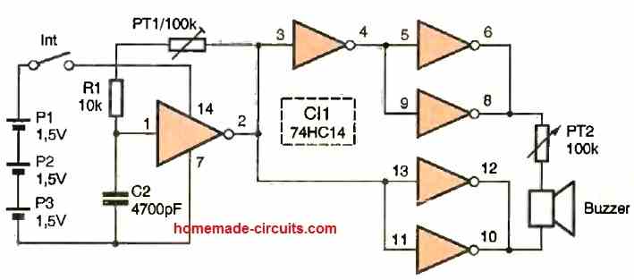
The output of the oscillator drives a pair of parallel triggers, effectively doubling the current capacity. The output is also inverted by a second trigger, which in turn controls another pair of triggers.
As a result, we have two signals in phase opposition at the output, which are sent to the piezoelectric transducer.
This bridge technique allows us to obtain a doubled output signal amplitude.
The amplitude of the signal will be equivalent to that of a circuit powered by a single 9V battery.
Here, we have added a potentiometer to adjust the level sent to the transducer.
The transducer has resonance properties and will produce a stronger signal at this frequency.
The power consumption of the circuit varies between 0.6 and 1.5 mA depending on the position of the potentiometer.
The circuit can operate for about fifty hours or more depending on the position of the potentiometer.
It can be easily carried in your pocket, making it portable and convenient to take it anywhere. Scouts, who are often bothered by these insects, will especially appreciate it.
The power supply using 1.5V batteries provides a voltage of 4.5V.
A decoupling capacitor filters the power supply and compensates for the high internal resistance of the batteries used here.
The oscillator uses a classic configuration and employs an inverting Schmitt trigger. The frequency is adjustable using the potentiometer.
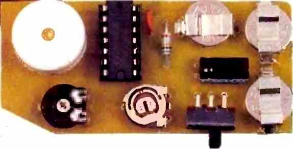
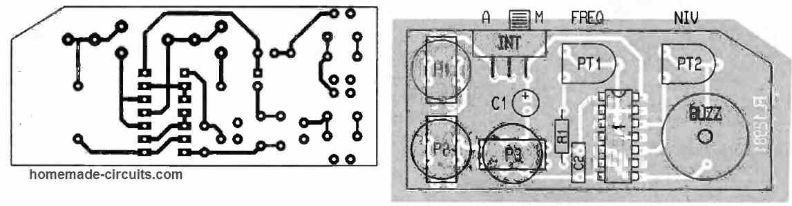
Construction
The printed circuit board has a special shape as it is designed to be installed in a DIPTAL 961 enclosure, a jerrican-type enclosure with a loop fastener.
The batteries are secured with soldered jumpers on tabs soldered onto the PCB. The integrated circuit socket is not necessary.
The transducer will be soldered once the enclosure is drilled.
We have provided a dual footprint for the potentiometers to accommodate smaller adjustable potentiometers.
The mechanical part of the assembly begins with cutting the switch.
Since the switch is recessed (to avoid accidental triggering), the material around the hole should be carved out (using a knife or a milling tool) to facilitate its manipulation.
Then, the circuit is installed at the bottom of the enclosure to locate the center of the transducer. If you don't want to embed it, you can simply make a carefully deburred hole of 4 to 5 mm in diameter.
Otherwise, you can make a larger hole using a milling tool or a mini drill, for example, or by using a 17 mm diameter wood drill bit handled with caution.
A hole of 2.5 mm in diameter is made before finishing with the drill.
Exterminator
As an additional feature, we have added an exterminator to this electronic mosquito repellent circuit.
We have not discovered a way to electronically exterminate these mosquitoes.
However, the enclosure's ring can be used to attach a sufficiently long elastic band, which can be used to hang the repellent or, if needed, to exterminate the creature, with the enclosure serving as a handle.
You remove the elastic band, aim at the animal, release the elastic band, and it's done.
The principle exploited here is the speed at which the projectile arrives and the small volume seen by the mosquito. It does not have time to fly away.
Design#2: Using Transistor Astable
Mosquitoes can be considered as one of the most irritating bugs that not only trouble us a lot but have the potentials of spreading deadly diseases.
These never seem to end, the more we find ways of eliminating them the more they come.
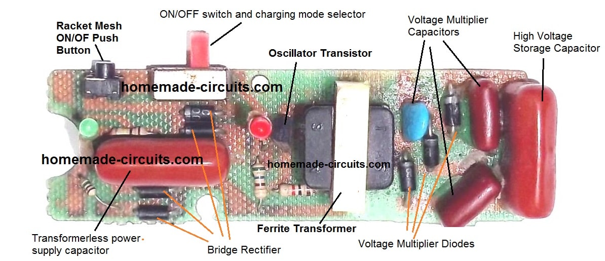
There are plenty of methods that have been developed today for tackling this issue, take for example the electrocuting bat, the mosquito repelling creams, coils, mats etc.
All of these may look effective but have never been the ideal method of termination.
However there is one more method which is though quite controversial may be considered as the most efficient ways of all, provided the results are accurately optimized.
Here we are discussing the method which probably is able to drive away the mosquitoes with the help of frequency generations.
Researchers have found that bugs and insects are typically allergenic to a certain spectrum of frequency level called the ultrasound frequency.
This frequency is beyond the hearing range of the humans, but can cause a lot of uneasiness to the insects and also to animals like dogs and cats.
Though it can be debatable, there have been scientists and many folks around who have found this method pretty useful for controlling mosquitoes.
One sample circuit has been presented here which has been specifically devised for generating sound at the ultra frequency levels.
Circuit Operation
The proposed electronic mosquito repellent circuit cannot be considered “the be all and the end all”, but definitely has plenty of space for experimentation.
If the settings are done impeccably, and hits the “bull’s eye”, you could be just lucky. The idea is very simple and involves below ordinary components.
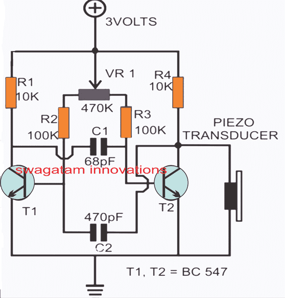
A couple of transistors and a couple of capacitors with some resistors is all you would need.
The circuit is configured as a astable multivibrator, the selected components set the circuit to oscillate at the intended frequency.
The slight imbalance with the symmetry (different capacitor values) of the circuit has been intentionally so that the generated waveform is symmetrical, another aspect that is important for implementing the proposed results successfully.
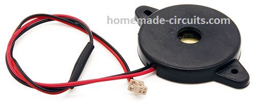
The frequency is outputted over a piezo electric transducer which is the best interpreters of frequencies, typically at very high levels.
The given pot should be tried at different levels and tested in a mosquito infested area, it may be further optimized until, hopefully some positive and encouraging effects are observed, meaning if you finally see the mosquitoes actually fleeing.
Piezo Transducer
Design#3 Mosquito Repellent Circuit using Crystal Earpiece
Mosquitoes and other toxic insects appear to only mate at specific periods, and outside of these times the sexes are extremely hostile to one another, staying well distant from one another.
It's also been proven that specifically the female are the ones that really stings.
The next thing we really have to understand is that the male mosquito (as well as other bugs) flaps its wings at a somewhat different rate than the female, which is major way these distinguish themselves.
It may be deduced from these nuggets of knowledge that if one electronically mimics the noise of a male mosquito wings, the females might flee.
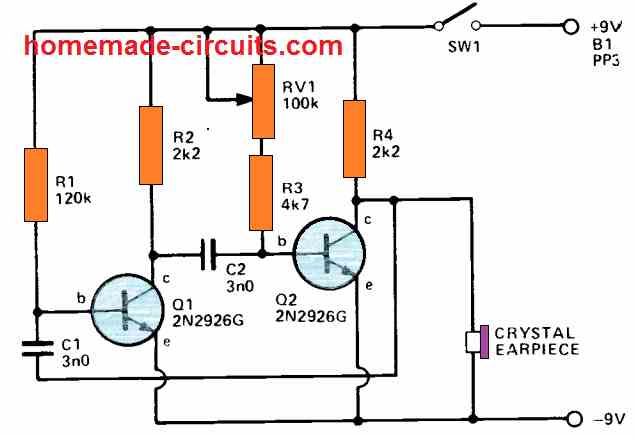
The mosquito repellent circuit depicted above is a basic audio oscillator whose operating frequency may be adjusted over a large range, to be precise from around 500Hz to 10kHz.
This value can be assumed to cover the frequency range of all typical bugs. The circuit is a simple multivibrator in which RV1 changes the audio frequency.
This generates a square wave, which is delivered across the tiny crystal earpiece linked to the negative line and the Q2 collector.
The impedance of crystal earpieces is quite high, although it has no effect on the circuit's performance.
This basic circuit may utilize almost any transistor, however if PNP types are employed, the battery supply must be inverted.
The capacitor values are not important. In case alternative capacitors values are tried and the frequency range is deemed to be inadequate, R1 may be modified to turn it back into the recommended range.
The current consumption is minimal (2-2mA) and fluctuates somewhat with frequency, however a PP3 battery might last a long time; after all, the device needs to be remain on for extended periods of time.
The device may be constructed in a tiny box to fit inside a coat pocket with the parts placed such that the earpiece becomes external, and all the components need to be as small as possible. It's a case of trial and error to find the correct frequency that rattles the mosquitos with highest efficieny.


Questions & Answers
Swagatam :
I make a circuit base on your Design 1 using a single CMOS IC , i am’ not find any C1 tank cap & cap ‘ s valve are ? thx for reply to me 😊
Hey JB, there’s no C1 in this circuit, C1 is mistakenly shown as C2, so there’s only one capacitor here which us 4700pF marked C2, but actually it should be C1….it is not my design, it was contributed by someone else…
Good morning Mr.swagatam,
iam facing the problem of entry of rats into my car engine compartment and chewing the wiring eventually causing frequent electrical problems. I saw a car rat repellent device in Amazon but is costing nearly rs 4000. Therefore, I request you to post or Design a circuit which can be helpful to overcome the problem. Thanking you
Good Morning BLV,
I think you should try the following circuit and check if it works or not to repel the rats away from your car:
https://www.homemade-circuits.com/rat-repellent-circuit-diagram/
Can this circle expel tarantula spiders!!??
You didn’t tell us how much bandwidth this circuit releases …!!!
Sir, what is the frequency range of the piezo transducer ?
It is around 40 kHz
hello can you be more specific on specification/ model of the piezo transducer ? thanks !!
Good morning sir, sir is about this Mosquito Repeller Circuit the transducer is of two type, the two terminal and three terminal. which one can serve the purpose. next for generating 20 herz frequence which value of resistor and capacitor can one use.
Youngking, Both will work, for 3 terminal piezo, ignore the center wire connection
Hello brother….
Did you test this circuit …
I was try some circuits like this one. but nothing any sucess.
nothing happend to mosquitos
please help…
Aruna
Hello Aruna, I personally have not tested it, but the circuit might work if the frequency perfectly matches the level that may be most disturbing for the mosquito.
Hello sir, can I use this circuit to run small 3v dc motor, with different speed like pwm??
Hi Nitin, yes you can try it in the transistor strobe light article, using the second design, not the above.
Pls can I power this circuit with 9v battery? And were you able to lay your hand on (Arun’s) same circuit?
you can try with a 9V supply, I am sorry I did not get any email from Mr. Arun regarding the concept so far…
Pls I need a circuit with two push button.if the first button is pressed the relay should open after 5min and it should remain that way even if the power is off and re-on,except the second button is pressed to changed the state of the relay to its normal state.pls help me.thanks
without power the circuit will reset, so it is difficult to create something that will continue to hold its state even without power….it will require a of thinking.
Pls can I power this circuit with 9v battery? And were you able to lay your hand on (Arun’s) same circuit?
Anyone did this do it works well?
Any body did this circuit and do it works well?
hi swagatam,
i am a farmer, and need a simple repelling device for use in agricultural equipment, so i can reduces insecticide use.
device features;
a. solar powered with rechargeable battery.
b. a multi pulse repeller, keeps changing the ultrasonic pulse it emits. prevent pests from getting used to the sound.
c. effective range: up to 5000sf.
d. ultrasonic frequency: from 13.5khz to 95khz.
e. dual speaker or more.
could you please help me with a circuit diagram?
thank you.
cia brisat
Hi Cia,
I'll try to design it and publish it soon in my blog.
I have snt u an email ( to hitman2008@….. ). Plz check it out sir.
Of course i will sir.
On searching the internet about this topic in deep, i got several verified projects based on this, one of those saying that at high frequencies , the insect will think that some sort of dragonfly is coming to catch them and will fly away from the area. I believe thz to an extend since this statement can be true. What z ur opinion about this ?
Would you mind telling me how much does the piezo buzzer costs ?
I hope it's true and you succeed with your project.
the cost of the recommended 27mm piezo element would be hardly some rupees, may be Rs.5/-
Sir,
First of all thank you very much for all your valuable supports given for my water controller project. It is working perfectly. Now i am in the middle of making multi insect repellent which can be used for repelling all types of insects, even dogs, cats etc could be repelled. Before proceeding further, let me ask you two questions:-
1). Have you heard about any insect repellent circuit which is completely functioning or any such products in market ?
2). What type or buzzer to be used for freq. upto 90 Khz ? Can an ordinary 8 ohm 0.5 W buzzer will function atleast in freq. range of 20-30 Khz ?
Expecting ur reply soon as b4.
Hi Arun,
congrats on your success!
I personally am very sceptical about this concept, according to me frequencies cannot drive away insects.
Standard speakers will not produce 90kHz, you can use piezo transducers for it.
Do let me know the results if you are actually trying out any such circuit.