In this post we will try to learn how to diagnose and repair an inverter, by comprehensively learning the various stages of an inverter, and how a basic inverter functions.
Before I have explained how to repair an inverter it would be important for you to first get fully informed regarding the basic functioning of an inverter and its stages. In the following content I have explained regarding the important aspects of an inverter.
Stages of an Inverter
As the name suggests DC to AC inverter is an electronic device which is able to "invert" a DC potential normally derived from a lead-acid battery into a stepped-up AC potential. The output from an inverter are normally quite comparable to the voltage that is found in our domestic AC Mains outlets.
Repairing sophisticated inverters are not easy due to their many involved complex stages and requires expertise in the field. Inverters which provide sine wave outputs or the ones which use PWM technology to generate modified sine wave can be difficult to diagnose and troubleshoot for the folks who are relatively new to electronics.
However, simpler inverter designs that involve basic operating principles can be repaired even by a person who is not specifically an expert with electronics.
Before we move into the fault finding details it would be important to discuss how does an inverter work and the different stages normally an inverter may comprise:
An inverter in its most basic form may be divided into three fundamental stages viz. oscillator, driver and the transformer output stage.
Oscillator:
This stage is basically responsible for the generation of oscillating pulses either through an IC circuit or a transistorized circuit.
These oscillations are basically the productions of alternate battery positive and negative (ground) voltage peaks with a particular specified frequency (number of positive peaks per second.) Such oscillations are generally in the form of square pillars and are termed as square waves, and the inverters operating with such oscillators are called square wave inverters.
The above generated square wave pulses though are too weak and can never be utilized to drive high current output transformers. Therefore these pulses are fed to the next amplifier stage for the required task.
For info on Inverter oscillators you can also refer to the complete tutorial which explains how to design an Inverter from the scratch
Booster or Amplifier (Driver):
Here the received oscillating frequency is suitably amplified to high current levels using either power transistors or Mosfets.
Though the boosted response is an AC, it is still at the battery supply voltage level and therefore cannot be used to operate electrical appliances which work at higher voltage AC potentials.
The amplified voltage is therefore finally applied to the output transformer secondary winding.
Output Power Transformer:
We all know how a transformer works; in AC/DC power supplies it is normally used to step-down the applied input mains AC to the lower specified AC levels through magnetic induction of its two windings.
In inverters a transformer is used for similar purpose but with just opposite orientation, i.e. here the low level AC from the above discussed electronic stages is applied to the secondary windings resulting in an induced stepped up voltage across the primary winding of the transformer.
This voltage is finally utilized for powering the various household electrical gadgets like lights, fans, mixers, soldering irons etc.
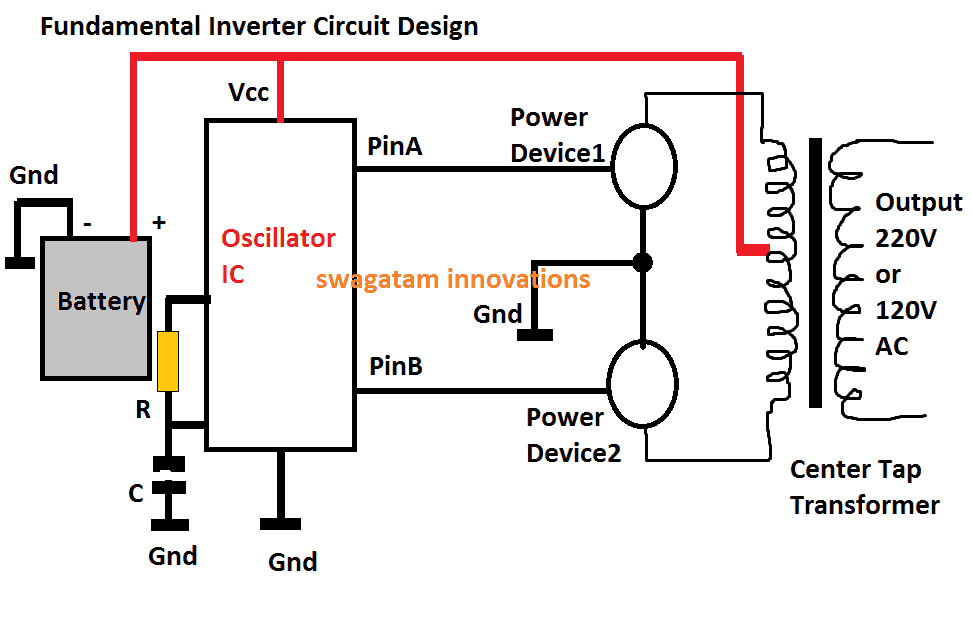
Basic Principle of Operation of an Inverter
The above diagram shows the most fundamental design of an inverter, the working principle becomes the back bone for all conventional inverter designs, from the simplest to the most sophisticated ones.
The functioning of the shown design may be understood from the following points:
1) The positive from the battery powers the oscillator IC (Vcc pin), and also the center tap of the transformer.
2) The oscillator IC when powered starts producing alternately switching Hi/lo pulses across its output pins PinA and PinB, at some given frequency rate, mostly at 50Hz, or 60Hz depending as per the country specs.
3) These pinouts can be seen connected with the relevant power devices #1, and #2, which could be mosfets or power BJTs.
3) At any instant when PinA is high, and PinB is low, the Power Device#1 is in the conducting mode, while Power Device#2 is held switched OFF.
4) This situation connects the upper tap of the transformer to ground via the power device#1, which in turn causes the battery positive to pass through upper half of the transformer, energizing this section of the transformer.
5) Identically, in the next instant when the pinB is high and PinA is low, the lower primary winding of the transformer becomes activated.
6) This cycle repeats continuously causing a push-pull high current conduction across the two halves of the transformer winding.
7) The above action within the transformer secondary causes an equivalent amount of voltage and current to switch across the secondary by means of magnetic induction, resulting in the production of the required 220V or the 120V AC across the secondary winding of the transformer, as indicated in the diagram.
DC to AC Inverter, Repairing Tips
In the above explanation a couple of things become very critical for obtaining correct results from an inverter.
1) First, the generation of the oscillations, due to which the power MOSFETs are switched ON/OFF, initiating the process of electromagnetic voltage induction across the primary/secondary winding of the transformer. Since the MOSFETs switch the primary of the transformer in a push-pull manner, this induces an alternating 220V or 120V AC across the secondary of the transformer.
2) The second important factor is the frequency of the oscillations, which is fixed as per the country’s specifications, for example countries that supply 230 V, generally have a working frequency of 50 Hz, in other countries where 120 V is specified mostly work at 60 Hz frequency.
3) Sophisticated electronic gadgets like TV sets, DVD players, computers etc. are never recommended to be operated with square wave inverters. The sharp rise and fall of the square waves are just not suitable for such applications.
4) However there are ways through more complex electronic circuits for modifying the square waves so that they become more favorable with the above discussed electronic equipment.
Inverters using further complex circuits are able to produce waveforms almost identical to the waveforms available at our domestic mains AC outlets.
How to Repair an Inverter
Once you get well versed with the different stages normally incorporated in an inverter unit as explained above, troubleshooting becomes relatively easy. The following tips will illustrate how to repair DC to AC inverter:
Inverter is “Dead”:
If your inverter is dead, do preliminary investigations such as checking battery voltage and connections, checking for a blown fuse, lose connections etc. If all these are OK, open the inverter outer cover and do the following steps:
1) Locate the oscillator section; disconnect its output from its MOSFET stage and using a frequency meter confirm whether or not it is generating the required frequency. Normally, for a 220V inverter this frequency will be 50 Hz, and for 120V inverter this will be 60 Hz. If your meter reads no frequency or a stable DC, it may indicate a possible fault with this oscillator stage. Check its IC and the associated components for the remedy.
2) In case you find the oscillator stage working fine, go for the next stage i.e. the current amplifier stage (power MOSFET). Isolate the MOSFETS from the transformer and check each device using a digital multimeter. Remember that you may have to completely remove the MOSFET or the BJT from the board while testing them with your DMM. If you find a particular device to be faulty, replace it with a new one, and check the response by switching ON the inverter. Preferably connect a high wattage DC bulb in series with the battery while testing the response, just to be on the safer side and prevent any undue damage to the battery
3) Occasionally, transformers can also become the major cause for a malfunction. You can check for an open winding or a loose internal connection in the associated transformer. If you find it to be suspicious, immediately change it with a new one.
Although it won't be that easy to learn everything about how to repair DC to AC inverter from this chapter itself, but definitely things will start "cooking" as you delve into the procedure through relentless practice, and some trial and error.
Still have doubts...feel free to post your specific questions here.




Questions & Answers
i have an Inverx 650 VA inverter overload at no load inverter.by mistake the phase output line connected to input phase supply after that the mosfet IRF 740 fleshed away after changing them only two were short circuited the inverter goes to permanently overloading at no load with red light i have no diagram for refernce.replacing the whole line Mosfet's in parallel or something else.
It would be difficult to guess without actually seeing the issue…so I am sorry can't figure out the problem from here.
Greetings Swagatam,
My inverter has burned up a capacitor and the board specifies a different cap than the original, should I change the cap to the requirement printed on the board or just us the same original was 250V 470uf board has 450V 330 uf printed on it in this location
Greetings Steven,
It's not critical according to me, you can use either of them, as per the availability.
Hello,
I have a Go Power 1500 inverter and was using 4 – 6v AGM batteries to power the RV. The inverter when turned on goes into it's start up procedure and when finished it goes immediately into overload. I installed 4 new (same) batteries and it continues to do the same thing.
I disconnected the inverter when the issue first happened and the batteries swelled and started smelling so I removed those too.
Is there a component inside the inverter that would make the inverter revert to overload even with brand new batteries and everything else is fine?
No tripped GFCI, or inline fuses blown etc.
I didn't open the cover and inspect for any burnt components yet and the inverter itself doesn't smell like a capacitor etc. has burned.
Is there anywhere that repairs these as Go Power doesn't repair their units so, I was forced to buy another inverter!
Thanks in advance.
An overload situation might occur only under two conditions, if the connected battery voltage is much higher than the specified limits, or if the output load exceeds its predetermined level.
As long as the battery voltage is correct and output is not over loaded, even 100s of batteries connected in parallel wouldn't cause any issues or tripping.
So, there's certainly some other serious issue with your inverter, not something which you can diagnose at home.
Ok, understood on the non home diagnosis of the unit. Where can I send it for repairs and what is the labor charge usually to repair it? I realize parts would be a cost too.
Go Power doesn't repair their own units as mentioned prior.
Thanks in advance.
I am sorry, I really do not have any information regarding this.
The power devices (mosfets) are the ones which might have got damaged, according to me
Hi Swagatam. My 5000W 12V to 230V PSW inverter's fan speeds up as the temperature of the unit rises (or as the amp draw increases, not sure which is the case). At lower speeds it will slow down as load or temp decreases, but if it reaches top speed, it gets "stuck" there and never returns, running at high speed, unless the unit is shut down and powered up again. How can I fix this to have it always return to lower speeds when it cools down?
Hi Andries, it will be difficult to diagnose because different models have different circuit topologies, and configurations, which are unique to those models, so it's not possible to troubleshoot without practically seeing it.
Hi, i have a 2500 watt 12volt/240volt inverter, on the same system i also have a generator which takes over when the batteries are low. I have 2 rotatry switches operating the electric, however as expected i turn the generator power while the inverter power was also live thus putting 240 volt power to the 240 volt supply from the inverter.
This tripped the breaker on the generator and although i have reset that the inverter now does not work.
It has illuminations lights on it, it makes a pulsing noise and there is a slight smell of burning although the fan still works.
What do you think? (not of me lol but of the inverter please)!!
Hi, although im not very sure, if the smell is from the inverter while it's in switched ON positioned would certainly indicate a damaged tramsformer winding, but if it's happening in OFF position then it would need some investigation to see exactly what's burning (lol)….most probably it's the inverter winding that might have gotten slightly damaged due to the generator voltage in-surge.
I have in the motorhome a 1000 W 12v to 220V (240) inverter which produces no more than AC 200 V from the 85 Ah leisure battery. On the engine switched on it goes down to even 183 V. Please advice what could be an issue
your batteries could be producing lower than optimal voltage or may be are not fully charged.
you could try verifying the same by replacing them with new batteries.
My issue with a ready-made inverter is not considered here. From the beginning, this inverter worked fine for charging, but always made capacitive-input devices behave erratically when plugged in. The trackpad on the laptop doesn't move the pointer on the screen properly, and has a lot of jitter. Problem disappears when the device is unplugged from inverter. And perhaps more dangerously, a particular USB charger plugged in the 120V outlet (I know it's an inefficient use of the inverter 😉 gave me a discharge from touching the metal case of the tablet. This charger doesn't have any issue when plugged in at home, even though the mains is ungrounded. Maybe it was the charger or simply static electricity build-up on me from repeatedly moving to and from the driver's seat.
Still, how would I know what could be at fault in this case? I have no oscilloscope to verify the waveform or possible spikes, though I'll see if I can build a USB one.
Selim, are you sure the inverter is generating the correct RMS voltage? you can confirm it by checking the output voltage with a multimeter set at AC 250V range.
If it shows over 150V, the high voltage could be causing the issues.
Or it may be due to the high amount of harmonics from the inverter.
Try adding a 0.22uF/400V capacitor right across the inverter output terminals and check the results.
Inverters normally do not have a neutral, they have an alternating phases coming out of both their outputs pins, that's very unlike our mains AC, this could be the cause of the slight shock that you are getting from the charger body.
Hello sir, i have a microtek inverter which was working nicely from couple of year but suddenly i got one problem……sometime its stop working and indication show for overload and fuse blow while its output load and fuse are ok……and when i restart the inverter then its working again……what is the reason behind this
hello my life,
it seems to be an internal circuit problem, which needs to be diagnosed by removing the circuit board and checking with a multimeter,,,,it would be difficult to troubleshoot by assuming.
Off grid small house system. The inverter is feeding 40v AC back over the 12v batteries. In this state, current positive terminal to ground is 8 u Amps, as measured with a multimeter. This is making 12v backup generator live to 40v ac and zaps someone when they go to start the generator. Also the 40v ac appears to be interfering (but I'm not certain) with various charging cycles from solar and wind controllers. Can you give some clues as to further fault-finding techniques or suggestions please?
I guess the 40AC is connected with the battery through a bridge and a voltage regulator, in that case the battery could be safe, but a human could feel the zap due to his body earth passage.
You can try isolating the 40AC to the battery section via a transformer, the primary could be rated at 40V and the secondary slightly above the battery voltage rating.
…a schematic could have helped to understand the situation in a better way.
Hello sir, i have a microtek inverter which was working nicely from couple of year but suddenly i got one problem….wen i start it or increase load on it…… it starts generating abnormally high sound and output voltage i very low but at that tym it blows CFLs and mobile chargers……. after few minutes it will behave normal
Hello Sharad,
The automatic voltage correction feature of the inverter seems to be malfunctioning, it will need to be diagnosed practically, can't suggest much without inspecting.
Hii I have a 800VA Inverter & 150Amp Battery attached to it. My inverter is not showing the charging signal and indirectly charging it by overcharging the battery. Few days ago I topped up my battery by distilled water and after that I found out that the battery is not charging and over that when check with tester current is being shown on both the terminal of the battery.
Plz let me know about the problem and give me some solution for it.
try charging the battery with an external battery charger unit and then connect it with the inverter, the fault could be with your inverter's charging system.
If the battery doesn't charge optimally through an external charger it would indicate a damaged or a sulfated battery and will need to be changed
Hi,
I used my 300W inverter (12Vdc to 230Vac) to power a double tube flourescent light fitting. The total wattage of the light fitting is 130W. The tubes lit up, but then after switching off the light fitting and then switching it back on, the inverter failed. There is a red LED indication on the inverter which means that there is a fault. What could I have blown? Could the high inrush current have blown some component, or could a switching surge have blown some component? What is the most likely component in the inverter that could fail due to the inductive load which I subjected it to?
Please reply soon, Riyaz
Hi, Normally a good inverter will not fail even if its outputs are short circuited, so a tube light should have noway affected its operations.
Can't say what might have happened to it without a practical examination, looks like a part failure inside..
Sir i want to make a 850va inverter at home i am studying but did not get idea please provide me a complete circuit diagram with component list.my id is raj100386@gmail.com thanks
Rajesh, do the assembly as per the given diagram, the IC is 4049 the transistors are made up of TIP122 and TIP35 pairs….the capacitor value is 0.01uF, the resistor value near the capacitor is 100k, the transistor base resistors are 10k each
Hello sir howcr u….
My problem is that i m having a luminous 800va inverter 150amp battery attached to it…it's charging led were not working…so when i was repairing that board..it touched in heat sink of mosfet…after that none of the led's are working…it's not a big issue but….main problem is that inverter giving low output voltage 150 volts…on load and on no load…i measured it's battery charging amperes…which is 12amps…i tried different battery but problem is same….are mosfet's blown up??? If yes how can i check them with multimeter….???
Hello nitin, if the output is low then it could mean a few of the fets are fried or working asymmetrically…check the amp without load by connecting an ammeter in series with battery positive…if it's high without load would confirm a serious fet malfunction
Hello sir…there are two series of 5-5 mosfets each in my inverter…so one mosfet was looking cracked…so i changed whole series of 5 which was chn 608 with chn 347…when i connected battery it was working…but whenever i put load on it…,it started switching power on off immediately…and its relay started making noise…i remove load…after few minutes…a mosfet fried again with a pop sound…and a little transistor 639 started smoking….can u determine what's the exactly problem ???
Wish u a happy diwali…
Hello Nitin, I think the oscillator stage is frozen in your inverter which is causing the mosfets to short circuit through the trafo winding….disconnect the mosfet and the power buffer stage from the board and check whether the oscillator is working or not.
Ok sir…i m gonna try it…and let u inform…
Hi Roger, I think the overload protection circuit could be malfunctioning, try to locate the overload cut off relay or the particular circuit section, remove it and then may be you can try troubleshooting the possible fault in it.
sir I'm jeylani,
I'm beginer bt I've interest to learn abt designing of ckts pls guide me
Jeylani, you can start posting your specific questions in this blog, I'll reply with solutions…
Sir Iam B.V.R
I have DC TO AC 200W pwr inverter(12V DC to 220V AC)(50HZ),I wanted to use this by solar pwr,So how much capacity of CCU and BAttery I can use in this circuit
Bathula, a 50 AH battery will do the job, however for much longer backup you can opt for a 100 AH or higher batteries.
hell sir,
my home inverter doesn't give output. when mains power cutoff, inverter indicates on position but, could't give output. battery rating 12V, 135AH. how can i identify the fault, how to solve the problem or how can i repair…..???
regards
Sushant
Hello Sushant,
there are two things which might be causing this problem:
battery power not reaching the inverter, battery not charged or the relay changeovers are faulty and not transferring the relevant power lines across the output
Hi! Hope you are doing fine. Can you help me with my power inverter? I have this TBE 1000W power inverter that was working fine until it made this long beeping sound. I removed it from the solar panel system and connected it directly to the battery and it still is making the beeping sound. The battery is fine because it is being used in another solar panel system. What could be the problem? Thanks in advance!
Hi, I am sorry it would be very difficult to diagnose or judge an internal fault of a system, because there could be several reasons for a particular faults, not possible without practically checking it.
Hi,
I have a Silverline 1000W inverter that made a smell and stopped working!
A visual inspection showed a pin burned and the IC plastic cracked on the SDC 7500 chip.
I was going to solder a DIL socket in and try a new IC but I can't seem to find one online.
Also would you know what sort of fault further downline might have taken this chip out. Its the Vcc pin 12.
It seems to be a difficult IC to source?
Would you have a circuit diagram of this inverter?
Your comments greatly appreciated,
Kev
Hi, I compared the pinouts of your inverter IC with a more commonly available IC TL494 and they looked exactly similar.
So I think you can try replacing the burned SDC7500 with a TL494 and check the response.
However I can be difficult to understand or judge the actual reason behind this damage, because normally the supply to the electronic stage is always regulated and through a step down transformer.
I have a simple inverter version which is comparable to the one that you are using, if you have previously built electronic circuits then probably building this one from the start won't be a problem for you, here's the design:
https://www.homemade-circuits.com/2015/05/simplest-pwm-modified-sine-wave.html
Hello, could you tell me in 3 lines what is the main difference between repairing inverter and non inverter air condition ? I do not find an easy explanation to tell to someone else. Thank you.
An inverter in an air conditioner is used to control the speed of the compressor motor to drive variable refrigerant flow in an air conditioning system to regulate the conditioned-space temperature.
By contrast, traditional air conditioners regulate temperature by using a compressor that is periodically either working at maximum capacity or switched off entirely
hi i have an inverter which indicating faulty yet i have replaced all the mosfet with new one what might be the problem pliz assist.
without sufficient tips regarding the inverter circuit and the fault it would be difficult to judge the issue…