In this article I have explained a simple variable regulated voltage power supply circuit which utilizes just a single transistor. The design can be very handy for the new electronic hobbyist
Main Features
The explained power supply includes an adjustable voltage feature which is an essential feature for every electronic enthusiast. However making one such power supply within minutes using a handful of components might look difficult.
The circuit of a simple variable voltage power supply using just a single transistor referred here shows us how to build one such unit quickly using common parts from your junk box.
This single BJT regulated Power Supply is easy to construct. It takes less than an hour on a piece of copper-laminate.
All the components can be mounted as show in the aforesaid diagram, cutting the strips for placement.
Moreover the board also acts as a heat-sink. Enamelled wires are used to connect the components and the transistor gets bolted to the board, acting as a cooling agent.
Circuit Operation
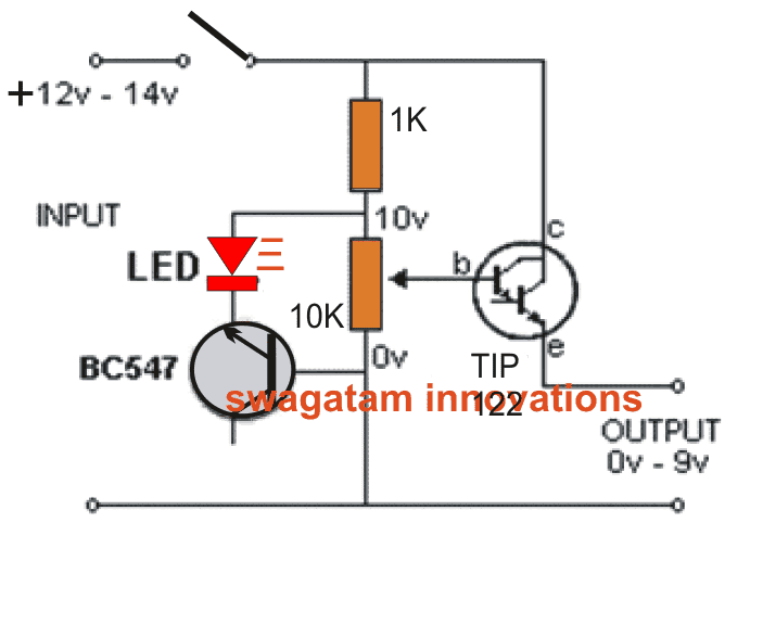
The circuit is designed for use with old C," "D", and even lantern batteries. That’s the reason for no diodes or electrolytic. Get some old batteries and connect together to receive 12v – 14v, at least.
The power for this output is controlled by a 10v zener, made by following the characteristic of zener voltage of 8.2v in between the base-emitter leads of a BC547 transistor, in a reversed bias, and 1.7v approx. across one Red LED. The circuit is designed to deliver 0v-9v at 500mA.
However the deliverance depends upon the life of the cells being used. The 10k pot works to adjust the output voltage and thereby the LED circuit goes in ON state.
A good part is that the circuit is well designed to fetch the last leg of energy from old cells.
Submitted By: Dhrubajyoti Biswas
Circuit Diagram


Questions & Answers
Dear Sir Swagatam
Hello. Thank you again for your kind feedback. Never forget your great favor.
Wish you all the best
Best regards
Ali
My pleasure, dear Ali!
Sir engineer Swagatam
Hello again. You made me very ashamed with your great favor. Thank you very much sir. I’ll do as you have instructed about how to use 2N2222, and will solder the negative side of a 8.2 V Zener diode to base of the BC547, and positive side of it to the positive lead of LED. Do you know you are a very patient and kind man who respond so patiently to guys with poor knowledge of electronics?
Never forget your kindness, Sir Swagatam
Bye
You are welcome Nassim.
I think you are confused with the 8.2V zener. It is not required at all.
The BC547 transistor itself works like a 8.2V zener.
If you want to remove the BC547 and the LED, then you can use a separate 8.2V zener and connect its cathode to the 1K bottom end and anode to ground
Sir engineer Swagatam
Thank you very much for so soon answering my questions. According to your response, I will use a 2N2222 instead of BC547 and will solder the negative side of a 8.2 V Zener diode to the base of the 2N2222, and positive lead of it to the positive lead of LED. Am I right Sir?
Wish you all the best dear Sir
Best regards
Nassim
Hello Nassim, the BC547/LED can remain as it is. The 2N2222 will need to be added with the 2N3055 for making a Darlington. Please see the following diagram for the details:
Sir engineer Swagatam
Hello. Hope you are healthy and fine. I am in need of doing this simple project because of bursting 2 power transistors of my bench power supply; but my problem is as follow:
1. At line 5 of the text under title “circuit operation”, you have mentioned using 8.2 V Zener diode which is not drawn in the circuit. Please tell me how to use it if it is vital.
2. If i want to use 2N3055 for Tip122, what would be the amounts of resistors. What about 2SD198,2SD200,BDY25. I have few of each.
I need your help dear
best regards
Nassim
Hello Nassim,
The above article was not written by me, and the diagram was not designed by me, so I may not be able to confirm the design operations. However, it seems that the 10V zener is with reference to the BC547 and the LED together, which works like a 10V zever diode. 8.2V is dropped by the BC547 and 1.2 V is dropped by the LED.
2N3055 alone will not be able to provide enough current due to its low gain. You may have to use another BJT, maybe a 2n2222 to form a Darlington pair with the 2n3055, for getting optimal current output. Resistor values will remain the same.
Thank u sir
Hai sir….
Output it will give constant current 1v to 9v…
For example 1v 200ma 5v 290ma 9v 500ma…
While varying voltage the current will be constant or it will vary…
1v to 9v same constant current
Or it will change ?
Hi Kesav, if your transformer is rated at over 500mA @ 9V then the output from the circuit will be constant 500mA throuout 0-9V range