In this post I will try to explain how an accelerometer works and also learn the specifications of a popular accelerometer ADXL335 in detail.
If you are a tech enthusiast you would have came across the term called “Accelerometer”.
This piece of technology made our smart phones really smart, many common home appliances, automobile, robotics, image stabilization, and much more gadgets utilizes accelerometer. In this article I have explained what an accelerometer is and how to use one for a project.
What is an Accelerometer?
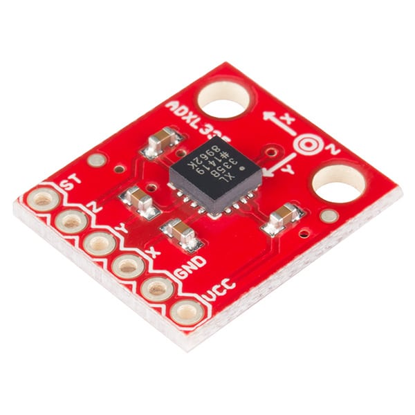
An accelerometer is a sensory electronic device that measure acceleration deceleration of a moving body or a vibrating body. Accelerometer comes in surface mount form, looks pretty much like an IC.
Accelerometers are embedded in our Smartphone which tells orientation of the phone, thus your image on your screen rotates accordingly.
Have you ever wondered how you’re racing car on your Smartphone moves left and right when you tilt your phone from left to right? It’s all possible due to accelerometer.
Triple Axis Accelerometer ADXL33 - Specifications
It measures 4mm x 1.45mm, just around size of a coin. It can measure in three directions X, Y and Z axis. It can be powered from 1.8 V to 3.6 V and power consumption is merely 350 micro amperes (uA).
It can survive up to 10,000 G of force (This means it can handle the acceleration of 10,000 times of its own weight).
It has working temperature range of -55 degree Celsius to +125 degree Celsius (absolute maximum).
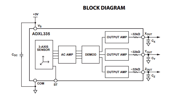
It has 6-pins, three of which are X, Y and Z axis output, two of them are Vcc and ground and remaining one is ST (self-test). At the three outputs connecting a 0.1 micro farad capacitors are recommended (on each axis) for ant-aliasing and noise reduction.
How an Accelerometer Works:
The following explanation can be studied to learn how an accelerometer works
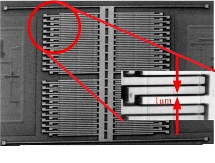
An accelerometer is a Micro-electromechanical system or simply (MEMS).
There are moving parts inside an accelerometer which detect changes in acceleration.
Capacitance is the key concept utilized in an accelerometer.
There are dielectric and metallic plates arranged in parallel manner attached with moving mass.
Three such modules are placed orthogonally each other. All the parallel plates are capable of moving independently. Each modules measure at one axis.
When accelerometer is tilted, due to moving mass, alignment of capacitor plates changes which alters the capacitance value. These changes are measured by built in circuitry and outputs an analogue signal.
The signals from accelerometer can be given to a microcontroller or a microprocessor depending on your design and application.
Applications:
There is huge spectrum of application ranging from mobile phone to satellite systems.
Accelerometers are ideally used in Smartphones where it is used to detect the orientation of the phone.
Accelerometer is boon for aerodynamics where airplanes need to be stabilized during flight.
Used in anti-theft devices where walking behavior is unique for all, this data is analyzed and stored, when there is any change in walking behavior, this can be detected.
Accelerometers are used in health equipment such as fitness band, pedometer etc. It is used in toys such as RC based helicopters and gaming controllers.
Accelerometer is very crucial component in satellite system where it needs to measure the apogee situation.
Questions & Answers
Can u kindly explain how can this sensor be used without any micro-controller or aurdino? It would be of great help.
It seems it can be used without microcontrollers also, what exactly do you intend to build with this accelerometer?
Basically the requirement of my project is to build a vibration sensor by using an accelerometer as the vibration sensor which does not use any kind of micro controller and arduino? It would be of great help if u can suggest any outcome as i am unable to think of any by myself??
You can connect 1N4148 diodes on the X, Y, Z output pins of the IC, then join the cathode ends of the diodes and use the common output to drive a transistor relay circuit.
Will there be any need of the Cx Cy and Cz capacitors or they are must?
Yes they must be included since they are a part of the circuit….
Can be this Accelerometer be used in marking ( reading) the track of any object for ptototyping like in CNC milling
the above accelerometer is a tilt based sensor, so it cannot be used for detecting a movements across a single axis,