In this post I have elaborately explained how to build simple transformerless LED bulb circuits using many LEDs in series and powering them through current controlled capacitive power supply circuit.
Safety Note: These circuits operate directly from mains AC voltage without galvanic isolation, meaning live components carry high voltage when energized. Standard electrical safety practices must be strictly followed during assembly and testing to prevent accidental contact. The author assumes no liability for compliance with safety procedures or handling errors.
Want to Build your own LED Drivers? Read this post on How to Design LED Drivers.
Capacitive LED Bulb with Many Series LEDs
The next circuit of a LED bulb explained below is easy to build and the circuit is fairly reliable and long lasting.
The reasonably smart surge protection feature included in the circuit ensures an ideal shielding of the unit from all electrical power ON surges.
How the Circuit Functions
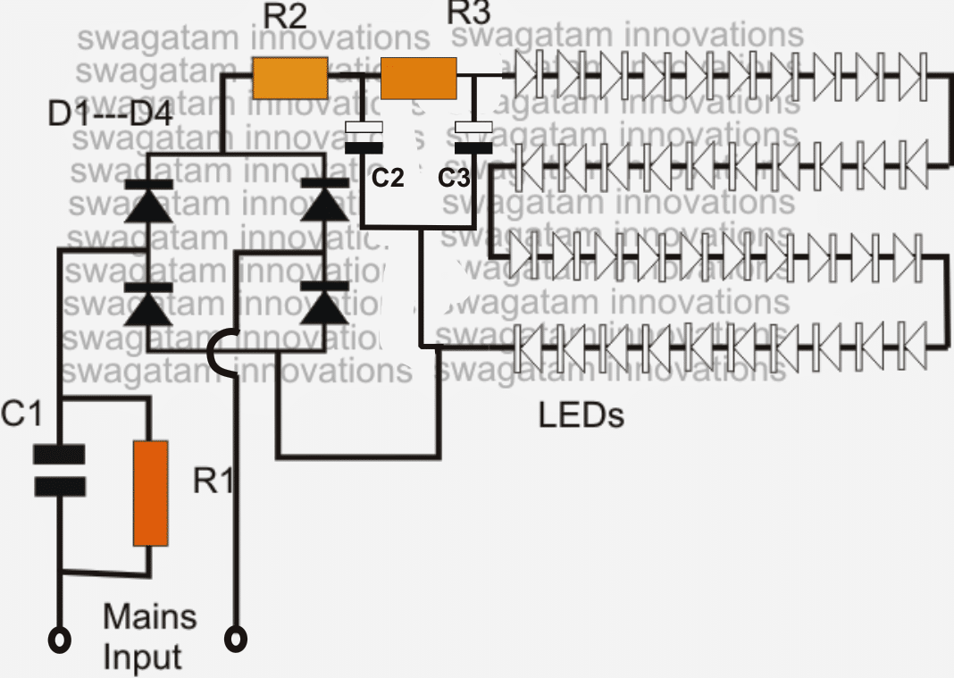
- The diagram shows a single long series of LEDs connected one behind the other to form a long LED chain.
- To be precise we see that basically 40 LEDs have been used which are connected in series. Actually for a 220V input, you could probably invorporate around 90 LEDs in series, and for 120V input around 45 would suffice.
- These figures are obtained by dividing the rectified 310V DC (from 220V AC) by the forward voltage of the LED.
- Therefore, 310/3.3 = 93 numbers, and for 120V inputs it's calculated as 150/3.3 = 45 numbers. Remember as we go on reducing the number of LEDs below these figures, the risk of switch ON surge increases proportionately, and vice versa.
- The power supply circuit used for powering this array is derived from a high voltage capacitor, whose reactance value is optimized for stepping down the high current input to a lower current suitable for the circuit.
- The two resistors and a capacitor at the at the positive supply are positioned for suppressing the initial power ON surge and other fluctuations during voltage fluctuations. In fact the real surge correction is done by C2 introduced after the bridge (in between R2 and R3).
- All instantaneous voltage surges are effectively sunk by this capacitor, providing a clean and safe voltage to the integrated LEDs at the next stage of the circuit.
Circuit Diagram#1
Parts List
- R1 = 1M 1/4 watt
- R2, R3 = 100 Ohms 1watt,
- C1 = 474/400V or 0.5uF/400V PPC
- C2, C3 = 4.7uF/250V
- D1---D4 = 1N4007
- All LEDs = white 5mm straw-hat type input = 220/120V mains...
The above design lacks a genuine surge protection feature and therefore could be severely prone to damage in the long run....in order to safeguard and guarantee the design against all sorts of surge and transients
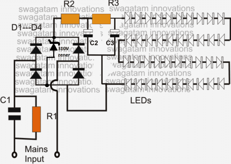
The LEDs in the above discussed LED lamp circuit can be also protected and their life increased by adding a zener diode across the supply lines as shown in the following image.
The zener value shown is 310V/2 watt, and is suitable if the LED light includes around 93 to 96V LEDs. For other lower number of LED strings, simply reduce the zener value as per the total forward voltage calculation of the LED string.
For example if a 50 LED string is used, multiply 50 with the forward drop of each LED that is 3.3 V which gives 50 x 3.3 = 165V, therefore a 170V zener will keep the LED well protected from any sort of voltage surge or fluctuations....and so on
Video clip showing an LED circuit circuit using 108 numbers of LED (two 54 LED series strings connected in parallel)
90 LED Bulb Transformerless, using Capacitor Power Supply
Warning: This circuit is not isolated from mains, so be extremely careful while testing it in switched ON position, to avoid a fatal electric shock. The whole assembly must be housed inside a sturdy plastic container for proper safety. BUILD IT ONLY IF YOU FULLY AWARE OF THE DANGERS OF ELECTRIC SHOCK AND KNOW HOW TO TAKE THE NECESSARY PRECAUTIONS AGAINST IT.
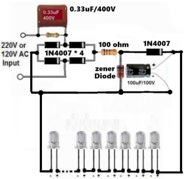
An LED bulb circuit can be a very intriguing project to build for any beginner or a school student, since this homemade project can be so useful and could be used for illuminating homes during night.
Although, the commercial LED bulbs are more sophisticated and employ an SMPS circuit, nevertheless the below shown LED bulb circuit could be built using capacitive power supply which is also equally efficient.
Note that the circuit can be customized as desired and any number of LEDs can be connected depending on the input AC supply level. For 220V, the number of LEDs can be up to 90 LEDs, and for 120V AC input the LEDs can be up to 45 nos.
The zener diode value will be equal to the value of the total forward voltage drop of the LEDs. For example if 90 LEDs are used then.
Total FWD drop = 90 x 3.3 = 297V.
So the zener diode value can be rated at 300 V.
Remember that the filter electrolytic filter capacitor value must be at least 25V higher than the zener value, if higher values than this is used, that will be fine.
High Watt LED Bulb using 1 watt LEDs and Capacitor
A simple high power LED bulb can be built using 3 or 4nos 1 watt LEDs in series, although the LEDs would be operated only at their 30% capacity, still the illumination will be amazingly high compared to the ordinary 20mA/5mm LEDs as shown below.
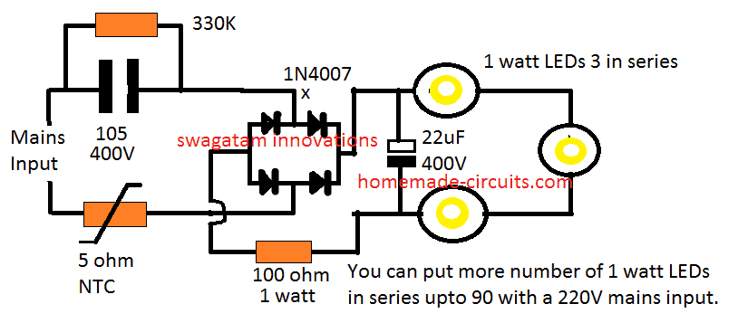
Moreover you won't require a heatsink for the LEDs since these are being operated at only 30% of their actual capacity.
Likewise, by joining 90nos of 1 watt LEDs in the above design you could achieve a 25 watt high bright, highly efficient bulb.
You may think that getting 25 watt from 90 LEDs is "inefficient", but actually it is not.
Because these 90nos of 1 watt LEDs would be running at 70% less current, and therefore at zero stress level, which would allow them to last almost forever.
Next, these would be comfortably working without a heatsink, so the entire design could be configured into a much compact unit.
No heatsink also means minimum effort and time consumed for the construction. So all these benefits ultimately makes this 25 watt LED more efficient and cost effective than the traditional approach.
Circuit Diagram#2
Surge Controlled Voltage Regulation
If you require an improved or a confirmed surge control and voltage regulation for the LED bulb, then the following shunt regulator could be applied with the above 3 watt LED design:
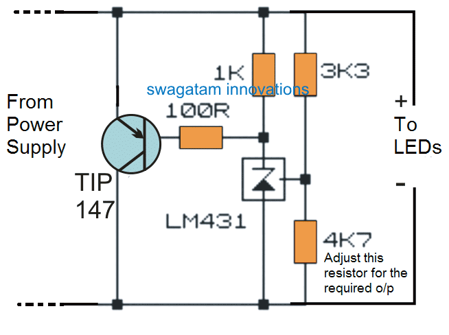
Video Clip:
In the videos above I have purposely flickered the LEDs by twitching the supply wire just to test ensure that the circuit is 100% surge proof.
UPDATE:
After doing a lot of research in the field of cheap LED bulbs, I could finally come up with a universal cheap yet reliable circuit that ensures a fail-proof safety to the LED series without involving costly SMPS topology. Here's the finalized design for you all:
These designs incorporate constant current and current limiting feature which makes them highly reliable, efficient and long lasting LED bulbs, and moreover they are extremely cheap compared to the commercial bulbs.
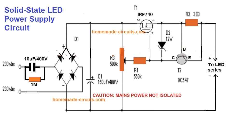
You just have to adjust the pot to set the output according to the total forward drop of the LED series string.
Meaning, if the total voltage of the LED series is say 3.3V x 50nos = 165V, then adjust the pot to get this output level and then connect it with the LED string.
This will instantly illuminate the LEDs at full brightness and with complete over voltage and over current or surge inrush current protections.
R2 can be calculated using the formula: 0.6 / Max LED current Limit
Improving the above Design
Although the above simple current controlled MOSFET LED driver looks easy and safe for illuminating high watt LEDs, it has one serious drawback.
The MOSFET can generate a lot of heat if the output is adjusted for low voltage LED strings.
The heat dissipation is basically due to the bridge rectifier and the C1 which converts the full AC cycle to DC, causing a lot of stress on the MOSFETs.
This aspect can be improved drastically by replacing the bridge rectifier with a single diode and moving the C1 capacitor parallel to the output LED, as shown in the following diagram:
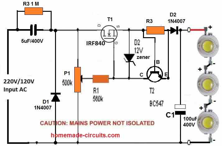
In the above diagram due to the presence a single diode D1 only half AC cycles are delivered across the MOSFET, causing 50% less stress and heat dissipation on the MOSFET.
However, the capacitor C1 parallel to the LED string ensures that the LED keeps getting the required power even during the absence of the other AC half cycles.
You can add more number of LEDs in series, a maximum upto 300 / 3.3 = 90 LEDs.
Make sure to adjust the P1 pot accordingly to adjust the output voltage to match the LED string's max forward voltage.
Likewise adjust the base/emitter resistor of T2 (BC547) to match the LED max current spec.
Using BJTs
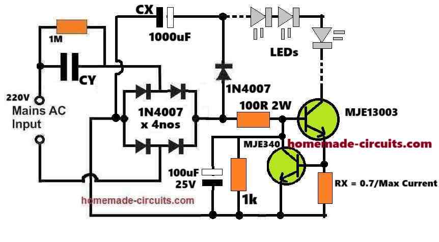
If you do not want to incorporate a MOSFET, then you can simply build the above design using BJTs as shown below:
How it Works
The main feature and operation of the design is controlling current and providing a safe constant current supply to the LEDs.
So we know, if the current is restricted then the LEDs can never burn regardless of the input supply voltage.
In this design, the capacitor CY does the main current limiting operation for the LEDs. Meaning, the reactance of the capacitor produces a resistance which limits the input 220V AC current to the maximum desired limit of the LEDs.
So, if the required maximum LED current is 300 mA, then you can select and adjust the value of the CY to ensure that it never allows the input current to exceed the 300 mA.
But if the CY capacitor itself can control the current for the LEDs, then why do we need the BJT current control stage, won't it be redundant?
The BJT current controller is necessary because the input AC 220V or 120V is never constant. If the input supply rises then CY will also start passing proportionally higher amounts of current to the LEDs, eventually causing damage to the LEDs.
The BJT current controller stage makes sure that even if the input AC supply happens to increase, it limits the excess current and ensures a constant current for the LEDs consistently and safely.
Moreover this BJT current controller stage also controls the switch ON in rush current making sure the LEDs are never subjected to any form of dangerous current inputs from the AC mains.
Calculating the Part Values:
Provided Data:
Input Voltage: 220V AC
LED Configuration: Let' us assume, 50 LEDs are in series
- Forward voltage per LED(VF) = 3.3V
- Total forward voltage VLEDs = 50 * 3.3=165V
LED Current Requirement: 300 mA (0.3A)
Capacitor CX: Acts as a filter for rectified DC voltage
CY: Limits the AC current to 300 mA
Transistors (MJE13003 and MJE340): Used as current regulators
Resistor RX: Used to calculate current regulation
Step 1: Capacitor CY for Current Limiting
The current through CY depends on its capacitive reactance XCX and the input AC voltage.
The formula is:
ICY = VAC / XC
Where:
XC = 1 / (2 * π * f * C)
For 50Hz mains frequency:
CCY = ICY / (2 * π * f * VAC)
Substitute:
CCY = 0.3 / (2 * π * 50 * 220)
CCY = 4.33 µF
Select CY = 4.7 µF (400V AC-rated).
Step 2: Resistor RX for Current Regulation
The resistor RX determines the current through the BJTs. The formula is:
RX = VBE / ILED
Where:
- VBE is the base-emitter voltage drop of the BJTs, typically 0.7V.
Substitute:
RX = 0.7 / 0.3
RX = 2.33 Ω
Select RX = 2.2Ω (5W-rated for safety).
Step 3: Filter Capacitor CX
The filter capacitor CX smooths the rectified DC voltage. Its value depends on the LED current and ripple voltage. Use the formula:
CX = ILED / (2 * π * f * Vripple)
Assume Vripple = 5V:
CX = 0.3 / (2 * π * 50 * 5)
CX = 191 µF
The voltage rating of CX must be higher than the total forward voltage of the LEDs, which is 165V.
Select CX = 191 µF (200V-rated). 1000uF is not required as shown in the diagram.
Step 4: Calculating the MJE13003 Base Resistor (100 Ω is wrongly shown in the diagram)
Collector Current (IC): 300 mA (LED current).
Current Gain (hFE) of MJE13003:
Typical hFE for the MJE13003 is around 8 to 10 at IC = 0.3A. Let’s use hFE = 10 as a conservative value.
Base Current (IB) Requirement:
The base current is given by:
IB = IC / hFE
Substituting:
IB = 0.3 / 10 = 0.03 A (30 mA)
Base-Emitter Voltage (VBE):
The base-emitter drop for MJE13003 is typically 0.7V.
Available Base Drive Voltage:
We will assume that the circuit supplies 165V rectified DC (across the LEDs and CX), because of the current limiting the 310V DC peak voltage from the 220V AC RMS will be forced to drop to the level of the LED total forward drop value. So, let us assume a standard voltage available at the base resistor is 165V.
Base Resistor Value (RB)
The base resistor limits the base current. Using Ohm's law:
RB = (Vbase - VBE) / IB
Where:
- Vbase = 165 V
- VBE = 0.7 V
- IB = 30 mA
Substituting:
RB = (165 - 0.7) / 0.03
RB = 164.3 / 0.03 = 5476.67 Ω
Power Rating of Resistor
The power dissipated by the resistor is:
PR = IB2 * RB
Substituting:
PR = (0.03)2 * 5476.67
PR = 0.09 * 5476.67 = 492.9 mW
Select a resistor with a slightly higher power rating for safety.
Resistor Value: Closest standard value = 5.6 kΩ.
Power Rating: 1W or higher (to handle power dissipation safely).
Step 5: Voltage Ratings of Components
Diodes (1N4007):
- Voltage rating: 1000V
- Current rating: 1A (sufficient for 300 mA)
Transistors:
- MJE13003: Suitable for high voltage switching
- MJE340: Handles low-side switching
LED Voltage Drop:
- Total forward voltage: 165V
- Ensure capacitor CX and diodes can handle this voltage
Finalized Component Values:
- CY = 4.7 µF (400V AC-rated)
- CX = 191 µF (200V-rated)
- RX = 2.2Ω (5W-rated)
- MJE13003 Base Resistor = 5.6 k (100 Ω is wrongly shown in the diagram)
- 1N4007 diodes: 4 pieces for rectification
- MJE13003: High-voltage transistor
- MJE340: Low-side current regulator



Questions & Answers
Hello,
I stumbled across this blog post recently and it remembered me about a Philips LED bulb I disassembled a while ago. Attached you can find a schematic which I’ve drawn from memory. I was wondering how it would perform compared to the demonstrated circuits above. How robust and long lived will it be? What are your thoughts?
Best,
Valentin
Hi, thanks for visiting this site and for posting the Phillips LED bulb circuit diagram. The design you provided is a basic constant current LED bulb circuit. However, the designs presented in the above article are better and are capable of providing more comprehensive current control, brightness and safety to the LEDs.
70 led bulb connect to series one led value 0.60w
plz send mi circuit diagram and part value
You can try the following circuit to power the 70 LED series LED, with some modifications:
https://www.homemade-circuits.com/wp-content/uploads/2023/03/improved-transformerless-power-supply.jpg
1) Please replace the C1 capacitor with a 0.33uF/400V
2) Replace the zener diode with a 220V / 1 watt zener diode.
Remember, since the circuit is not isolated from AC mains the whole wiring can carry lethal AC mains voltages. Please build it only if you exactly know how to correctly insulate the circuit using plastic covers and plastic sleeves. Do it at your own risk
Sir can u pls give the 200leds series circuit diagram
Hello Subhrajyoti, adding 200 LEDs in series with a 220V AC supply may not be feasible, instead you can use two parallel LED strings, each having 100 LEDs in series.
Let me know if that’s OK with you or not.
High Watt LED Bulb using 1 watt LEDs and Capacitor
Firstly thank you for all your doing for this community. Its a great help. My query is:
If I am to make a 25 watt bulb with 75x1W LED, what changes do I have to make to the components.
Thank you and look forward to your reply
Best regards
Suren
You can try the following simple design. You may have to adjust the 100 ohm resistor slightly to improve the brightness on the LEDs. Also make sure to use a 250V 1 watt zener diode parallel to the 22uF/400V capacitor. You can use many 12 V or 24 V zener diodes in series so that the total sum of the zener value is around 250 v.
https://www.homemade-circuits.com/wp-content/uploads/2012/04/1-watt-led.png
sir,namaskaar 3 one watt led circuit mein 5ohm ntc ki Maan kaise nikala aur kya ye circuit ke liye surakshit hai kripya bataye
I LITERALLY DO NOT UNDERSTAND ANYTHING
Ashu,
Please ask in English language only so that all can read and understand your question.
NTC value can be 5 ohm, it does not any calculations, since the current and voltage is auto adjusting in the 3 watt LED diagram.
If you use a zener diode then you can use the following formula for the NTC
NTC = zener value – total LED forward voltage / LED current.
Thank you for your reply. Much appreciated.
You are welcome!
there are many wifi dimmers based i.e. on ESP32 for the LED stip (5V or 12V), but I would like to use AC 230V LED stip (around 90 LEDs), with the same functionality: ESP32 inside and then on/off plus dimming – your circuit if fully passive and require pot to operate – do you have a project for WiFi operated dimmer?
thx
Sorry, presently I do not have a WiFi operated dimmer circuit in this blog.
I seek suitable module for 4vLED to be powered from 220v AC for spot light to be used by Students as study support.
Are you sure it is 4V? because LEDs are normally rated at 3.3 V. Also please provide the current rating of the LED, I will try to figure out the circuit
I have placed order on Amazon for” Electronicspices 4V 50 LED aluminium Strip Light Bulbs, Multicolour” at present this is max input i can suppliment.
OK, I checked it, but I could not get the current specifications of the board. I am assuming the LED are rated 20 mA each. In that case the total current requirement of the board will be 20 x 50 = 1000 mA or 1 amp.
You can use any mobile charger to illuminate the board through a series resistor.
The value of the resistor can be calculated with the following equation:
R = Mobile voltage – LED voltage / LED current
R = 5 – 4 / 1 = 1 Ohm 1 watt
So you can use a 1 ohm 1 watt resistor in series with any of the two wires of the mobile charger and connect it to the LED board.
Hi,
I’ve prepared the first circuit
But the mosfet got too hot and burned in 15 seconds (without heatsink)
Then I’ve added a heatsink to the mosfet and nothing has changed its still so very hot it cant last long.
What is the problem? (My driving current is aprox. 550-600mA)
Hi,
please provide LED current rating and the mosfet number….I hope the voltage of each LED is 3.3V. The zener diode value must be 12V.
The mosfet may be getting too hot due to the input/output difference which is very large…..if you increase the number of series LED to 50, 60, or 90. the mosfet be get cooler proportionately.
You either have to increase the number of LEDs, or decrease the input capacitor value, or add two or 3 mosfets in parallel
Thank you very much for your response.
at 1 and 2, i really got these. Thanks.
at 3) Where did we find this 6V value ?
Just as BJTs require 0.6 to 0.7V to turn ON, mosfets require around 5 to 7 V to begin turning ON….so the source voltage may lag behind the gate voltage by 6V
Thank you for your response.
Ima beginner
1) Where did we find this 0.6V value?
2) What is the purpose of the 12V zener diode in the circuit?
3) Please if possible may you explain little bit the circuit after the potansiometer? (Including Mosfet ,Zener , Transistor etc.) I couldnt figure it out completely.
(Again if possible, i think, it will be better if you add little more detailed explanation to the article about this last updated LED driver for the newbies like us.Thank you very much.)
1) 0.6 is the voltage level around which most BJTs, like BC547 will switch ON.
2) The 12V zener safeguards the mosfet gate by clamping the gate at 12V and avoiding excess voltage to it.
3) The mosfet is configured as a common source in which the source side voltage will be always 6 V lower than the gate voltage….so whatever voltage is supplied by the potentiometer at the gate of the mosfet, the same is replicated at the source side minus 6 V. The BC547 stage acts as a current limiter.
Is there any benefit for us of this 6V difference between the gate and the source? Or there isnt?
There’s no benefit, it is actually a drawback since the source load always gets 6V less than the gate voltage
At first circuit design;
1) ” R2 can be calculated using the formula: 0.6 / Max LED current Limit ”
Can you explain that more detailed?
2) What is the purpose of the BC547 transistor?
R2 is selected so that it develops 0.6V across itself whenever an over current is detected. This 0.6V will activate the BC547 which will short the gate/source of the mosfet shutting it off.
Can anyone Suggest best circuit diagram to control 2 LED’s blinking in 3 Modes i.e. When we press a button both glow continuously, when we press again both LED’s start Blinking & finally when pressed again Alternate blinking of both LEDs.
This can be done through an Arduino only, analogue circuit can be too complicated.
I am trying to figure out how to improve the existing power supply on chandelier in my house. There are 58 number of LED straw hat type in string connected to power supply. I find the LED burn out often on switch off/on. I have drawn the connections based on PCB. I can send photo of the connections of various components if I can get your email Id
It’s probably due to a capacitive power supply involved with the LED circuit. If an SMPS circuit is used this problem will never happen.
For sending an image you can upload it to any “free image hosting site” and provide the link to me. I will check it out.
Make sure to remove the http otherwise the comment will be sent to the spam folder.
The polarities of D1—D4 in the diagram are incorrect. The polarities should be just the opposite.
Please connect the zener diode D5 to protect the LEDs from damage. The value of the zener voltage will depend on the total series forward voltage drop of the LEDs
The zener is also vulnerable to the current surges, but here it is protected by R3, so nothing to worry.
R4 can be replaced with a jumper wire.
I will definitely try your suggestion. Based on number of led 58, 58 x 3.3 = 191.4 , zener 190v 2w rating should suffice. Please confirm.
yes, that looks perfect to me, you can go ahead with a 190 V 2 watt zener diode.
Is it possible to make a 25 watts led with a life time warranty.(I mean it would last for like more than 20 years)
yes that’s possible, if the zener diode is correctly selected and correctly rated
Hello sir I have run 20 1 watt led from 2nd. Circuit diagram but in the circuit 100 ohms 1 watt resistor is heating too much wat will be the solution for that pls tell thank you
Abdul the first and the second circuits are for 20 mA LEDs. You can use the second circuit by replacing the R2, R3 resistors with 10 ohm 2 watt each resistors. For the zener use a 70 V zener 5 watt.
For the input capacitor use a 5 uF/400V capacitor
sir i want transformerless suply for high led street light circuit details. in emergency i wat use them. Also spd circuit design for led lights and how to conncnt LDR in led light in internal or external.
Hello Sir, I want to build a 9watt led bulb driver at low cost. Can you please suggest any.
Rahul, please provide the voltage rating of the LED
I have an emergency light consisting of 90 led
Inside I found one circuit board but it is damaged
This board is not available in my country, can I use a board attached to another emergency light but it illuminates 60cm fluorescent lamp
With a modification in circuit
Sorry for my poor experience and knowledge
The fluorescent driver cannot be used to replace the LED driver, unless the voltage and current parameters are correctly matched.
I’ve been told by my course director that I need to design driver circuit for led used on domestic and commercial lighting.
but I don’t know where is the challenge.
do you have any advice or what can I do ? or what are the difference?
many thanks
What is the wattage specification of the LED that you intend to apply?
There is no specific Watts.
You can try this circuit
https://www.homemade-circuits.com/simple-220v-smps-buck-converter-circuit/