In this post I have elaborately explained how to build simple transformerless LED bulb circuits using many LEDs in series and powering them through current controlled capacitive power supply circuit.
Warning: Circuits I have explained below are not isolated from mains AC, and therefore are extremely dangerous to touch in the powered and open condition. You should be extremely careful while building and testing these circuits, and make sure to take the necessary safety precautions. The author cannot be held responsible for any mishap due to the negligence of the user.
Want to Build your own LED Drivers? Read this post on How to Design LED Drivers.
UPDATE:
After doing a lot of research in the field of cheap LED bulbs, I could finally come up with a universal cheap yet reliable circuit that ensures a fail-proof safety to the LED series without involving costly SMPS topology. Here's the finalized design for you all:
These designs incorporate constant current and current limiting feature which makes them highly reliable, efficient and long lasting LED bulbs, and moreover they are extremely cheap compared to the commercial bulbs.
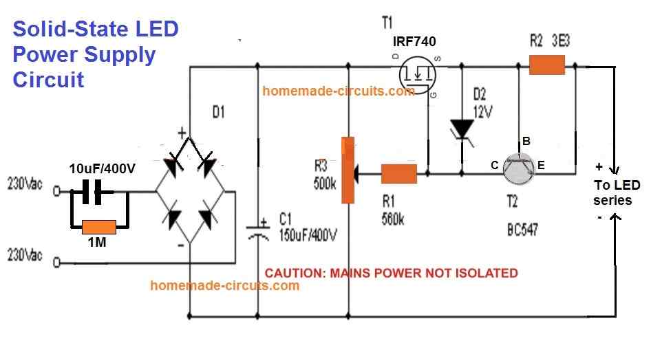
You just have to adjust the pot to set the output according to the total forward drop of the LED series string.
Meaning, if the total voltage of the LED series is say 3.3V x 50nos = 165V, then adjust the pot to get this output level and then connect it with the LED string.
This will instantly illuminate the LEDs at full brightness and with complete over voltage and over current or surge inrush current protections.
R2 can be calculated using the formula: 0.6 / Max LED current Limit
Improving the above Design
Although the above simple current controlled MOSFET LED driver looks easy and safe for illuminating high watt LEDs, it has one serious drawback.
The MOSFET can generate a lot of heat if the output is adjusted for low voltage LED strings.
The heat dissipation is basically due to the bridge rectifier and the C1 which converts the full AC cycle to DC, causing a lot of stress on the MOSFETs.
This aspect can be improved drastically by replacing the bridge rectifier with a single diode and moving the C1 capacitor parallel to the output LED, as shown in the following diagram:
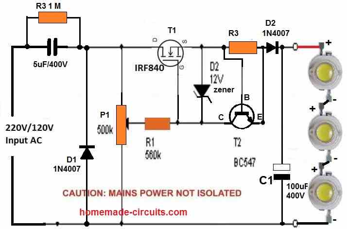
In the above diagram due to the presence a single diode D1 only half AC cycles are delivered across the MOSFET, causing 50% less stress and heat dissipation on the MOSFET.
However, the capacitor C1 parallel to the LED string ensures that the LED keeps getting the required power even during the absence of the other AC half cycles.
You can add more number of LEDs in series, a maximum upto 300 / 3.3 = 90 LEDs.
Make sure to adjust the P1 pot accordingly to adjust the output voltage to match the LED string's max forward voltage.
Likewise adjust the base/emitter resistor of T2 (BC547) to match the LED max current spec.
Using BJTs
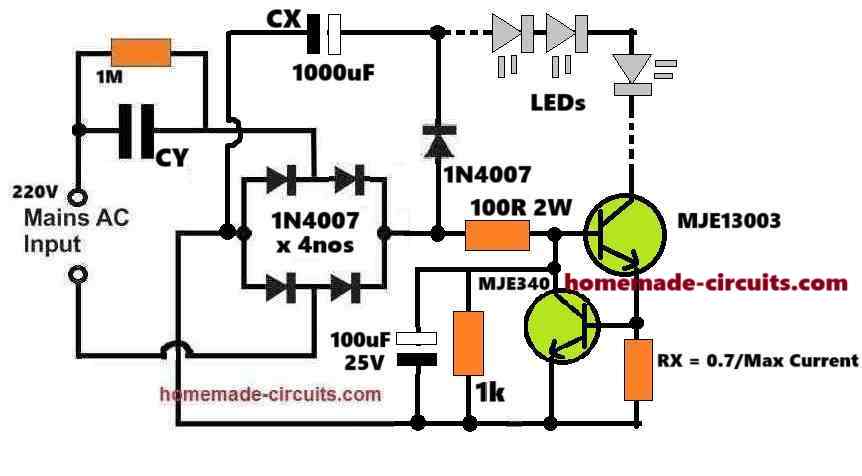
If you do not want to incorporate a MOSFET, then you can simply build the above design using BJTs as shown below:
How it Works
The main feature and operation of the design is controlling current and providing a safe constant current supply to the LEDs.
So we know, if the current is restricted then the LEDs can never burn regardless of the input supply voltage.
In this design, the capacitor CY does the main current limiting operation for the LEDs. Meaning, the reactance of the capacitor produces a resistance which limits the input 220V AC current to the maximum desired limit of the LEDs.
So, if the required maximum LED current is 300 mA, then you can select and adjust the value of the CY to ensure that it never allows the input current to exceed the 300 mA.
But if the CY capacitor itself can control the current for the LEDs, then why do we need the BJT current control stage, won't it be redundant?
The BJT current controller is necessary because the input AC 220V or 120V is never constant. If the input supply rises then CY will also start passing proportionally higher amounts of current to the LEDs, eventually causing damage to the LEDs.
The BJT current controller stage makes sure that even if the input AC supply happens to increase, it limits the excess current and ensures a constant current for the LEDs consistently and safely.
Moreover this BJT current controller stage also controls the switch ON in rush current making sure the LEDs are never subjected to any form of dangerous current inputs from the AC mains.
Calculating the Part Values:
Provided Data:
Input Voltage: 220V AC
LED Configuration: Let' us assume, 50 LEDs are in series
- Forward voltage per LED(VF) = 3.3V
- Total forward voltage VLEDs = 50 * 3.3=165V
LED Current Requirement: 300 mA (0.3A)
Capacitor CX: Acts as a filter for rectified DC voltage
CY: Limits the AC current to 300 mA
Transistors (MJE13003 and MJE340): Used as current regulators
Resistor RX: Used to calculate current regulation
Step 1: Capacitor CY for Current Limiting
The current through CY depends on its capacitive reactance XCX and the input AC voltage.
The formula is:
ICY = VAC / XC
Where:
XC = 1 / (2 * π * f * C)
For 50Hz mains frequency:
CCY = ICY / (2 * π * f * VAC)
Substitute:
CCY = 0.3 / (2 * π * 50 * 220)
CCY = 4.33 µF
Select CY = 4.7 µF (400V AC-rated).
Step 2: Resistor RX for Current Regulation
The resistor RX determines the current through the BJTs. The formula is:
RX = VBE / ILED
Where:
- VBE is the base-emitter voltage drop of the BJTs, typically 0.7V.
Substitute:
RX = 0.7 / 0.3
RX = 2.33 Ω
Select RX = 2.2Ω (5W-rated for safety).
Step 3: Filter Capacitor CX
The filter capacitor CX smooths the rectified DC voltage. Its value depends on the LED current and ripple voltage. Use the formula:
CX = ILED / (2 * π * f * Vripple)
Assume Vripple = 5V:
CX = 0.3 / (2 * π * 50 * 5)
CX = 191 µF
The voltage rating of CX must be higher than the total forward voltage of the LEDs, which is 165V.
Select CX = 191 µF (200V-rated). 1000uF is not required as shown in the diagram.
Step 4: Calculating the MJE13003 Base Resistor (100 Ω is wrongly shown in the diagram)
Collector Current (IC): 300 mA (LED current).
Current Gain (hFE) of MJE13003:
Typical hFE for the MJE13003 is around 8 to 10 at IC = 0.3A. Let’s use hFE = 10 as a conservative value.
Base Current (IB) Requirement:
The base current is given by:
IB = IC / hFE
Substituting:
IB = 0.3 / 10 = 0.03 A (30 mA)
Base-Emitter Voltage (VBE):
The base-emitter drop for MJE13003 is typically 0.7V.
Available Base Drive Voltage:
We will assume that the circuit supplies 165V rectified DC (across the LEDs and CX), because of the current limiting the 310V DC peak voltage from the 220V AC RMS will be forced to drop to the level of the LED total forward drop value. So, let us assume a standard voltage available at the base resistor is 165V.
Base Resistor Value (RB)
The base resistor limits the base current. Using Ohm's law:
RB = (Vbase - VBE) / IB
Where:
- Vbase = 165 V
- VBE = 0.7 V
- IB = 30 mA
Substituting:
RB = (165 - 0.7) / 0.03
RB = 164.3 / 0.03 = 5476.67 Ω
Power Rating of Resistor
The power dissipated by the resistor is:
PR = IB2 * RB
Substituting:
PR = (0.03)2 * 5476.67
PR = 0.09 * 5476.67 = 492.9 mW
Select a resistor with a slightly higher power rating for safety.
Resistor Value: Closest standard value = 5.6 kΩ.
Power Rating: 1W or higher (to handle power dissipation safely).
Step 5: Voltage Ratings of Components
Diodes (1N4007):
- Voltage rating: 1000V
- Current rating: 1A (sufficient for 300 mA)
Transistors:
- MJE13003: Suitable for high voltage switching
- MJE340: Handles low-side switching
LED Voltage Drop:
- Total forward voltage: 165V
- Ensure capacitor CX and diodes can handle this voltage
Finalized Component Values:
- CY = 4.7 µF (400V AC-rated)
- CX = 191 µF (200V-rated)
- RX = 2.2Ω (5W-rated)
- MJE13003 Base Resistor = 5.6 k (100 Ω is wrongly shown in the diagram)
- 1N4007 diodes: 4 pieces for rectification
- MJE13003: High-voltage transistor
- MJE340: Low-side current regulator
LED Bulb with Many Series LEDs
The next circuit of a LED bulb explained below is easy to build and the circuit is fairly reliable and long lasting.
The reasonably smart surge protection feature included in the circuit ensures an ideal shielding of the unit from all electrical power ON surges.
How the Circuit Functions
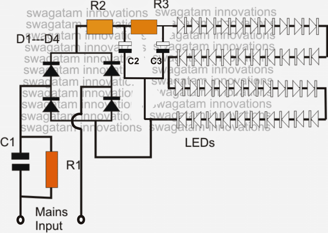
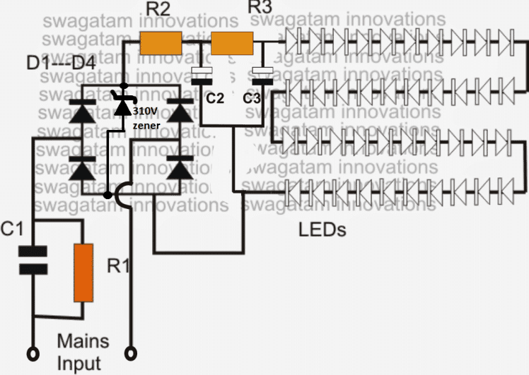
- The diagram shows a single long series of LEDs connected one behind the other to form a long LED chain.
- To be precise we see that basically 40 LEDs have been used which are connected in series. Actually for a 220V input, you could probably invorporate around 90 LEDs in series, and for 120V input around 45 would suffice.
- These figures are obtained by dividing the rectified 310V DC (from 220V AC) by the forward voltage of the LED.
- Therefore, 310/3.3 = 93 numbers, and for 120V inputs it's calculated as 150/3.3 = 45 numbers. Remember as we go on reducing the number of LEDs below these figures, the risk of switch ON surge increases proportionately, and vice versa.
- The power supply circuit used for powering this array is derived from a high voltage capacitor, whose reactance value is optimized for stepping down the high current input to a lower current suitable for the circuit.
- The two resistors and a capacitor at the at the positive supply are positioned for suppressing the initial power ON surge and other fluctuations during voltage fluctuations. In fact the real surge correction is done by C2 introduced after the bridge (in between R2 and R3).
- All instantaneous voltage surges are effectively sunk by this capacitor, providing a clean and safe voltage to the integrated LEDs at the next stage of the circuit.
CAUTION: THE CIRCUIT SHOWN BELOW IS NOT ISOLATED FROM THE AC MAINS, THEREFORE IS EXTREMELY DANGEROUS TO TOUCH IN POWERED POSITION.
Circuit Diagram#1
Parts List
- R1 = 1M 1/4 watt
- R2, R3 = 100 Ohms 1watt,
- C1 = 474/400V or 0.5uF/400V PPC
- C2, C3 = 4.7uF/250V
- D1---D4 = 1N4007
- All LEDs = white 5mm straw-hat type input = 220/120V mains...
The above design lacks a genuine surge protection feature and therefore could be severely prone to damage in the long run....in order to safeguard and guarantee the design against all sorts of surge and transients
The LEDs in the above discussed LED lamp circuit can be also protected and their life increased by adding a zener diode across the supply lines as shown in the following image.
The zener value shown is 310V/2 watt, and is suitable if the LED light includes around 93 to 96V LEDs. For other lower number of LED strings, simply reduce the zener value as per the total forward voltage calculation of the LED string.
For example if a 50 LED string is used, multiply 50 with the forward drop of each LED that is 3.3 V which gives 50 x 3.3 = 165V, therefore a 170V zener will keep the LED well protected from any sort of voltage surge or fluctuations....and so on
Video clip showing an LED circuit circuit using 108 numbers of LED (two 54 LED series strings connected in parallel)
90 LED Bulb Transformerless, using Capacitor Power Supply
Warning: This circuit is not isolated from mains, so be extremely careful while testing it in switched ON position, to avoid a fatal electric shock. The whole assembly must be housed inside a sturdy plastic container for proper safety. BUILD IT ONLY IF YOU FULLY AWARE OF THE DANGERS OF ELECTRIC SHOCK AND KNOW HOW TO TAKE THE NECESSARY PRECAUTIONS AGAINST IT.
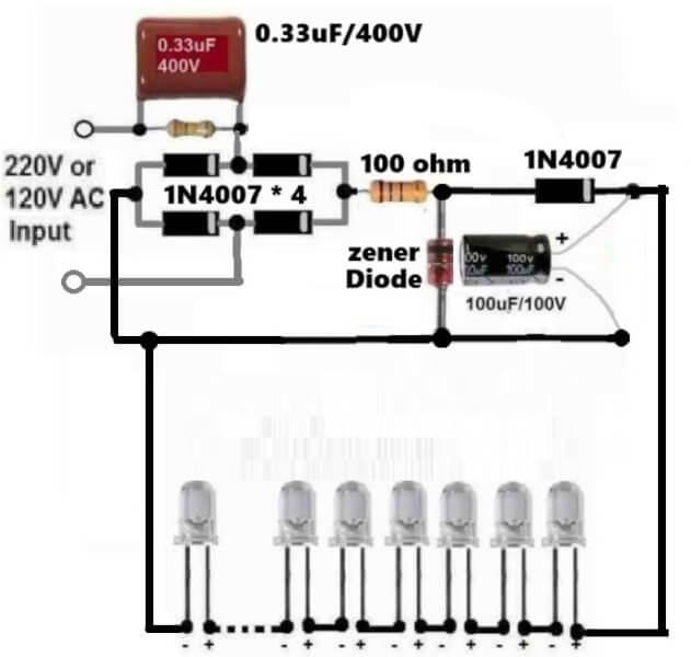
An LED bulb circuit can be a very intriguing project to build for any beginner or a school student, since this homemade project can be so useful and could be used for illuminating homes during night.
Although, the commercial LED bulbs are more sophisticated and employ an SMPS circuit, nevertheless the below shown LED bulb circuit could be built using capacitive power supply which is also equally efficient.
Note that the circuit can be customized as desired and any number of LEDs can be connected depending on the input AC supply level. For 220V, the number of LEDs can be up to 90 LEDs, and for 120V AC input the LEDs can be up to 45 nos.
The zener diode value will be equal to the value of the total forward voltage drop of the LEDs. For example if 90 LEDs are used then.
Total FWD drop = 90 x 3.3 = 297V.
So the zener diode value can be rated at 300 V.
Remember that the filter electrolytic filter capacitor value must be at least 25V higher than the zener value, if higher values than this is used, that will be fine.
High Watt LED Bulb using 1 watt LEDs and Capacitor
A simple high power LED bulb can be built using 3 or 4nos 1 watt LEDs in series, although the LEDs would be operated only at their 30% capacity, still the illumination will be amazingly high compared to the ordinary 20mA/5mm LEDs as shown below.
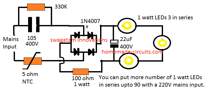
Moreover you won't require a heatsink for the LEDs since these are being operated at only 30% of their actual capacity.
Likewise, by joining 90nos of 1 watt LEDs in the above design you could achieve a 25 watt high bright, highly efficient bulb.
You may think that getting 25 watt from 90 LEDs is "inefficient", but actually it is not.
Because these 90nos of 1 watt LEDs would be running at 70% less current, and therefore at zero stress level, which would allow them to last almost forever.
Next, these would be comfortably working without a heatsink, so the entire design could be configured into a much compact unit.
No heatsink also means minimum effort and time consumed for the construction. So all these benefits ultimately makes this 25 watt LED more efficient and cost effective than the traditional approach.
Circuit Diagram#2
Surge Controlled Voltage Regulation
If you require an improved or a confirmed surge control and voltage regulation for the LED bulb, then the following shunt regulator could be applied with the above 3 watt LED design:
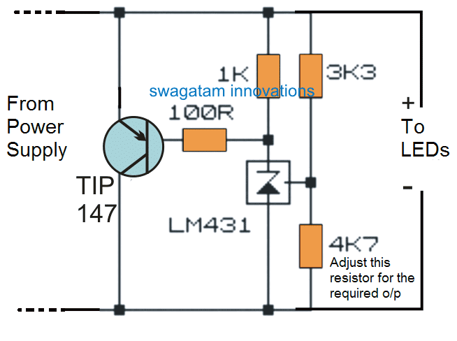
Video Clip:
In the videos above I have purposely flickered the LEDs by twitching the supply wire just to test ensure that the circuit is 100% surge proof.
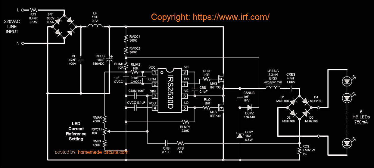
Solid State LED Bulb Circuit with Dimmer Control using IC IRS2530D
A simple yet efficient mains transformerless solid state LED controller circuit is explained here using a single full bridge driver IC IRS2530D.
Highly Recommended for you: Simple Highly Reliable Non-Isolated LED Driver - Don't Miss this, Fully Tested
Introduction
Normally LED control circuits are based on buck boost or flyback principles, where the circuit is configured to produce a constant DC for illuminating an LED series.
The above LED control systems have their respective drawbacks and the positives in which the range of operating voltage and the number of LEDs at the output decide the efficiency of the circuit.
Other factors like whether the LEDs are included in parallel or series or whether they need to bedimmed or not, also affects the above typologies.
These considerations make these LED control circuits rather dicey and complicated.The circuit explained here employs a different approach and relies on a resonant mode of application.
Though the circuit does not provide direct isolation from the input AC, it has the features of driving many LEDs with current levels as high as 750 mA. The soft switching process involved in the circuit ensures greater efficiency to the unit.
How the LED Controller Functions
Basically the mains transformerless LED control circuit is designed around the fluorescent lamp dimmer control IC IRS2530D. The circuit diagram shows how the IC has been wired up and how its output has been modified for controlling LEDs in place of the usual fluorescent lamp.
The usual preheating stage required for a tube light utilized a resonant tank which is now effectively replaced by a LC circuit suitable for driving LEDs.Because the current at the output is an AC, the need of a bridge rectifier at the output became imperative; this makes sure that current is continuously passing through the LEDs during every switching cycle of the frequency.
The AC current sensing is done by the resistor RCS, placed across the common and the bottom of the rectifier.This provides an instant AC measurement of the amplitude of the rectified LED current.The DIM pin of the IC receives the above AC measurement via the resistor RFB and capacitor CFB.
This allows the dimmer control loop of the IC to keep track of the LED current amplitude and regulates it by instantaneously varying the frequency of the half bridge switching circuit, such that the voltage across the LED maintains a correct RMS value.
The dimmer loop also helps to keep the LED current constant irrespective of the line voltage, load current and temperature changes.Whether a single LED is connected or a group in series, the LED parameters is always maintained correctly by the IC.
Alternatively the configuration may also be used as a high current transformerless power supply circuit.
Circuit Diagram#3
Original article can be found here
Why use LEDs
- LEDs are being Incorporated in vast magnitudes today for everything that may involve lights and illuminations.
- White LEDs have especially become very popular due to their mini size, dramatic illuminating capabilities and high efficiency with power consumptions. In one of my earlier post I discussed how to make a super simple LED tube light circuit, here the concept is quite similar but the product is a bit different with its specs.
- Here we are discussing the making of a simple LED bulb CIRCUIT DIAGRAM, By the word "bulb" we mean the shape of the unit and the fitting secs will be similar to that of an ordinary incandescent bulb, but actually the whole body of the "bulb" would involve discrete LEDs fitted in rows over a cylindrical housing.
- The cylindrical housing ensures proper and equal distribution of the generated illumination across the entire 360 degrees so that the entire premise is equally illuminated. The image below explains how the LEDs needs to be installed over the proposed housing.



Questions & Answers
Dear Jash,
No, this circuit will not be able to drive 1 watt LEDs.
hello shail,
the above circuit will work for both the voltages, however 120V won't support more than 32 LEDs.
A capacitive power supply cannot be modified for producing 2 amp current, it can be dangerous and is not recommended.
Good afternoon swagatam.
My name is kelvin, my passion to design an LED lighting system is very intense but i don't have the complete knowledge yet, that is why i decided to access the internet to acquire more knowledge, in search i found your blog, with what i saw i was amase and as well happy because i know i can get some aid from you.
From the prototype above 3-LED was connected in series with a resistor.
My question is if my main is 220V how can i know the value of resistor to use in series with the 3-LED?
Hi Kelvin, thanks!
You can use the following formula:
Supply voltage – LED fwd voltage divided by LED current
With a capacitive power supply, after rectification the output would be 330V, 3 LED would have 3.3×3 = 9.9V as the FWD voltage and with 5mm LEDs the current for the series would be 20mA or 0.02 A,
Therefore 330 – 10/.02 = 16000 ohms or 16k is the resistor required.
But practically any smaller value resistance works with the above type of circuit because the current input from the capacitor is too low and therefore has little strength to burn anything.
Thanks for the reply.
The circuit i am talking about is the one constructed by Mr.Ishaan Pathania your follower.
How can i get the value of the resistor he used?
The prototype used a 12V supply, the formula mentioned above is standard for all supply voltages, and may be used for the prototype also.
Thanks for your reply sir.
What i am asking is, how will i know the values of the resistors to use in series with the 3-leds connected in series in the circuit constructed by Mr.Ishaan Pathania if i am to construct the same circuit?
Thanks for your reply sir.
Q1. If my supply voltage is 220v, does this means that the FWD voltage for 1LED is 2.2v?
Q2. How can i get the LED current?
FWD voltage and current are fixed parameters as per the particular LED specifications, check out their datasheets for it.
For example a 5mm LED normally has 3.3V as the FWD voltage and 20mA as the operating current.
Thanks for your reply sir.
HI! Mr.Swagatam i built your awesome circuit and it was working fine! After a couple of months it started to flicker. Now after 2 days of flicking it's stopped working. Could you tell me why this could have happened, could it be that one of the caps has gone bad?
Thanks!!
Hi Dilandki, this problem is the main issue with these kinds of circuits, it happens due to occasional surge currents, you can either use a thermister at the input for cancelling these surges or use an SCR network as shown in this post:
https://www.homemade-circuits.com/2013/05/variable-surge-free-high-current.html
for thermister connection see this circuit:
https://www.homemade-circuits.com/2013/02/using-ntc-resistor-as-surge-suppressor.html
OK I'll do that, thanks for the advice.
One more thing Mr Swagatam, I made another one of these circuits, and when I checked the output voltage my multimeter reads 27 volts is that correct? or is something wrong with my circuit?
And on another occasion i built your circuit it worked fine for a couple of days, but then it stopped working. My bulb has 35 led's in series, I checked the led's, all of them were fine. Then i started to power the leds 5 at a time, and they DID light up. When i reached 20 the leds were dim, and above 20 led's none of them would light up. This is strange cause all 35 led's were working 2 days ago(very bright too), and now the circuit doesn't have enough juice to power all of them. Could you tell me why this happened??
THANKS IN ADVANCE!
Without load it should read equal to the bridge capacitor value, therefore the bridge capacitor should be rated at the highest possible value. lower values will slowy damage and leak the capacitor.
for 35 LEDs, the output should be 35×3 = around 100V, I tink either one of the capacitors may be faulty in the circuit.
Oh another thing Mr. Swagatam if i were to power 12, 1watt LED's in series(with maximum brightness, what changes do i need to do to your circuit?
capacitive power supplies are well suited for low current high voltage type devices, 1 watt LEDs do not come under this category and therefore will not work efficiently with the above circuit.
so if i changed the main 474k 400v cap to 3 uf, and the 1 uf cap to 100uf will i be able to drive 12+ 1watt led's in series with maximum brightness?
Unless you make the forward of the LEDs equal to the output voltage of the capacitor, it won't work.
you will have to connect at least 60/70 LEDs in series only then you might be able to reach full illumination.
ohh i see….. so do you have an awesome circuit to drive 1 watt power LED's? I searched your site but i couldn't find it anywhere. It would be a real help if you could post a circuit for 1 watt led's.
Thanks in advance!!
I have something in my mind regarding this, will share it soon in my blog.
hello
Hello sir,
Sir i want to drive 160 led can i use 32 -32 led's group in parallel with this circuit.plz help me out
hello Kapil,
yes you can do that!
Hello sir, i want to launch LED Bulbs in the market at low cost and also want to provide 1 year guarrenty with it.
So, is this circuit suitable for this?
Hello Deepak,
I am not quite sure about the life of this circuit, however by putting a 200V/3w zener diode parallel to C2 can make the circuit much reliable.
you can take the help of the following post for making it:
https://www.homemade-circuits.com/2013/06/universal-high-watt-led-current-limiter.html
Tanks Mr. Swagatam, I've done with this circuit. My Question is what kind of LEDs to make a real bulb, I mean not corn bulb, so we need less LEDs (3-10) & can I appy this circuit to do that? #reallysorry'boutmyBadEnglish
Hey Swagatam,
is there any substitute for 200V, 1watt Zener Diode???
plz tell me
Hi Bharat,
You can try this circuit, remove D1 and use it for setting any desired surge free output voltage
https://www.homemade-circuits.com/2013/02/how-to-make-simple-220v-transformerless.html
yes SMD leds will also work here.
Sir, Can i use 250v MOV in parallel in front of input voltage in this circuit for high volt protection……
PLZ Suggest me….
Yes, you can use it, put it after C1
Sir,
Do you have any circuit which provide 12v 100ma power supply………
Avik, you can try the following design:
https://www.homemade-circuits.com/2012/08/high-current-transformerless-power.html
dimension the input cap for 100ma output
Hello sir…..
can i put 10 strings of 4 leds in parallel??
What could be change in the circuit?
Good afternoon friends.
My name is john, my passion to design an LED star lighting system is very intense but i don't have the complete knowledge yet, that is why i decided to access the internet to acquire more knowledge, in search i found your blog, with what i saw i was amase and as well happy because i know i can get some aid from you.
My question is if my main is 220V , i want working 45-50 LED, i dont know value of resistor and capacitor . if you dont mind plz tell the electricity diagram
can i know the value of resistor to use in series with the 3-LED?
Hi John, if you want to use a capacitive power supply as explained above, then probably the calculations won't be too critical, still you can refer to the following article for details:
https://www.homemade-circuits.com/2011/12/how-to-calculate-and-deduce-current-and.html
with 3 leds the formula for the resistance would be
R = supply V minus total led forward V divided by LED current
i am sorry i dont understand
My question is if my main is 220V , i want working 45-50 LED, i dont know value of resistor and capacitor . if you dont mind plz tell the electricity diagram
my main 220v, i have 1watt LED 45ps, how i can work this LED's 220v ???
you did not mention in your first comment regarding 1 watt LEDs…for 1 watt leds,45 nos you will need a 12V 5amp smps power supply and connect with it 15 parallel strings of these leds each having 3 leds and a separate 6ohm 1 wat resistor
hi …swagatam
i dont have smps power supply…i dont want use smps power supply…i have 1n4007 4ps,474/400v 1ps, 10uF/400v 1ps….how connect
Hello sir……
Can i put 4 strings of. 10 led in parallel???
What could be change in the circuit?
Helo sk,
Parallel srings will result in low illumination, so it's not recommended, you should connect all the LEDs in series only.
sir i need to connect only 10 to 20 leds what changes should be needed?
You can use the same circuit which is shown above.
Please suggest the exact value of NTC which we can use for Surge Suppressor for the circuit
https://www.homemade-circuits.com/2012/04/how-to-make-led-bulb-circuit.html
And please also mention if the require NTC value is 5d-11 for
https://www.homemade-circuits.com/2013/02/using-ntc-resistor-as-surge-suppressor.html
And if time allow please elaborate in Surge protection circuit which we can design from component available in market. I read your topic on surge protection but exact value are not mention ( like for MOV ) so it difficult for beginners …. Facing very difficulties due to voltage fluctuation in my village town. many led bulb are stopped working. so kindly please reply. looking forward to hearing from you …..
posted on your fb wall too, plz reply,, really needed your help
There's a big range of NTCs and MOVs ithe list and it's difficult to suggest a particular value because they are so closely differentiated, so it would be better to consult with your local electronic dealer regarding the correct one.
If you want to avoid an NTC, you can use a transformer power supply in place of capacitive power supply and use a 7812 or 7824 IC for getting a well regulated power supply.
Hello swagatam.
Could you help me with the values of r1,r2,r3. The values and types of ci and c2, the values for d1,d2,d3,d4 for 110v ac. i am using the same 40 leds 3.2 v 30ma thank you in advance.
Ps congrats you have the best circuit in the net
Hello Lus,
You can use the same circuit which is given above for your application also, nothing needs to be changed except may be R2/R3 which can be reduced to 50 Ohms each.