Obstruction lights are warning lights that we see at the top of tall structures like towers and skyscrapers, installed for indicating the aircrafts and other flying objects about these obstructions.
These lights alert the flying aircrafts regarding the minimum height they should maintain above these tall structures to avoid a possible collision and accidents.
Obstruction lights are mostly red in color so that they can be visualized from maximum distance and even during foggy conditions. These can be a continuously illuminated type of lamp or a flashing, revolving beacon type of lamp.
In this this article I have explained about an easy construction of a powerful LED based obstruction light system, using minimum parts, and efficient working.
The idea was requested by Mr. Jerry as given below:
Circuit Specifications
I have a medium intensity obstruction light that has gone faulty. It’s input voltage is 48 VDC and it’s power is 60 W. It has four circuits that has 12 LEDs per circuit. It also has an LDR which is supposed to switch the light off during the day time and ON during the night.
Now because of the damaged components which I couldn't find their ideal numbers, I want you to design another circuit for me that will be able to perform the same function as before, remember that it flashes (it goes on and off) flip flop. The four different circuits have their supply from the 48VDC.
The four circuits I guess work in two ways: The upper part and the lower part. Two circuits controls the upper part while the other two controls the down part.
The flash should be about 2 sec interval (on and off) that should be continuous, it has a photocell also.
Design a circuit that will be able to control the upper and lower parts of the system at the same time and make a provision should there be need to separate the upper part from the lower part. The power is 60W/48VDC.
Circuit Analysis
Analyzing the above description we are able to conclude the following assumptions.
It seems the 4 circuits are 4 separate but identical LED drivers, employed for controlling current for the 4 LED groups separately. The separate drivers ensure that all LEDs together can never fail in case of a malfunction.
The 60 watt power is for all the LEDs combined, therefore each 12 LED group should be rated at 5 watts. In other words the current through each 12 LED string can be 0.12 amps, or 120 mA.
The inclusion of an LDR and also a photocell appear confusing, so we'll ignore the photocell and use only an LDR for the required automatic day night switching.
Circuit Design
As explained above, the 4 circuits can be 4 LED drivers, or to be precise current controller circuits for safeguarding the LEDs from over current.
However, a deeper analysis shows that a 120 mA LEDs may not require a special current controller, and a resistive current limiting may be quite sufficient. We consider the input supply 48V DC to be relatively constant.
The LED that we can select for this obstruction light circuit project are 2835 SMD LEDs for optimum brightness. The technical details can be studied from the from data:
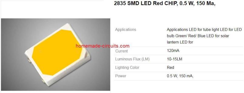
2835 SMD LED Specifications
Calculating Current Limiting Resistor
The current limiting resistor for each of the series 12 LED group can be calculated from the following formula:
R = Vs - Total FWD Drop / Limiting Current
- where Vs is the supply voltage = 48 V
- Total Fwd drop = 12 x 3.1 = 37.2
- Limiting current: 0.12 amperes
Therefore,
R = 48 - 37.2 / 0.12 = 90 Ohm
Wattage of the resistors will be (48 - 37.2) x 0.12 = 1.2 watts or 1.5 watts rounded of.
Using a Transistor Astable for Flashing the LEDs
Since the obstruction light LEDs need to be blinked in a flip flop mode, a transistorized astable circuit appears to be a good choice. This is because a transistor based astable offers two alternately oscillating transistor outputs which could be used for blinking two sets of LEDs separately.
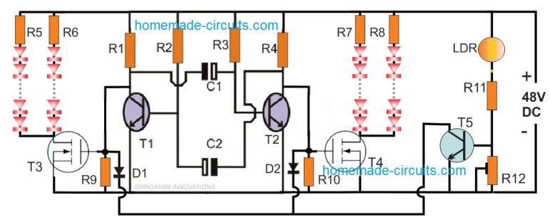
Complete Circuit Diagram can be seen below:
Parts
- R1, R4 = 22 k Ω
- R2, R3 = 78 k Ω
- R9, R10, R11 = 6k8
- R12 = 100 k preset
- R5, R6, R7, R8 = 90 Ohms 1.5 watt
- C1, C2 = 1 μF/60 V
- T1, T2, T5 = BC547
- T3, T4 = IRFD110
- D1, D2 = 1N4148
- LDR, photoresistor = typically, 30 k in day light under shade
- LEDs = As discussed above, 48 nos.
How it Works
The proposed LED obstruction light circuit working can be understood with the following point:
The 4 resistors at the center, along with C1, C2 and T1, T2 form a basic transistorized astable multivibrator circuit. The main feature of this astable is its low cost, and quick failproof functioning as soon as it's powered. Once switched ON, T1 and T2 alternately begin switching at a frequency rate determined by the base resistors R2, R3, and the capacitors C1, C2.
These specific components can be changed as desired for altering the switching rate of the T1 and T2. Higher values will produce slower switching rates and vice versa.
Another advantage of this astable is that it can be dimensioned to operate at higher voltages, such as 48 V here, without incorporating special voltages regulator stages. Furthermore, we are able to achieve a two alternately switching outputs, which may not be possible with IC based astables, unless an external BJT is applied.
The MOSFETs T3, T4 are used for switching the LEDs in accordance with the blinking signals from the respective astable BJT collectors.
The LEDs are divided into 2 groups of 24 LEDs each, which can be configured on top and bottom of the obstruction light cabinet. These groups of the LEDs then go on flashing flip flop continuously as long as they are powered.
The T5 stage is the day night automatic switcher circuit. When sufficient light is available during day time, T5 gets biased through the LDR low resistance, and keeps the two MOSFETs switched OFF by grounding their gates.
As darkness falls, the LDR resistance increases, which gradually depletes the base bias from T5, ultimately switching it OFF.
When this happens, the MOSFETs become enabled and they begin switching the LEDs alternately, quickly serving the intended function of an obstruction lamp.
During day time the maximum consumption of the circuit is not more than 5 mA.


Questions & Answers
This is a great article to read. I have an obstruction light project where I need to flash 4 strings of 10 each LED in series using 4 parallel drivers. Each string of LED”s need to flash at the same time. I need to power them with 90-277 VAC input with an output of 350mA to each LED. The LED are Osram SSL150 Red LED. Can you help
Glad you liked the article. you can try the TRIAC based circuit shown in the following article:
https://www.homemade-circuits.com/how-to-make-any-light-strobe-light/
Replace L1 with the parallel LEDs and their respective drivers.
Hello Sir! Good Day! I would like to ask for your help in this scenario: “You are working in a Cell Site Construction Project and you are assigned in the design and installation of the Tower Light. The height of the tower makes it unfeasible to install DC Powered Tower lights due to loss of power in the transmission line. There is no control circuit inside the tower light to make it blink. For this Cell Site, the tower light is required to turn on for 2 seconds and turn off for 2 seconds.”
I hope you can help me sir in creating and designing a circuit design of tower light. Thank you so much!
Hello Kazune, you can use the circuit which is explained in the above article, and power it from a small windmill system.
Hi,
As per your suggestion, i have eliminated D2, R10, T4.
I have put all the four strings of LEDs along with R7 & R8 in parallel on Drain of T3.
I need to make the flashing rate of LEds changeble, for 10 to 60 flashes per minute.
Also please suggest how to adjust LDR for darkeness response by preset
Please guide.
Thanks
hello Vikram Jatania. Once I solved the problem-preset of photo-switch, by steps:
1-to take another one “LDR”=photoresistor EXACTLY like in the circuit or remove LDR for measurement =there is a risk of damage at demount-mount works e.g.=better to take another one. If you know the LDR’s “name”-you can open LDR’s datasheet for waste steps2-4.
2-put the LDR to a dark box with connected leads of a resistance measure. Founded dark resistance necessary.
3-to light the fotoresistor by a “flashlight” with adjustable intensity of light and by a direct sun with recorded resistance at all of all these intensities of light, measured visually by your look or by a light-meter or other. Good – 3-10 points of a different light brightness to LDR under measurements-between full dark and full=direct sunlight.
4-to draw curve resistance-light intensity and store the curve until end of the circuit use. Find out necessary resistance of LDR (Ohms) according to desired on-off spot-lighters/other loads threshold.
5-in your practical circuit – to change LDR onto a “simple resistor” with resistance as founded step.4 via curve- for test and set circuit’s work. Mean the-to find out R11 and R12 resistances for correct threshold at your supply voltage from highest to lowest to the photo relay work. Also Is possible 100% nontransparent cover upon LDR with a “simple resistor” paralleled to LDR until all done. Than cover and “simple resistor”removed.
Hi, you can replace R2 and R3 with 100k pots, and make sure to connect 10k resistors in series with each of these pots. R12 is already given for adjusting the LDR response
Hi,
Thanks for responding promptly. I understood you suggestion. “You can simply do it by adding all the 48 LEDs across one of the MOSFET drains, and eliminating the other side MOSFeT stage completely”.
But it will be very helpful if you could show me the revised circuit diagram.
Thanks and regards.
It is actually very easy, you just have to remove D2, R10, T4, R7, R8, and the associated LEDs, and put all the 48 LEDs on the drain side of T3
Can you modify the circuit so that all the 48 LEDs that is, all the12 X 4 parallel strings Blink at the same time instead of Flip Flop.
Also it would be great if you can share circuit diagram for 230VAC to 48VDC power supply. Thanks.
You can simply do it by adding all the 48 LEDs across one of the MOSFET drains, and eliminating the other side MOSFeT stage completely.
You can use the 4rth circuit idea from the following link, for the power supply:
Transformerless Constant Current 1 watt LED Driver Circuit
Alright sir, but with the 12vdc supply, will the IC 555 be able to handle that amount of LEDs ie..up to 50 in number or more? If yes please let me see the circuit. Thanks.
No, 555 cannot handle 240 mA
Hello sir,
I want to know if a single 555 IC can control 50 LEDs in a flip flop without damaging the the IC. If I have an input voltage of 48vdc, give a design that will still use the 555 IC. And can 555ICs be used in parallel or any other IC?
Hello Jerry, if 20mA LEDs are used even then 50 LEDs would consume 240 mA at 12 V which is way beyond the range of a IC 555 current specs. IC 555 cannot be used in parallel, and it will work with 12 V only, not with 48 V