• Skip to main content
  • Skip to primary sidebar

Homemade Circuit Projects

Need circuit help? Post them in the comments! I've answered over 50,000!

Blog | Categories | About | Hire Me | Contact | Calculators-online
You are here: Home / IC SG3525, SG3524 Calculator

IC SG3525, SG3524 Calculator

Now let us check this calculator for the SG3525 IC. Here this calculator will estimate the oscillator frequency based on the timing components as given below:

  • Rt = timing resistor (Ohms)
  • Ct = timing capacitor (Farads or µF)
  • Dead Time (optional)
Calculator by homemade-circuits.com

SG3525 Frequency Calculator
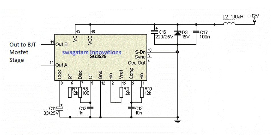


simple SG3525 inverter

SG3525 Oscillator Frequency Formula:

f = 1 / ( (0.7 * Rt + 3 * Rd) * Ct )

If you are not using a dead-time resistor (Rd) then simplified formula is:

f = 1 / ( 0.7 * Rt * Ct )

In the above calculator the user can:

  • Enter Rt in kΩ
  • Enter Ct in nF
  • (Optional) Enter Rd in kΩ if needed

Example:

RtCtRdFrequency
10 kΩ1 nF(none)≈ 142.85 kHz
10 kΩ10 nF(none)≈ 14.28 kHz
10 kΩ1 nF2.2 kΩ≈ 92.17 kHz

SG3525 Duty Cycle Calculator

SG3525 Duty Cycle Calculator


PWM Pulse Width Calculator

SG3525 PWM Pulse Width Calculator


Transformer Turns Calculator (For Full Bridge or Push-Pull)

Assuming the turns and voltage ratio formula is:

Vp / Vs = Np / Ns

Transformer Turns Calculator


Reader Interactions

Comments

  1. Camilo Astillo says

    October 19, 2026 at 10:22 am

    can you kindly show me a half bridge topology SMPS diagram with parts ID?
    I almost finished my diy SMPS project but I can’t even to oscillate it.
    it has a good square wave 30khz out on both GDT secondary coil but, when I connect it to the mosfets the SG3525A becomes hot and the gate source 60khz frequency changed. I don’t know what to do next.

    Reply
    • Swagatam says

      October 19, 2026 at 11:06 am

      I will surely try to solve the problem you are facing. Can you please tell me the exact specifications of your SMPS? Let me know I will try to figure it out.

      Reply
  2. Ngwabe David says

    August 22, 2026 at 6:30 pm

    how thanks for the advise .
    the resistor of 100 from pin 7 to groung is it suposed to beconected like that or it is a mistake i thought it is to pin 6

    Reply
    • Swagatam says

      August 22, 2026 at 9:02 pm

      the 100 Ω resistor shown from Pin 7 to ground is a mistake, it should be between Pin 7 to Pin 5 through a resistor, which decides the deadtime

      Reply
  3. Hillary says

    December 16, 2025 at 6:56 am

    hi, good morning. please how can I get a perfect ferrite core transformer winding for 30KHz, 12v inverter. I have been finding it difficult to do so

    Reply
    • Swagatam says

      December 16, 2025 at 8:38 am

      Good morning, you can try one of these articles to configure it:
      https://www.homemade-circuits.com/?s=smps+calculator

      Reply
  4. Segun says

    November 10, 2025 at 9:04 pm

    the frequency calculated for Sg3525, 100HZ for instance, is it for the two sides or one side of the oscillator alone?

    Reply
    • Swagatam says

      November 11, 2025 at 8:13 am

      It is for one side….which should be 50Hz/60Hz, not 100Hz.

      Reply
  5. HASAN HABEEB MADHI says

    November 4, 2025 at 8:57 pm

    hi I have SG3525 like to use I’n ignition coil circuit diagram I need to get CT&CR number

    Reply
    • Swagatam says

      November 5, 2025 at 7:50 am

      Hi, sorry, i did not understand what you meant by CT and CR numbers?

      Reply

Need Help? Please Leave a Comment! We value your input—Kindly keep it relevant to the above topic! Cancel reply

Your email address will not be published. Required fields are marked *

Primary Sidebar

My YouTube Channel

Circuit Simulator: Draw and Simulate Schematics

circuit simulator image

Categories

  • Arduino Projects (95)
  • Audio and Amplifier Projects (134)
  • Automation Projects (18)
  • Automobile Electronics (104)
  • Battery Charger Circuits (90)
  • Datasheets and Components (109)
  • Electronics Theory (151)
  • Energy from Magnets and Earth (43)
  • Games and Sports Projects (11)
  • Grid and 3-Phase (20)
  • Health related Projects (27)
  • Home Electrical Circuits (13)
  • Indicator Circuits (16)
  • Inverter Circuits (104)
  • Lamps and Lights (170)
  • Meters and Testers (72)
  • Mini Projects (28)
  • Motor Controller (68)
  • Oscillator Circuits (30)
  • Pets and Pests (15)
  • Power Supply Circuits (91)
  • Remote Control Circuits (50)
  • Security and Alarm (65)
  • Sensors and Detectors (107)
  • SMPS and Converters (46)
  • Solar Controller Circuits (62)
  • Temperature Controllers (44)
  • Timer and Delay Relay (51)
  • Voltage Control and Protection (44)
  • Water Controller (37)
  • Wireless Circuits (31)

Subscribe to get New Circuits in your Email

Other Links

  • Privacy Policy
  • Cookie Policy
  • Disclaimer
  • Copyright
  • Videos
  • Sitemap

People also Search

555 Circuits | 741 Circuits | LM324 Circuits | LM338 Circuits | 4017 Circuits | Ultrasonic Projects | SMPS Projects | Christmas Projects | MOSFETs | Radio Circuits | Laser Circuits | PIR Projects |

Recent Comments

  • Swagatam on IC SG3525, SG3524 Calculator
  • Swagatam on Long Duration Timer Circuit using IC 4541: Working and Calculations
  • Swagatam on 9 Simple Metal Detector Circuits Explained
  • Swagatam on 7 Easy Sawtooth Waveform Generator Circuits using UJT, IC 555, and Transistors
  • Camilo Astillo on IC SG3525, SG3524 Calculator

Social Profiles

  • Twitter
  • YouTube
  • Instagram
  • Pinterest
  • My Facebook-Page
  • Stack Exchange
  • Linkedin

Calculators

  • ZVS Induction Heater + Tank Calculator Tool
  • Zener Diode Calculator
  • Wire Current and Thickness Calculator (Ampacity Calculator)
  • Voltage Divider Calculator
  • Transistor Base Resistor Calculator
  • Transistor Astable Multivibrator Calculator
  • TL431 Calculator
  • Solar Panel, Inverter, Battery Calculator
  • Ferrite Core Air Gap Calculator Tool
  • Parallel MOSFET Calculator Tool: How to Connect MOSFETs in Parallel Safely
  • LC Resonance Calculator for EV Battery Charger Circuits
  • LED String Series Resistor Calculator
  • PFC (Power Factor Correction) Calculator Tool: 3kW
  • Passive Power Factor Correction (PFC) Calculator
  • LM567 IC Calculator Tool
  • SMPS Flyback Boost Converter Calculator
  • Shunt Resistor Calculator for Ammeters
  • SCR and Triac Gate Resistor Calculator
  • Battery Back up Time Calculator
  • Boost Converter Calculator (Non-Isolated)
  • Bootstrap Capacitor Calculator
  • Buck Converter Calculator
  • Buck-Boost Converter Calculator
  • Capacitance Reactance Calculator
  • DCM Flyback Transformer & Wire Gauge Wire Size Calculator Tool
  • Filter Capacitor Calculator
  • IC 4047 Calculator (Frequency and PWM)
  • IC 4060 Calculator
  • IC 555 Astable Calculator
  • IC 555 Monostable Calculator
  • IC SG3525, SG3524 Calculator
  • Inductance Calculator
  • Induction Heater Inductor and Resonant Frequency Calculator
  • Induction Heater Work Coil Calculator
  • Inverter LC Filter Calculator
  • LC Resonance Calculator
  • LED Current Calculator
  • LM317, LM338, LM396 Calculator
  • NAND/NOT Gate RC Values Calculator
  • NOT, NAND Gate Frequency Calculator
  • Notch Filter Calculator Tool
  • Ohm’s Law Calculator
  • Phase Angle Phase Shift Calculator
  • Power Factor (PF) Calculator
  • RC Filter Calculator
  • Reactance Calculator
  • Sine Table Calculator for SPWM Arduino Code
  • Small Signal Transistor(BJT) and Diode Quick Datasheet
  • SMPS Calculator for Toroidal Ferrite Transformers
  • SMPS Flyback Transformer Calculator – Design by Target Duty Cycle
  • TL431 Calculator
  • Op-Amp Hysteresis Resistor Calculator

© 2026 · Swagatam Innovations