The three watt amplifier circuit discussed in the earlier post could be effectively upgraded into a 30 to 40 watt transistorized amplifier circuit, simply by adding a 2N3055 power output stage. The entire procedure for this is explained in the following article.
The circuit was requested by Mr. Clifford. The requested specifications can be viewed in the following paragraph:
I would like to ask if you do have a proven working 20 or 40 watts stereo audio amplifier with its schematic diagram, parts list, PCB design and Parts placement guide?
The class has 3 projects to do all through out the term.
1. Power supply for the audio amplifier (12V, 6A may be it depends on the audio amplifier)2. The Audio Amplifier it self (20 or 40 watts stereo)
3. Simple tone control circuit. (active or passive)
I choose audio amplifier as their main project because working on a audio amplifier can give you allot of learning. Example they can learn the principle of diodes,filters, bridge circuits,regulators on the power supply circuit. Transistors, IC, RLC circuits on the audio amplifier..and some capacitor filters and voltage divider principles on the tone control circuits.
I would be very please if you have all of the three circuits for the power supply, audio amplifier and Tone control circuits with their Schematic diagram, parts list,PCB design, PPG Etc.
Of-course I will be first making all the 3 circuits for them to have a visual what would be the finish output of the class.
Thank you so much!
Circuit Diagram
How it Works
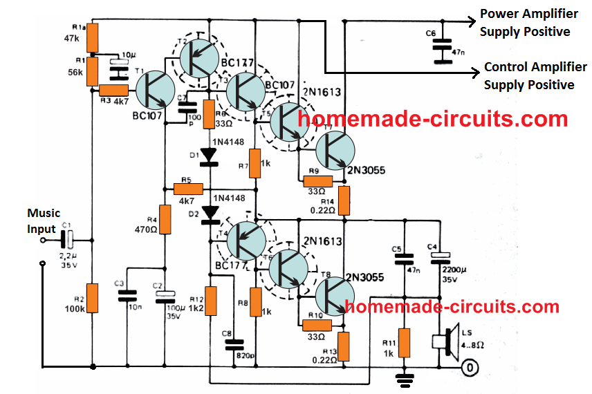
The working of the amplifier is basically the same as its smaller version, and can be understood with the help of the following points:
Capacitor C7 is used here to correct and adjust the phase shift happening due to the inclusion of the 2N3055 output transistors.
The value of R1 is lowered to 56 k, and an extra decoupling, by means of a 47 k resistor and a 10 µF capacitor, has been introduced between the high potential terminal of R1 and positive line. The output impedance is extremely low, since T5/T7 and T6/T8 are rigged as power Darlingtons BJTs.
The driver amplifier stage behind the 2N3055 stage is effectively equipped for delivering the essential 1 V RMS for driving the main amplifier. Due to the low input sensitivity, the amplifier offers excellent stability, and the sensitivity to hum pickup is minimal.
Large negative feedback through R4 and R5 guarantees reduced distortion.
The highest allowable supply voltage is 42 V. The power supply circuit is designed using a stabilized transistorized circuit to work with suitable higher voltages.
Besides the heatsinks indicated in the amplifier and power supply circuits, the 3 nos 2N3055 transistor temperature also needs to be controlled, and this may be accomplished by installing them on the amplifier metal enclosure itself, using mica insulating washers.
The shown power supply table has been calculated to suit a 30 watt stereo configuration.
Power for the control amplifier is acquired out from a 2N1613 transistor which has its base potential fixed at one half the primary supply voltage.
Power Output Specifications
The power output or the wattage specifications will depend on how the supply voltage and the loudspeaker are chosen for the design. The relevant output data for the different supply voltages, and loudspeaker parameters are as described below:
With 30 V supply, the output will be around 10 watts and 20 watts for 8 Ohm speaker and 4 Ohm speaker respectively. For 2 Ohm speaker the output will be around 35 watts (R13 and R14 will be 0.1 Ohms).
With 36 V supply, the output will be around 15 watts and 30 watts for 8 Ohm speaker and 4 Ohm speaker respectively. For 2 Ohm speaker the output will be around 55 watts (R13 and R14 will be 0.1 Ohms).
With 42 V supply, the output will be around 20 watts and 40 watts for 8 Ohm speaker and 4 Ohm speaker respectively. For 2 Ohm speaker the output will become around 70 watts (R13 and R14 will be 0.1 Ohms).
C4 selection for 8 Ohm speaker should be 2200 uF, for 4 Ohm speaker it should be 4700 uF, and for 2 Ohm speaker this can be around 10,000 uF. Make sure the voltage rating of C4 is 35 V for the above applications.
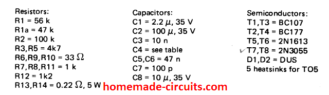
30 Watt Amplifier Parts List
Power Supply Circuit
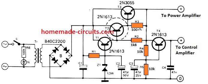
The power supply circuit for the above 30 watt amplifier is given below.
The 3 transistors are arranged in triple Darlington mode, where T1, T2, T3 are connected as an extremely high gain Darlington triplet. The output from this stage is used for the powering the main amplifier stage. The auxiliary output from T4 is used for operating the driver amplifier stage or the control amplifier stage.
R4, R5 devides the main supply output by 2, which means the output at the emitter of T4 is 50% less than the output from the 2N3055 emitter output.
This ensures that the control amplifier is operated with a supply that's one half of the supply which is used for operating the main amplifier stage. This in turn ensures that the consumption of the circuit as a whole is efficiently handled, and the dissipation through heat is kept at minimum.
Parts List for the power supply is as per the following data:
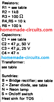
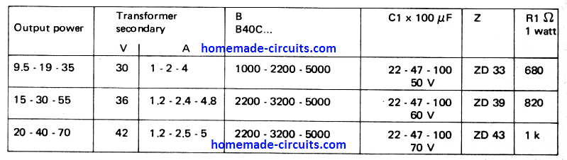
Transformer, bridge rectifier, filter capacitor, zener diode and the resistor R1 will have different values, depending upon the supply voltage, power output and loudspeaker selection for the amplifier.
The following table gives us the exact values of these elements as per the selection preference of the user.
Using IC TDA2004
For those who have a requirement for an amplifier, they should think about the below given 30 watt Monophonic Amplifier; this could simply be what you wish.
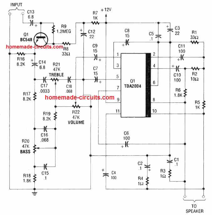
The design is low-cost and can perform for almost all power amplifier applications. This can work really well for applications like an intercom, a PA system, or, more than likely, an obvious traditional type of audio amplifier. You are going to naturally require a couple of these modules to build a stereo 30 + 30 watt audio, still the price must not be a matter of concern.
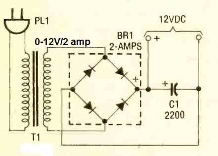
The amplifier is made using the TDA2004 audio-amplifier IC, as indicated in the circuit diagram, supplies 30 watts peak, 15 watts RMS, therefore it can easily work with 4 to 8 ohm speakers. Then of course you'll have to have a 12 volt DC, 2 amp power supply also to power the amplifier.
The one particular demonstrated in the following diagram will perform perfectly.



Questions & Answers
I want subwoofer amplfier using jrc4558 with transistor c2580 snd A11055.power supply 12v bsttery
currently i have to do a lab project that consist 8 transistors so i think this circuit is the best and suitable one. the thing is idont know what to put at power amplifier supply positive, control amplifier supply positive and music input source. i replace the speaker as R load=1M ohm. im using orcad capture.
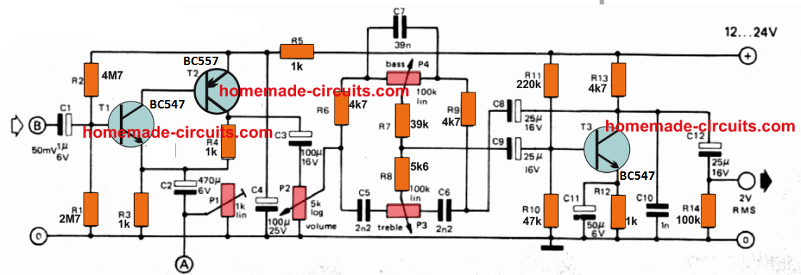
Sir please ,any schematic for tone control can’t see any in this article? Can this amplifier be upgraded to 1000w for 8ohm speaker? How with aid of a schematic,also advice on transformer power and any possible changes in the elements.
Evans, the tone control can be the same which was discussed in the previous post:
This circuit cannot be upgraded to 1000 watts
Ok