The simple telephone ring tone amplifier circuit I have explained in this article saves the inconvenience of picking the telephone handset while speaking over a call. This circuit also particularly becomes useful when there's a need of the conversation to become audible to a number of people or a group of people.
Introduction
When the conversation needs to become public the amplifier circuit simply needs to be switched ON so that rhe on going talks becomes amplified and can be heard loud and clear.
The most impressive feature of the proposed circuit design is that it does not require a direct or physical integration with the telephone line rather everything is done quite wirelessly.
The sensing of the telephone signals is done by the pick-up coil which may be placed very close to the telephone or the telephone wire.
The telephone pickup coil is made up of about 2000 to 3000 turns of 36 SWG super enameled copper wire wound over a plastic/paper former having a diameter of 2 inches.
Since this coil becomes the sole sensing agent should be made with lot of care and concentration.
How it Works
When placed near to the telephone wire, the signals from the wire are transferred to the coil through the principle of mutual conduction and the audio pulses which is created by talking over the telephone mic is picked by the coil and sent to the main circuit for amplification.
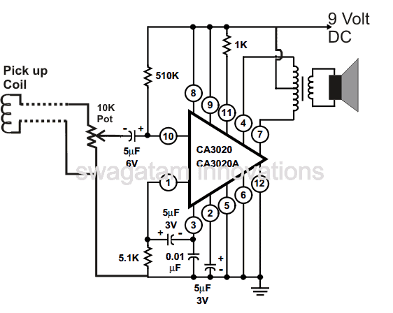
The amplifier unit basically consists of the IC CA 3020 which forms the heart of the circuit. It just requires a few other passive components for the IC to become fully operational as en efficient audio amplifier.
The sensed input from the coil is not more than 300 mV, but becomes quite sufficient for the IC CA3020 to process the input into an amplified version over the connected loudspeaker.
How to Setup the Circuit
After you finish assembling the circuit as shown in the figure, connect the pick up coil wire across the input of the amplifier and ground via the shown pot. Use shielded wire for this otherwise many unnecessary stray inputs may get into the amplifier. The pot acts as the sensitivity control or the volume control here.
Now switch on the power to the circuit.
Next gently place the pick up coil near the wire of the handset of the landline receiver.
Now as you lift the handset, the dial tone from the telephone should be heard loud and clear over the amplifier loudspeakers.
Make a call over the phone through another phone, all the audio during the calling procedure will be picked by the telephone amplifier circuit and converted into audible signals.
You may either use a battery for operating the circuit or a simple regulated power supply may be used. Alternatively you may use an AC DC adapter also for powering this circuit.
Using LF351
A telephone amplifier allows more than one person to listen in on a phone call. The unit detailed here, like other conventional units of this nature, does not necessitate a direct coupling to the telephone. The unique pick-up coil, on the other hand, includes a built-in rubber suction cap that allows it to be readily connected to the telephone base. This generates a rather faint signal from the magnetic field emitted by an inductive element within the phone, yet it can give good results if supplied to a low noise, high gain amplifier.
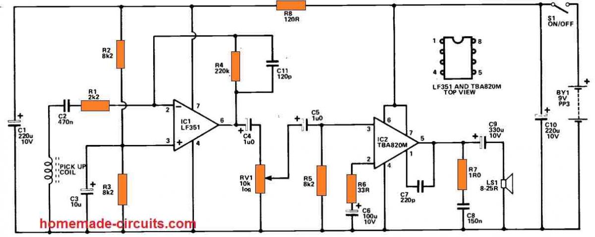
It is feasible to utilize an even simpler circuit in case a direct connection to the telephone is established. However, this would complicate setup and this maybe ILLEGAL to create a direct connection to a telephone in any case. The unit's preamplifier stage is based on IC1, which is a low noise op amp with a FET input stage. This is utilized in the usual inverting audio amplifier configuration, and the negative feedback circuit, R1, 4, adjusts the voltage gain to around 40dB. (100 times).
C11 lowers the gain somewhat at higher frequency to enhance the signal-to-noise ratio. C4 connects the preamplifier output to volume control, RV1, and C5 connects the signal to the power amplifier. The output stage employs the TBA820M, a class B amplifier with some hundred milliwatts rms of output power.
The device's closed loop voltage gain is governed by the R6 value, which is approximately 25dB. (180 times) with the stated value. This provides the needed extremely large overall gain in combination with the gain of the preamplifier. C7, R7, and C8 are required to sustain stability. The unit's quiescent current specification is approximately 5mA, although it can reach 50mA or more at high volume levels. With a little trial and error, the optimal placement for the pick-up coil on the telephone pedestal (not really the handset) may be determined.


Questions & Answers
Hello, thank you for your quick return and your answers, I will try to make this assembly with your advice.
Best regards
Sure, no problems!
Hello, your Telephone Amplifier Circuit “USING LF351” could be suitable for my personal project, but I would like to have some additional information.
– Is the signal-to-noise ratio of the assembly low?
– Can the assembly be supplied with 5v (instead of 9v)?
– Can I connect a wired headset instead of an audio speaker?
– Can we limit the output audio volume to avoid saturation? If this is possible, how can I do it?
Hello, yes the signal to noise ratio is very good for both the circuits
You can use 5V supply
You can use headphone between pin4 pin7 joined, and the positive in the first circuit.
The 10K pot can be used as the volume control.
I have impaired hearing. I want know if your telephone circuit will work with extension telephone
wireless cordless.There is base which connects to the mains with a transformer. The base hols the tel receiver vertically to get charged. we lift and use the handset. where should the pick up coil be placed.
please help me. my problem,the handset hearing volume is not sufficient for my ears.Narayan
Yes definitely the circuit will help in your case! You just have to place the ickup coil near wire entering the phone, or you can make a wire bundle by turning telephone wire a few times, so that the signal concentration increases around these turns, and then the pick up coil can be tied or placed around the telephone wire bundle for maximum signal reception….
Thank you for your prompt clarification. I will tell you the result after I get it ready which may take some time.
You are welcome!