In this post I have explained a voice modulator circuit which will change or transform an individuals unique voice into a completely new form. The new voice will be different to the original voice tone and unrecognizable.
The Circuit Concept
The characteristic tone of every individuals voice is specifically unique in all circumstances. How often we receive a phone call and simply by listening our interlocutor is able to know immediately who it is on the other side.
In many occasions we are able to recognize the presence of someone in a group or in a social gathering by just hearing to his or her voice, without even seeing the individual.
Would you be interested to change the timbre of a person's voice at will and make it appear to be completely different to other people? Or modify it even like a robot or a being from some another planet?
The proposed digital voice changer circuit is exactly designed to do this for you, and quite more.
Based on a voice modulator technology from HOLTEK, this voice changer chip digitally processes the fed voice signal in real time.
It does this by shifting the frequency spectrum associated with the voice therewith, upwards or downwards in seven incremental steps and the resultant output is heard as relatively much thinner or thicker in its frequency.
The result can be compared to that obtained a playback speed of a vocal information recorded on a tape is increased or decreased, except that it does without affecting or distorting the sped of the speech, additionally it also adds two special sound effects: vibrato and robot to a sample speech.
The first feature amongst the two modifies your voice with more tremulous while the second influences it simulating a robot kind of voice.
However under both the outputs the voice is fed to the IC through a standard electret microphone and the dimensioned output is reproduced through a dynamic speaker.
The entire system operates from a 9V battery.
Circuit Diagram
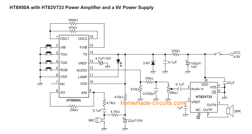
If you have problems with the above design, you can built the following original circuit from the datasheet of HT 8950.
You can replace the audio amplifier section with any other compatible amplifier circuit of your choice.
How it Works
The HT8950 includes, among other functional blocks of an amplifier with internal polarization microphone, an A / D of 8 bits, a static RAM (SRAM) and a D / A converter 8 bits.
The A / D and D / A work at a sampling rate of 8Khz, more than enough to cover the spectrum of the human voice (3Khz) and provides an output quality and very high signal to noise ratio (SNR) .
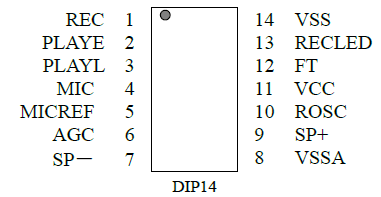
The following table summarizes the function of each pin for HT8950A version.No.
HT8950A Pinout Details
FUNCTION1
- OSC1 input of the oscillator2
- VIB input mode selector vibrato3
- TGU step input selector UP4
- TGD input selector step DOWN5
- ROB Input Selector mode step ROBOT6
- VSS negative supply line (GND)7
- NC Not connected8
- A0 output internal amplifier9
- AIN input of the internal amplifier10
- VDD Positive Power Line11
- LED LAMP Output for volume12
- AUDIO Audio Output13
- VREF Reference voltage internal amplifier14
- TS chip test input15
- FVIB control output frequency vibrato16
- OSC2 output of the oscillatorIn
Digital Voice Modulator
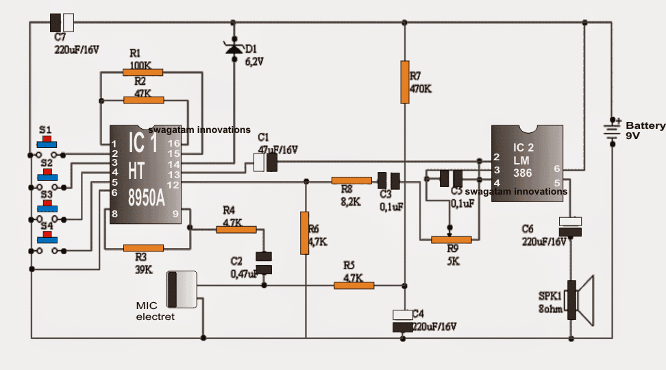
The system consists basically of a digital voice modulator and an audio amplifier, developed around respectively the chip IC1 (HT8950A) and IC2 (LM386I) the user's voice is captured by an electret microphone (MIC1) and reproduced normally or frequency offset in a dynamic speaker (SPK1). The entire assembly operates from a 9V battery (B1).
After being captured by the microphone, the voice signal is applied to the internal amplifier HT8950 through R4 C2 network.
The voltage gain of this amplifier, which is an open loop is typically equal to 2000, determined R3 (feedback resistor) and R4 (input resistance), being of the order of 8.3 times.
Resistors R5 and R7, together with the capacitor C4, the biasing conditions provide the electret element.An amplified and limited in bandwidth time, the injected HT8950 voice signal to the A / D bits where internal 8 is digitized at a nominal sampling rate of 8Khz. The sampling signal generator produces a time base, in turn controlled by an oscillator.
The frequency of the latter, which is about 512Khz, is determined by R2.After digitized voice signal is stored in a static RAM (SRAM), also controlled by the time base generator, a control circuit extracts information from the RAM and transferred to a latching register.
From the latter, the speech signal goes to a D / A converter the 8-bit reset to its original analog form or shifted frequency spectrum. This signal is available on the AUDIO output (pin 12).
Depending on the speed with which the SRAM data to the D / A are delivered, the original signal is reproduced with or without offset frequency spectrum.
This condition depends on the selected step by push-button switches S2 type (UP) and S3 (DOWN).
Especially, with every touch, move the speech spectrum S2 step up and S3 moves it a step down. In both cases, the sequence is cyclically repeated, as shown in Figure 3.
Once converted to its analog form, the speech signal is applied through C3 R8-network to a LM386 (IC2) amplifier, responsible for guiding the speaker (SPK1) and make it audible.
The resistor R6 acts as a pull-down of the D / A HT8950 internal current mode and trimmer R9 as master volume control system. Other components comply auxiliary functions.
D1 particularly limits the supply voltage to a safe value HT8950 (below 2.8V) and R1 vibrato frequency fixed at 8 Hz, approximately.
List of Materials
Resistance (1 / 4W 5%)
- R1-100K
- R2-47K
- R3-39K
- R4, R5, R6-4,7K
- R7-470
- R8-8,2K
- R9-5K, Trimmer, 1 lap
- Capacitors
- C1-4,7uF / 16V electrolytic
- C2-0,47uF (474), ceramic
- C3, C5-0,1uF (104), ceramic.
- C4, C6, C7-220uF / 16V, electrolytic.
Semiconductors
- Zener diode D1-6,2V / 0.5W
- Integrated CircuitsModulator voice IC1- HT8950A
- IC2- LM386 audio amplifier
- Transducers MIC1- electret microphone, miniature
- SPK1- Speaker 8 / 0.25W
Electromechanical
S1, ..., S4-push-button switches Miniature NAJ1- type connector for 9V battery snap.
Another Simple Voice Modulator Circuit
The circuit diagram for the voice modulator can be seen in the below given figure.
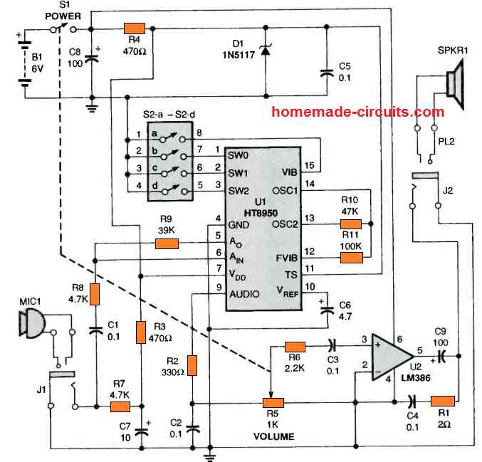
Four dry cells generate the required 6 V for operating the LM386 audio amplifier, U2. Resistor R4 and Zener-diode D1 are used for stepping down and controlling the battery voltage to 3.6 V to operate the HT8950 signal-processor device, U1. S1 is the power switch which is also the integrated part of the volume-control potentiometer, R5. Capacitors C8 and C5 deliver smoothing of the DC supply for the circuit.
While using the voice modulator circuit, the voice signal is detected by electret MIC1 and the signal is AC coupled by capacitor C1 to pin#6 of the IC U1 (pin#6 is the input pin of the IC's preamplifier stage). Resistors R8 and R9 are configured to fix the gain of the internal preamplifier to around 8, which is determined by the equation:
Vout = (R9/R9) x Vin
The output preamplifier stage of the IC after passing through a buffer stgae is applied to the chip's internal, 8 -bit, analog-to-digital converter. That voice signal is then sampled by the converter at 8 kHz through a time-base generator. Also, the internal SRAM memory saves the 8-bit digital figures in it.
At the same time, the control circuit of the IC control provides the clock pulses to the SRAM data out to a digital-to-analog converter (DAC). This stage subsequently reproduces the analog voice signal through the output pin 9.
The processed signal after this moves via a low-pass filter created through the amplification via R5 which finally drives the loudspeaker SPKR1. The potentiometer R5 is used for controlling the volume of the output modulated voice signal.
If the speech information is switched in and out of U1's SRAM with precisely the same frequency, the original voice signal gets reproduced without any modulations or changes.
However in case the digital information is modified prior to transferring it via the DAC, some very bizarre sound effects could be generated! The 4-step DIP switch, S2, is employed to establish the working modes of the IC HT8950 (see Table 1).
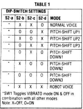
Voice Modulation Effects
The chip HT8950 could be adjusted for NORMAL VOICE, ROBOT VOICE, and several other unique and weird modes.
A vibrato effect could be introduced to every single of these modes. In the normal setting the procedures does not require any explanation.
However, for the ROBOT VOICE setting, it introduces echo and reverb effects by slowing down portion of the digital audio then mixing the delayed signal with the original audio. In the pitch shifting modes it correspondingly enables the speeding up or reducing a recording data, during playback.
The voice pitch is implemented by altering the clock pulse ratio of the ICs internal time-base generator. The vibrato effect is produced once the IC HT8950 automatically moves the input signal pitch up and down alternately at the frequency of 8 Hz.
Questions & Answers
i am unable to get HT8950A IC. What can I use instead of it ?
You can search for other alternative designs. Or you can get the IC from online stores like, amazon, eBay, aliexpress.
Hello , I am really interested in your project.
I tried both schematics but it is not working for me. I don’t have a zener diode so i directly supplied everything with 3.5v . However , i think that i am making a mistake since the Chip and Microphone should not be both supplied the same voltage right ? how can i do this without the zener ?
The second diagram is taken directly from the datasheet of the IC, and it should work without any issues….4.5V will be required otherwise the right side IC might not operate correctly….
good evening sir i noticed that you did not used pin 10 which is the VDD, whats the reason..thank you
Thank you kyle for pointing out the mistake, I have updated the original diagram from the datasheet, please check it out for your reference
Hello sir, I was wondering if u can show me the lay out of this circuit on a bread board sheet since it can be a little complicated around ic2, if it's not too much trouble sir. My email is besrat10mekonnen@mail.com
Thank you
did you check the datasheet, which has explained many important parameters regarding the design, you can probably change your existing design and try one of those recommended deigns as per the datasheet, because the datasheet will give you the most reliable suggestions…for me it could e difficult to diagnose the circuit without a until it is checked practically using meters.
I tried every way possible… at the final stage when I connected the 9v battery on the breadboard the speaker just kind of made a pumped sound then no response over and over again.. I even re-arranged the components wasted more than 4 ic on 1 circuit idk but it's seems to be not functioning can you send me your email please and take a look what I did wrong. This project is due next week and I need a little help thx my email is besrat10mekonnen@mail.com
4.7k preset in place of 5K is fine, the problem could be somewhere else, not sure exactly where….you can refer to the following datasheet and check if there's anything that you can include to improve your circuit or perhaps identify the fault
https://www.sparkfun.com/datasheets/Components/General/8950v110.pdf
it would be helpful if you can show me the strip board version of the circuit. I am really interested on this project and would like to see it work thank you
I tried your circuit as part of my project on a broad with all the right components but the circuit seems to be not functioning, the only part I found difficult was the 5k trimmer which was unavailable so I replaced it with a 4.7k….. do you think this is the reason why my circuit is not functioning correctly or any points that could help please, its for my college project
Hello BC, I am sorry that would be difficult because I never use breadboard for my experiments, I have so far always relied on soldering the parts on veroboards for the results.
Sir could u please share pic of shouldered circuit…
Manshi, you are confusing the word ‘soldered’ with ‘shouldered’. Shoulders are for carrying a load or for crying on if they belong to someone else.
Hello, I did not get a chance to build this yet, if I happen to make it in near future, I’ll share the pics
Can i ask you sir if the ic HT8950A here can be change? Or where can i buy this ic in the philippines?
https://www.homemade-circuits.com/2015/03/digital-voice-changer-circuit.html
you can try buying it from an online part store. that's perhaps the easiest way to find an obsolete kind of part
Sorry Sir, for disturb you again. I am not that smart enough to make the circuit (https://www.homemade-circuits.com/2012/03/how-to-make-simple-12-v-1-amp-switch.html ) I was trying to change the output of this smps which is easily available and costs only 30rs
s1.postimg.org/vljsl75f3/2015_02_26_00_10_27.jpg
the best thing would be to use a 7805 IC with the output of the smps, this will save you from all sorts of risks and hassles…
I may changed 4148 to zenor diode as both looks same. Can I apply any zenor value like 5/6 and will it work to adjust the output ?
yes it will work accordingly
In local mobile charger we generally find the smps circuit which explain by you in ( https://www.homemade-circuits.com/2013/10/12v-24v-1-amp-mosfet-smps-circuit.html ) I found in 12 volt smps circuit that both have used the exact 100% same circuit and they only cut the zenor diode and put another one to get 12v output. I tried to do same with 15volt zener and mine one got burned intently.
Can you plain again in easy way to modify the output voltage only. Like 5 / 6 volt output from 12volt smps circuit. 12 volt smps circuit are easily available at rs 30 and have 2 types of smps circuit which you explained
https://www.homemade-circuits.com/2012/05/cheapest-smps-circuit-using-mje13005.html
https://www.homemade-circuits.com/2013/10/12v-24v-1-amp-mosfet-smps-circuit.html
SMPS Circuit Using MJE13005 which I have is working very well and have more life in compare to the others. I wish to change the output to 5 volt ( local mobile charging smps circuit are also available in market but they have very sort life, so do not want to use that ) I found your some article like https://www.homemade-circuits.com/2012/11/how-to-modify-smps-circuit.html
but SHUNT REGULATOR things are some difficult topic for me.
Regards
changing the 12v zener to 15v will not burn any smps circuit, it might ahve happened due to some other fault, you can try it again with another board for confirmation.
check out the following design, it is by far the most reliable one and can be set to any desired voltages, without damaging anything:
https://www.homemade-circuits.com/2012/03/how-to-make-simple-12-v-1-amp-switch.html