In this post I have explained a simple water flow meter/sensor circuit using hall effect sensor and a pulse counter circuit.
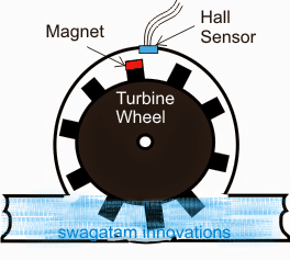
Referring to the diagram shown below, we can see an arrangement consisting of a circular enclosure having a couple of pipes drilled in and a circular turbine shaped wheel installed inside the enclosure.
How it Works
The pipe connections allow water to flow in through one of the inserts and flow out from the other side of the enclosure insert.
The extended turbine propellers or wings are purposely placed in path of the flowing water so that it begins rotating in response to the force exerted by the flowing water on the shafts.
A magnet can be seen attached at the outer end of one of the turbine propellers, and a fixed complementing hall effect magnetic sensor at the outer periphery of the enclosure.
When the turbine rotates in response to the water flow rate or flow pressure, the attached magnet cuts through near the hall effect sensor inducing a triggering voltage into it with each rotation cycle.
Integrating with a Digital Decoder Circuit
This pulsed voltage from the hall effect sensor corresponding to the flow rate of the water is appropriately fed to a cascaded IC 4033, 7 segment decoder circuit for indicating the recorded water consumption at any particular instant.
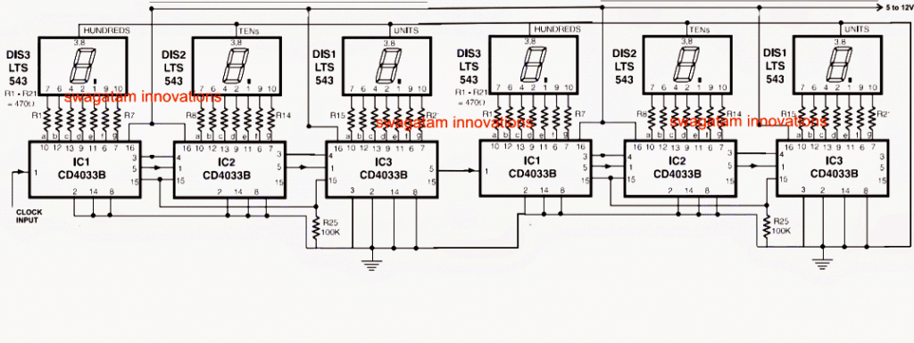
The image above shows a 3 digit pulse counter, the clock input of the circuit may be integrated with the hall sensor triggers for getting the intended water consumption rate.

Questions & Answers
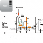
Hello Sir, I have a problem with our water system at home, the AC motor of our pressure tank keeps on running even there’s no water from the deep well. If this happens without anyone to manually switch off the motor if there is no water coming out from its water pump, it might destroy the pump and will waste a lot of power/ electricity Sir ..I am hoping for your help again Sir…Thank you so much …..
Hi Allan, you can try the first one which is the easiest option given in the following article:
https://www.homemade-circuits.com/municipal-water-supply-sensor-pump/
The circuit will not start the pump automatically. You will have to connect a push button switch across the two arrow points. Pressing this button will toggle the relay ON and the motor will start pumping out water. The moment water connects the probe terminals you can release the switch, since now the water bridge will latch the relay and keep the motor running… until the water from the source is exhausted and there’s no water to bridge the probes. The motor will stop.
Old cassete tape head can be used instead of Hall sensor. I appricate the circuit designer.
yes it can be tried….it should work