In this post I have explained a two op amp IC 741 and LM358 based auto cut off battery charger circuits which are not only accurate with its features but also allows a hassle free and quick setting up of its high/low cut-off threshold limits. High current batteries can e also charged using these circuits.
The idea was requested by Mr. Mamdouh.
Circuit Objectives and Requirements
- As soon as I connect the external power automatically it will disconnect the battery and supply the system, in the meanwhile charging the battery.
- Overcharging protection ( which included in the above design).
- Battery low and full charging indications (which included in the above design).
- Also i don't know what is the formula to help how to determine the voltage required across my battery to charge it with( battery will be extracted of old laptops.total will be 22V with 6 apms at no load)
- Furthermore, I don't know the formula to indicate how long my battery will last, and how to calculate the time if i want a battery to last me two hours.
- Also, the cpu fan will supplied by the system too. It would be great too to add the option of a dimmer, my original plan was to vary between 26-30 v not need much more than that.
Circuit Diagram
The Design
In all of my previous auto cut off battery charger controller circuits I have used a single opamp for executing the full charge auto cut-off, and have employed a hysteresis resistor for enabling the low level charging switch ON for the connected battery.
However calculating this hysteresis resistor correctly for achieving the precise low level restoration becomes slightly difficult and requires some trial and error effort which can be time consuming.
In the above proposed high current auto cut off low high battery charger controller circuit two opamp comparator are incorporated instead of one which simplifies the set up procedures and relieves the user from the long procedures.
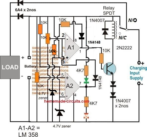
Referring to the figure we can see two opamps configured as comparators for sensing the battery voltage and for the required cut-off operations.
Assuming the battery is s 12V battery, the lower A2 opamp's 10K preset is set such that its output pin#7 becomes high logic when the battery voltage just crosses the 11V mark (lower discharge threshold), while the upper A1 opamp's preset is adjusted such that its output goes high when the battery voltage touches the higher cut off threshold, say at 14.3V.
Therefore at 11V, the A1 output gets positive but due to the presence of the 1N4148 diode this positive stays ineffective and blocked from moving further to the base of the transistor.
The battery continues to charge, until it reaches 14.3V when the upper opamp activates the relay, and stops the charging supply to the battery.
The situation is instantly latched due to the inclusion of the feedback resistors across pin#1 and pin#3 of A1. The relay becomes locked in this position with the supply completely cut off for the battery.
The battery now begins slowly discharging via the connected load until it reaches its lower discharge threshold level at 11V when the A2 output is forced to go negative or zero.
Now the diode at its output becomes forward biased and quickly breaks the latch by grounding the latching feedback signal between the indicated pins of A1.
With this action the relay is instantly deactivated and restored to its initial N/C position and the charging current yet again begins flowing towards the battery.
This auto cut off low high battery charger circuit can be used as a DC UPS circuit also for ensuring a continuous supply for the load regardless of the mains presence or absence and for getting an uninterrupted supply through out its usage.
The input charging supply could be acquired from a regulated power supply such as an LM338 constant current variable constant voltage circuit externally.
How to Set the Presets
- Initially keep the 1k/1N4148 feedback disconnected from the A1 op amp.
- Move the A1 preset slider to ground level, and move the A2 preset slider to the positive level.
- Through a variable power supply, apply 14.2 V which is the full charge level for a 12 V battery across the "Battery" points.
- You will find the relay activating.
- Now slowly move the A1 preset towards the positive side until the relay just deactivates.
- This sets the full charge cut off.
- Now, connect the 1k/1N4148 back so that the A1 latches the relay in that position.
- Now slowly adjust the variable supply towards the lower discharge limit of the battery, you will find the relay continues to remain switched OFF due to the above mentioned feedback response.
- Adjust the power supply down to the lower battery discharge threshold level.
- After this, begin moving the A2 preset towards the ground side, until this turns A2 output to zero which breaks the A1 latch, and switches ON the relay back to the charging mode.
- That's all, the circuit is fully set now, seal the presets in this position.
Answers for other additional questions in the request are as given under:
Formula for calculating full charge cut off limit is:
Battery voltage rating + 20%, for example 20% of 12V is 2.4, so 12 + 2.4 = 14.4V is the full charge cut off voltage for a 12V battery
To know the battery back up time the following formula can be used, which gives you the approximate battery back up time.
Backup = 0.7 (Ah / Load Current)
Another alternative design for making an automatic over/under charge cut-off battery charger circuit using two op amps, can be seen below:
How it Works
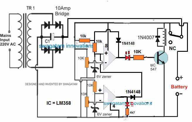
Assuming there's no battery connected, the relay contact is at N/C position. Therefore when power is switched ON, the op amp circuit is unable to get powered and stays inactive.
Now, suppose a discharged battery is connected across the indicated point, the op amp circuit gets powered through the battery. Since the battery is at a discharged level, it creates a low potential at (-) input of the upper op amp, which may be less than the (+) pin.
Due to this, the upper op amp output goes high. The transistor and the relay activate, and the relay contacts moves from N/C to N/O. This now connects the battery with the input power supply, and it begins charging.
Once the battery is fully charged, the potential at (-) pin of the upper op amp becomes higher than its (+) input, causing the output pin of the upper op amp to go low. This instantly switches OFF the transistor and the relay.
The battery is now disconnected from the charging supply.
The 1N4148 diode across the (+) and the output of the upper op amp latches so that even if the battery begins dropping it has no effect on the relay condition.
However, suppose the battery is not removed from the charger terminals, and a load is connected to it so that it begins discharging.
When the battery discharges below the desired lower level, the potential at pin (-) of the lower op amp goes lower than its (+) input pin.
This instantly causes the output of the lower op amp to go high, which hits the pin3 of the upper op amp. This instantly breaks the latch, and switches ON the transistor and the relay to initiate the charging process yet again.
PCB Design
Adding a Current Control Stage
The above two designs can be upgraded with a current control by adding a MOSFET based current control module, as shown below:
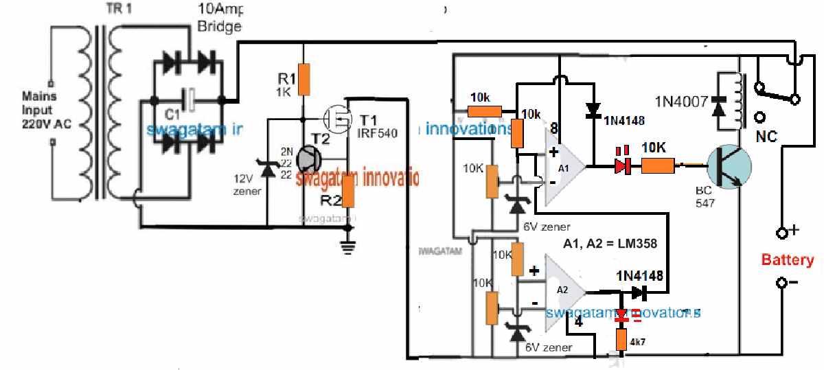
R2 = 0.6 / charging current
Adding a Reverse Polarity Protector
A reverse polarity protection can be included to the above designs by adding a diode in series with the positive terminal of the battery.
Cathode will go the battery positive terminal, and anode to the op amp positive line.
Please make sure connect a 100 Ohm resistor across this diode, otherwise the circuit will not initiate the charging process.
Removing the Relay
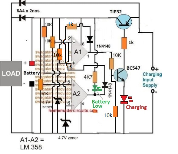
In the first auto cut off based battery charger design, it may be possible to eliminate the relay and operate the charging process through solid state transistors, as shown in the following diagram:
How the Circuit Works
- Let's assume A2 preset is adjusted at 10 V threshold, and A1 preset is adjusted at 14 V threshold.
- Suppose we connect a battery that is discharged at an intermediate stage of 11 V.
- At this voltage pin2 of A1 will be below its pin3 reference potential, as per the setting of the pin5 preset.
- This will cause the output pin1 of A1 to be high, turning ON the transistor BC547 and the TIP32.
- The battery will now start charging via TIP32, until is terminal voltage reaches 14 V.
- At 14 V, as per the setting of the upper preset, pin2 of A1 will go higher than its pin3, causing the output to turn low.
- This will instantly switch OFF the transistors, and stop the charging process.
- The above action will also latch the A1 op amp through the 1k/1N4148 so that even if the battery voltage drops to the SoC level of 13 V, the A1 will continue hold the pin1 output low.
- Next, as the battery begins discharging via an output load, its terminal voltage begins dropping, until it has dropped to 9.9 V.
- At this level, as per the setting of the lower preset, pin5 of A2 will drop below its pin6, causing its output pin7 to turn low.
- This low at pin7 of A2 will pull pin2 of A1 to almost 0 V, such that now pin3 of A1 becomes higher than its pin2.
- This will immediately break the A1 latch, and the output of A1 will once again turn high, enabling the transistor to switch ON and initiate the charging process.
- When the battery reaches 14 V, the process will repeat the cycle yet again
How Set the Presets
Initially keep the wiper arm of A1 preset to the ground level, and keep the wiper arm of the A2 preset at the positive supply level.
Take a variable power supply, adjust its voltage to the full charge level of the battery and connect the supply to the circuit from the "battery side" (not from the emitter side of TIP32).
You will see that the RED LED has illuminated.
Now, slowly adjust the A1 preset until the RED LED just shuts off.
The full charge cut off is now set.
After this, decrease the power supply voltage to a point which corresponds to the low discharged level of the battery at which the charging needs to be restarted.
Now adjust the A2 preset slowly until the Green LED and the RED LED both illuminate together.
Your low battery recharge level is now set.
That's all, now you can try testing the circuit on a real discharged battery, but this time make sure to connect the charging supply from the emitter side of TIP32.
Single Op amp Automatic Battery Charger Circuit
Automatic battery chargers just aren't economical, but the protection they provide from overcharging and potential battery degradation is extremely appealing.
The circuit illustrated here is meant to be a low-cost replacement to commercially available fully automated chargers.
The concept is to pick a basic battery charger and install an add-on module that will automatically check the condition of the battery and turn off the charge current as soon as the battery gets fully charged.
How it Works
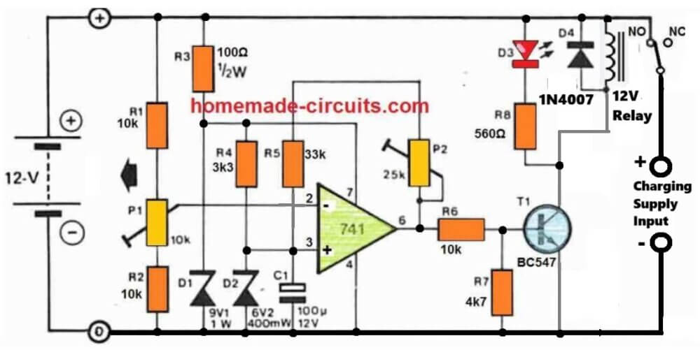
The circuit is simply made up of a comparator that checks the battery voltage in relation to a preset reference value.
When the battery voltage surpasses a certain peak value, a relay is turned OFF, causing the charge current to be terminated. When the battery voltage declines below a certain specified lower limit, the relay activates, allowing the charge current to flow again.
A 741 op-amp serves as the comparator. The op-amp's supply voltage is stabilized by R3 and D1, thus it is immune to fluctuations in battery voltage.
The reference voltage, that is supplied to the op amp's non-inverting input through R4 and D2, is generated through this stabilized supply.
The reference voltage is compared with the battery charge voltage, via the resistive divider.
As the battery charges, the voltage at the inverting input of the op-amp finally becomes higher than that on the non-inverting input, causing the output of the op-amp to go low, switching off T1 and T2.
This causes the normally closed contact of the relay to open, cutting off the input charge current to the battery.
The battery full level will then illuminate LED D3 to show that it is completely charged.
A part of the op-amp output voltage is sent back to the inverting input through P2 and R5 to discourage the battery from reverting to the charging mode at the smallest reduction in the battery voltage.
The op-amp therefore works in the same way as a Schmitt trigger, with P2 determining the level of hysteresis, or the battery potential where the op-amp output can turn low again.
How to Setup
The easiest way to setup the circuit is to use a adjust stabilized voltage to simulate the battery voltage.
An input voltage of around 14.5 V is determined, and P1 is tuned so that the relay simply clicks off (opens).
The voltage of the 'battery' is then lowered to 12.4 V, and P2 is tweaked until the relay reconnects and switches ON. Because P1 and P2 will have an effect on each other, the operation should be done numerous times.




Questions & Answers
Hi Sir
I need a Charger Cutoff @ 82.5V and Reconnect @ 75V and the relay is on at the time of charging. Can u suggest a circuit.
Hi Safarudheen,
You can try the last circuit.
Just replace R3, R8 with 10k and replace BC547 with BD139
For this circuit “Single Op amp Automatic Battery Charger Circuit’ how would I add a discharging circuit. I receive many (~29vdc LION) new batteries, and my procedure is to discharge them first to the low voltage cutoff of ~22VDC. Scenario is as follows: 1. new battery received. 2. Connect to charger/discharger (BCD). 3. I push a discharge button, and battery begins discharge at 1A. 4. When BCM detects BAT=volt is 22vdc, the charge cycle begins. 5. At ~29vdc the Battery is charged and the BCM stops. Or have a button to charge and one for discharge.
I have the circuit “charge-discharge-battery-life-testing-ssetup-circuit.jpg” drawn in Falstad Simulator. The circuit works, kinda. My battery limits are 22 low cutoff and 29vdc as high cutoff. I have connected a 1 A current source at the “Charging Supply Inputs”. Can you help me (point me in the right direction) set the correct component values so Bat+ charges at 21-22VDC and discharges 28-29vdc? Also this circuit will use a transformer and bridge rectifier as charging source. Thank-you in advance
The circuit will work with 100% accuracy, if it is set correctly, which can be slightly difficult for a newcomer.
https://www.homemade-circuits.com/wp-content/uploads/2025/11/charge-discharge-battery-life-testing-ssetup-circuit.jpg
Make sure to use 29V DC “fixed” from the charging side.
To setup the circuit do the following steps:
Initially remove the P2 connection.
Do not connect any supply from the charging input side.
Move P1 wiper fully towards R2 side (ground side).
Apply 29V from the battery side (with no battery connected).
You will see the relay clicking ON.
Now slowly move P1 towards R1 (positive side), until the relay just clicks OFF (N/C). Fix the preset with glue…Your full charge battery cut-off is fixed.
Next adjust P2 to maximum resistance, without any connection to the circuit (P2 connection open with maximum resistance set).
Now without turning off the 29V from the battery side restore the P2 connection.
Now, reduce the battery side supply voltage to 22V.
Start reducing the P2 value until the relay just clicks ON.
Seal P2 with glue….your low battery turn ON adjustment is done!
Now you can remove the DC supply from the battery side and put it normally on the charging input supply side (on the right side) and battery on the left side as shown in the diagram….and start the charging/discharging process…
I have designed th circuit as per your requirements, you can check it in the below given link, it is fully automatic:
https://www.homemade-circuits.com/wp-content/uploads/2025/11/charge-discharge-battery-life-testing-ssetup-circuit.jpg
Please make sure to make R3 470 ohms and R8 1k if 29V is used, and also replace the opamp with an LM358 opamp…
Hello Sir,
Can we use R feedback lower than 1k? I found the range of lower threshold and auto cut-off is depended on this R.
What is the purpose of 2 diode 1N4007 at the emitter lead of the transistor?
Thank you,
Hello Prapan,
Yes, in the first diagram you can replace the feedback resistor lower than 1k. Those two diodes are added to make sure the transistor does not activate through any false leakage offset voltage from the opamp output.
hi Sir,
It works, it cuts off and switches on at both desired voltages. I apply it for 24 volt charger. Anyway, I found that the relay is flickering on and off at both high/low cut off for a minute before stopping. It happens when the input voltage is closed to the zener diode 4.7 v. Should I increase the R feedback to be higher than 1k to solve this problem?
Thank you,
Prapan
That’s great Prapan,
To stabilize the relay you should actually reduce the feedback resistor value so that the relay kind of latches in that position until the battery voltage reaches the other extreme threshold.
You can also try adding a 220uF capacitor directly across the relay coil to prevent the initial relay chattering.
Hello sir, can I use the lm358 circuit to charge a car battery that is 65 amp hours?
Hello Amir, you can use any standard opamp for these circuit. The opamp does not handle the battery, the relay does.
Ref: LM358 Battery Charger ( Removing the relay and replace with TIP32)
Hi Swagatam, I would like to install a digital Volt/Amp meter (Model No. M3430) into my battery charger, so that I can read the Voltage & AMPS of the battery while it is charging. I don’t know if this is possible? If it is possible can you please assist me as to how to connect it to the battery charger cct.
I don’t know how to send the meter diagram to you. If you can give that info. Then I will send the diagram to you.
Your assistance will be much appreciated.
Regards
Jan
Hi Jan,
You can connect it in the following manner:
https://www.homemade-circuits.com/wp-content/uploads/2025/02/how-to-wire-digital-Volt-Amp-meter-Model-No.-M3430-circuit-diagram.jpg
Thank you Swagatam, I really appreciate your help.
You are welcome Jan!
Hi Jan,
Sorry for the trouble, there was a mistake in my previous diagram. The ammeter wires are supposed to be in series with the negative of the load, but I connected the meter in series with the positive of the load, which is a standard practice. But as per the meter specifications it must be connected in series with the load negative.
I have replaced the previous diagram with the new one, please check it….
Hi Swagatam,
Ref. LM358 Battery Charger ( Removing the relay and replace with TIP32)
I have wired up the digital Volt/Amp meter as per your diagram. It works 100%.
I want to thank you for all your assistance with this project.
Just another question: You would not perhaps know of a software package that I can use to make front panel face plates?
Kind Regards
Jan
That’s great Jan, I am glad it worked.
For the front panel designing software, did you try the following ones?
https://www.schaeffer-ag.de/en/front-panel-designer/?lang=en
https://www.emachineshop.com/front-panel-design-software/
You can also try FreeCad, or CorelDraw.
Swagatam, is the diagram currently on your post the correct one. Sorry I just want to confirm this as I am getting a bit confused. So you have a + red wire from the meter going to the – of battery and then a + red wire from the + battery terminal going to the + side of the charger?
Yes, that’s right, that red wire is the thick wire of the meter which measures the current.
Here’s a schematic representation of the previous diagram:
https://www.homemade-circuits.com/wp-content/uploads/2025/02/how-to-wire-digital-Volt-Amp-meter-Model-No.-M3430-with-loads-below-30V.jpg
Hi Swagatam,
Ref. Removing the relay & Presets.
I have completed the battery charger circuit on my breadboard and it seems to be working fine.
However I don’t have a battery available at the moment to test the final step of charging a battery.
Can I replace the battery with a variable power supply? That way I can verify if the charger will switch ON/OFF at the presets settings by observing the red LED.
My concern is the possible damage to the variable power supply.
Your advice will be much appreciated.
Regards
Jan
Hi Jan,
Can you please show me the link to the schematic? I guess you are referring to an opamp based circuit which uses presets.
By the way, you can replace the battery terminals with a variable power supply DC, but then no other power supply should be used from the input side. In this way you can confirm the presets operations. The battery side power supply itself powers the opamp and the relay.
Yes it is the schematic with the TIP32 in place of the relay.
Thank you for your reply.
Regards
Jan
No problem Jan, glad I could help!
Hi Swagatam,
Ref. Removing the relay
In our discussion you refer to ZX which is situated on the 18V solar panel cct.
Then you refer to ZY. Where is this Zener situated?
Regards
Jan
Hi Jan,
I may be referring to the last circuit presented in the following article:
https://www.homemade-circuits.com/battery-deep-discharge-protection-circuit/
Let me know if you have any further doubts in this regard.
Hi Swagatam,
Ref. Removing the relay
I have build this cct on my breadboard tested it with your “How to set the presets procedure” and everything worked 100% using my external power supply.
Problem is the transformer I want to use is 9-0-9 V 50VA of which I will use the 18V tapping’s. I think this is to high? If required how can I lower the voltage to the required value?
Your assistance will be much appreciated.
Regards
Jan
Thank you Jan, for updating the info! Glad it worked for you!
To regulate the power supply to a lower value you can use the following concept:
https://www.homemade-circuits.com/wp-content/uploads/2022/09/solar-regulator-emitter-follower.jpg
You can replace the transistor with a 2N3055 or similar. The resistor value will depend on the battery current requirement. Mostly a 100 ohm 1 watt will do the job.
Also, connect a 4.7k dummy load across the emitter and ground of the circuit which will allow you to check and adjust the output voltage with a meter before connecting the battery.
The zener diode value (minus 1) gives the output voltage values.
can this circuit work between 5v to 12.6 Therashold cc/cv for Li-ion battery charging or in Current circuit how many Ampere Limit .
Yes, the cut-off can be adjusted between 5V and 12.6V, but for CC/CV you must include them in your input power supply circuit, let me know if you need any further assistance on this…
sir,i congratulate you for sharing your knowledge for free on internet.but the circuit schematics which u put in this page are tough to understand,they appear like complicated puzzle for soldering.why dont u share schematic created in proteus or multisim.the schematics from proteus are simple to understand and there is very less error while soldering the components.
Thank you Saikrshna, I appreciate your feedback, however, I feel that schematics are the standard way to represent circuit diagrams, and I find them easier to draw. Nevertheless, if you are finding it difficult to understand, please let me know about it, I will try to solve them for you…
Thank you very much for your quick response, but I think I expressed myself wrong. I just need a circuit to put on the multimeter so that the multimeter shows the value by 100…. Example when measuring 300 microvolts on the multimeter it shows 300 millivolts. From already thank you very much.
Thanks Carlos, I think you can connect the multimeter where the 1mV moving coil meter is connected in the diagram, for getting the necessary conversions.
Hello, good afternoon, Mr. Swagatam. You have a circuit available to measure microvolts, starting from 100 microvolts. Since the 3 multimeters I have cannot measure it… Thank you very much Mr. Swagatam.
Hello Carlos,
Unfortunately i do not have any microvolts meter circuit with me at the moment, however I have a microamp meter circuit as giiven below:
https://www.homemade-circuits.com/microamp-meter-circuit/
In the first circuit, I think you can try removing the SW1 switch and all the associated resistors, and apply the microvolt across pin#3 and ground and check if that helps to get any reading on the meter.
Hi
I want to make 6v battery backup with 10 to 18v input, my load is 500ma
My mail id hirenbhai@gmail.com
Hi,
You can try one of the concepts explained in this article:
https://www.homemade-circuits.com/simple-dc-ups-circuit-for-modemrouter/
Mr.swagatam,I just want to thank you for this great website. I have learnt a lot from you and still learning more.God bless you.
Thank you so much Julius. I am glad this site is helping you to learn more. Please keep up the good work.
Hi Swagatam,
How to build a low battery indication circuit for my 72v 50Amp LiFePo4 battery pack.Can you please help me on it?
Hi Manjunath,
You can try the following concept:
https://www.homemade-circuits.com/low-battery-indicator-circuit-using-two/
Hlo sir, good evening.. Regarding the second last circuit using Lm358 and TIP 32 transistor, can this circuit be used for charging a 6v,4.5Ah battery? Any changes be applied as regarding the zener or any thing like that? I just need an opamp charger for 6v with auto cut.
Hi Binoj,
Yes you can charge a 6V battery with that circuit. You will have to change the zener diodes to 3 V zener diodes. However you do not need this complicated circuit to charge a 6V battery, you can simply do it with a LM317 or LM338 IC based charger. You just have to set the output voltage to 7 V that’s all, and your 6 V battery will be charged perfectly with a longer life.