In this post I will show how to construct a wireless servo motor circuit which can control 6 servo motors wirelessly on 2.4 GHz communication link.
Introduction
The project is divided into two parts: a transmitter with 6 potentiometers and a receiver circuit with 6 servo motors.
The remote has 6 potentiometers to control 6 individual servo motors independently at receiver. By rotating the potentiometer, the angle of the servo motor can be controlled.
The proposed circuit can be used where you need controlled motion, for example arm of a robot or front wheel direction control of RC car.
The heart of the circuit is NRF24L01 module which is a transceiver; it works on ISM band (Industrial, Scientific and Medical band) it is the same frequency band which your WI-FI works.
Illustration of NRF24L01 Modules:
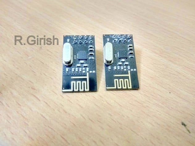
It has 125 channels, it has maximum data rate of 2MBps and it has theoretical maximum range of 100 meters. You will need two such modules to establish a communication link.
Pin configuration:
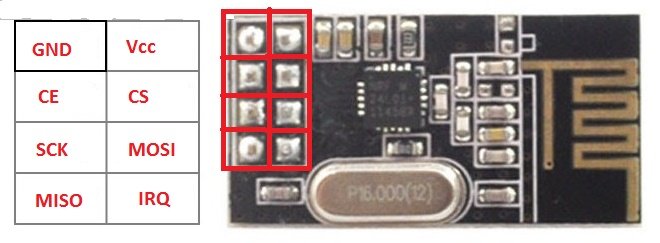
It works on SPI communication protocol. You need to connect 7 of the 8 pins to Arduino to make this module work.
It works on 3.3 V and 5V kills the module so care must be taken while powering. Fortunately we have on board 3.3V voltage regulator on Arduino and it must be powered only from 3.3V socket of Arduino.
Now let’s move on to Transmitter circuit.
Transmitter Circuit:
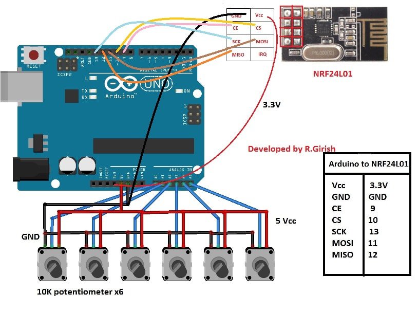
The circuit consists of 6 potentiometer of 10K ohm value. The middle terminal of 6 potentiometers is connected to A0 to A5 analog input pins.
Tabulation is given beside the schematic for NRF24L01 to Arduino connection; you may refer, if you have any confusion in circuit diagram.
This circuit may be powered from USB or 9V battery via DC jack.
Please download the library file here: github.com/nRF24/
Program for Transmitter:
//----------------------Program Developed by R.Girish------------------------//
#include <nRF24L01.h>
#include <RF24.h>
#include <SPI.h>

RF24 radio(9, 10);
const byte address[6] = "00001";

#define NUM_POTS 6
const int pots[NUM_POTS] = {A0, A1, A2, A3, A4, A5};
const char* servoNames[NUM_POTS] = {"Servo1", "Servo2", "Servo3", "Servo4", "Servo5", "Servo6"};

const int threshold = 20;
int potValues[NUM_POTS] = {0};
int angleValues[NUM_POTS] = {0};
int checks[NUM_POTS] = {0};

void setup() {
  Serial.begin(9600);
  radio.begin();
  radio.openWritingPipe(address);
  radio.setChannel(100);
  radio.setDataRate(RF24_250KBPS);
  radio.setPALevel(RF24_PA_MAX);
  radio.stopListening();
}

void loop() {
  for (int i = 0; i < NUM_POTS; i++) {
    potValues[i] = analogRead(pots[i]);

    if (potValues[i] > checks[i] + threshold || potValues[i] < checks[i] - threshold) {
      angleValues[i] = map(potValues[i], 0, 1023, 0, 180);

      radio.write(&servoNames[i], sizeof(servoNames[i]));
      radio.write(&angleValues[i], sizeof(angleValues[i]));

      checks[i] = potValues[i];

      Serial.print("INPUT:");
      Serial.println(i + 1);
      Serial.print("Angle: ");
      Serial.println(angleValues[i]);
      Serial.print("Voltage Level: ");
      Serial.println(potValues[i]);
      Serial.println("----------------------------------");
    }
  }
}
//----------------------Program Developed by R.Girish------------------------//
That concludes the transmitter.
The Receiver:
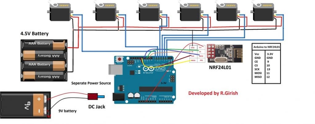
The receiver circuit consists of 6 servo motors, one Arduino and two separate power supply.
The servo motors need higher current to operate so it must not be powered from arduino. That’s why we need two separate power source.
Please apply voltage to servo appropriately; for micro servo motors 4.8V is enough, if you want to power bulkier servo motors, apply voltage matching to the rating of servo.
Please remember that servo motor consumes some power even when there is no moment, that’s because the arm of the servo motor always fight against any change from its commented position.
Program for Receiver:
That concludes the receiver.
How to operate this project:
• Power the both the circuit.
• Now rotate any one of the potentiometer’s knob.
• For example 3rd potentiometer, the corresponding servo at the receiver rotates.
• This applies for all servo motors and potentiometers.
Note: You can connect the transmitter to computer and open serial monitor to see the data such as the angle of the servo motor, voltage level at analog pin and which potentiometer is being currently operated.
If you have any specific question regarding this Arduino based wireless servo motor project, please express in the comment section you may receive a quick response.


Questions & Answers
Hi,
I have no experience with ATTiny85, so I can't suggest you a solution.
Regards
This article was very helpful, but your code will never work. Servos require PWM pins and only pins 3,5,6,9,10 and 11 can be used for servos.
Hi James,
Servo motors will work on any pin, if you use “servo.h” library.
The proposed project is well tested.
Regards
is that this circuit will work as an quad copter
servo motor cannot be used in quadcopter due to weight ratio issue, it has to be BLDC
please suggest me an circuit forvquad copter in low cost
you can explore this page
https://www.homemade-circuits.com/?s=quadcopter
I am very interested in it. Will it work. Do you tested it.
I want to use motor in one of the channel. Can I ?
yes that’s possible…
Can I use arduino nano?
sorry, I am not sure about it…most probably you can use it…
What about its range?
Hi, just want to check with you.
is it possible to add on 3 more servo motor?
Because my project require 8 servo motor.
I’ll forward your question to Mr. GR, he will reply you soon
Hi Yew,
Yes 8 servo is possible but not with Arduino Uno. You need Arduino Mega and also nessary changes in the code.
Regards
Hi
I’m apologize for asking again since my project condition does not mention properly before.
I’m using Arduino Mega to control 8 servo motors with 8 analogue sensors independently through nRF24L01 transceiver.
Is it possible to achieve this condition with using one address?
Hi yew,
Yes it is possible.
We will try to update the code.
Regards
Hi
good afternoon and good day
i would like to ask about where can I download the suitable nRF24L01 transceiver library?
Hi, please try the below link, and let me know if it is OK
https://www.homemade-circuits.com/rf24/
Hi,
I have a question regarding Arduino project.
Can I replace the potentialmeter with flex sensor and add on a accelerometer?
Hi, you can perhaps try it with the help of the instructions provided in the following article:
https://www.homemade-circuits.com/how-flex-resistors-work/
Thank You
Thanks for your project ….but why the servo motor moves slowly … does not move with the potentiometer
sorry I cannot troubleshoot an Arduino, because I am not an expert with Arduino
please.. can you check my code because this section( radio.openReadingPipe(0, address))do not work with my old version arduino program …i changed to this(radio.openReadingPipe(0,0xF0F0F0F0);)but when work the servo motor moves slowly,,, does not move with the potentiometer..it have any solve?
I am sorry I cannot check, however you can refer this link to Arduino.cc forums and ask them about the question, they will surely help you out with the solution