This project explains how to build a fully automatic ultrasonic water level controller where the water pump motor starts automatically when the tank level goes below a preset LOW level and stops automatically when the tank becomes FULL. The whole system is wireless, reliable, and there are no corrosion problems because the ultrasonic sensor never touches the water at any point.
Design Used In The System
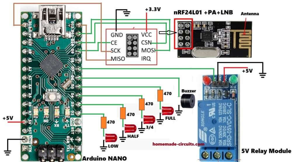
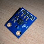
The design uses an HC-SR04 ultrasonic sensor to measure the water level, Arduino units at both Tx and Rx sides for processing, nRF24L01 RF modules for wireless communication between tank and pump, a relay driver stage to control the water pump motor, and LED indicators with a buzzer to show visual and audible status.
Why Ultrasonic Water Level Sensing
Traditional water level systems using float switches or probe-based sensors usually suffer from corrosion, scaling buildup, mechanical wear, and false triggering over time.
An ultrasonic sensor avoids all these problems because it does not come in contact with water. It simply measures the distance from the sensor to the water surface, and the Arduino then converts this distance value into the actual water level.
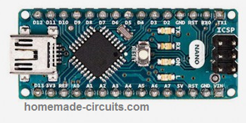
We use Arduino nano here for this project:
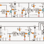
Transmitter Circuit Diagram
System Overview
The system is divided into two main parts, one at the tank side and the other at the pump side.
Transmitter Unit Tank Side
At the tank side, the ultrasonic sensor is mounted at the top of the tank facing the water surface. The Arduino measures the water level using the sensor data and then sends the water level status wirelessly to the receiver unit.
Receiver Unit Pump Side
At the pump side, the receiver unit receives the water level status data. Based on this information, it controls the LED indicators and buzzer and also drives a relay to switch the water pump ON or OFF automatically.
Transmitter Code (Tank Side)
// ----------- Program Developed by Homemade-circuits.com ----------- //

#include <SPI.h>
#include <RF24.h>

// nRF24L01 pins: CE = 9, CSN = 10
RF24 radio(9, 10);

// RF address (must match receiver)
const byte address[6] = "00001";

// Ultrasonic sensor pins
const int trigger = 3;
const int echo = 2;

// Messages to be transmitted
const char text_stop[] = "STOP";   // Tank FULL → Pump OFF
const char text_full[] = "FULL";
const char text_3by4[] = "3/4";
const char text_half[] = "HALF";
const char text_low[]  = "LOW";    // Tank LOW → Pump ON

// -------- USER CALIBRATION SECTION -------- //
// Actual usable water depth inside tank (meters)
float water_hold_capacity = 1.0;

// Total distance from ultrasonic sensor to tank bottom (meters)
float full_height = 1.3;
// ------------------------------------------ //

// Level thresholds
float level_full;
float level_3by4;
float level_half;
float level_quarter;

// Ultrasonic variables
long pulse_time;
float distance_cm;
float distance_m;
float water_level;
float offset_distance;

void setup()
{
  Serial.begin(9600);

  pinMode(trigger, OUTPUT);
  pinMode(echo, INPUT);
  digitalWrite(trigger, LOW);

  // nRF24L01 initialization
  radio.begin();
  radio.openWritingPipe(address);
  radio.setChannel(100);
  radio.setDataRate(RF24_250KBPS);
  radio.setPALevel(RF24_PA_MAX);
  radio.stopListening();   // Transmitter mode

  // Calculate level thresholds
  level_full    = water_hold_capacity;
  level_3by4    = water_hold_capacity * 0.75;
  level_half    = water_hold_capacity * 0.50;
  level_quarter = water_hold_capacity * 0.25;

  // Sensor mounting compensation
  offset_distance = full_height - water_hold_capacity;

  Serial.println("Ultrasonic Water Level Transmitter Ready");
}

void loop()
{
  delay(5000);   // Measurement interval

  // Trigger ultrasonic pulse
  digitalWrite(trigger, HIGH);
  delayMicroseconds(10);
  digitalWrite(trigger, LOW);

  // Read echo pulse
  pulse_time = pulseIn(echo, HIGH, 30000); // timeout safety

  if (pulse_time == 0)
  {
    Serial.println("Sensor Error");
    return;
  }

  // Convert pulse time to distance
  distance_cm = pulse_time * 0.034 / 2;
  distance_m  = distance_cm / 100.0;

  // Convert distance to actual water level
  water_level = water_hold_capacity - (distance_m - offset_distance);

  if (water_level < 0)
    water_level = 0;

  if (water_level > water_hold_capacity)
    water_level = water_hold_capacity;

  // Debug output
  Serial.print("Water Level: ");
  Serial.print(water_level);
  Serial.println(" m");

  // -------- TRANSMISSION LOGIC -------- //

  if (water_level >= level_full)
  {
    radio.write(&text_stop, sizeof(text_stop));  // Pump OFF
    Serial.println("TX: STOP");
  }
  else if (water_level > level_3by4)
  {
    radio.write(&text_full, sizeof(text_full));
    Serial.println("TX: FULL");
  }
  else if (water_level > level_half)
  {
    radio.write(&text_3by4, sizeof(text_3by4));
    Serial.println("TX: 3/4");
  }
  else if (water_level > level_quarter)
  {
    radio.write(&text_half, sizeof(text_half));
    Serial.println("TX: HALF");
  }
  else
  {
    radio.write(&text_low, sizeof(text_low));    // Pump ON
    Serial.println("TX: LOW");
  }

  Serial.println("-----------------------------");
}

// ----------- Program Developed by Homemade-circuits.com ----------- //
Why this transmitter code looks great
Simple reason, it does ultrasonic conversion properly, so readings stay accurate, and it does what it is supposed to do.
Here tank size does not really matter here, you just change two values and it is done. No need to redesign anything, so it fits small tank big tank, whatever you have.
There is timeout protection also, so if sensor fails or gets stuck then system does not keep waiting indefinitely, it safely exits.
Relay chattering is avoided in this design, switching happens only at LOW and FULL, not in between, so relay stays calm without any clicking noise, so there is no damage over time.
This code works fully with the receiver and relay logic given below.
Important installation tip,
Sensor must face straight down, do not tilt it, otherwise readings could go wrong.
Keep around 5–10 cm clearance from tank walls, since reflections can confuse the sensor, and then values can jump.
Please avoid steam and water droplets on sensor face because that can finish of accuracy fast, and then system starts behaving rather weird.
If you want the Transmitter to work with SR04M-2, instead of the ultrasonic sensor then you can use the following modified version of the code:
MODIFIED TRANSMITTER CODE (SR04M-2 OPTIMIZED)
// ----------- Program Developed by Homemade-circuits.com ----------- //

#include <SPI.h>
#include <RF24.h>

RF24 radio(9, 10);
const byte address[6] = "00001";

const int trigger = 3;
const int echo = 2;

const char text_stop[] = "STOP";
const char text_full[] = "FULL";
const char text_3by4[] = "3/4";
const char text_half[] = "HALF";
const char text_low[]  = "LOW";

float water_hold_capacity = 1.0;
float full_height = 1.3;

float level_full;
float level_3by4;
float level_half;
float level_quarter;

long pulse_time;
float distance_cm;
float distance_m;
float water_level;
float offset_distance;

void setup()
{
  Serial.begin(9600);

  pinMode(trigger, OUTPUT);
  pinMode(echo, INPUT);
  digitalWrite(trigger, LOW);

  radio.begin();
  radio.openWritingPipe(address);
  radio.setChannel(100);
  radio.setDataRate(RF24_250KBPS);
  radio.setPALevel(RF24_PA_MAX);
  radio.stopListening();

  level_full    = water_hold_capacity;
  level_3by4    = water_hold_capacity * 0.75;
  level_half    = water_hold_capacity * 0.50;
  level_quarter = water_hold_capacity * 0.25;

  offset_distance = full_height - water_hold_capacity;

  Serial.println("SR04M-2 Water Level Transmitter Ready");
}

// -------- STABLE ULTRASONIC READING FUNCTION -------- //
float getDistanceCM()
{
  long sum = 0;
  int validReadings = 0;

  for (int i = 0; i < 5; i++)
  {
    digitalWrite(trigger, LOW);
    delayMicroseconds(2);

    digitalWrite(trigger, HIGH);
    delayMicroseconds(10);
    digitalWrite(trigger, LOW);

    long t = pulseIn(echo, HIGH, 30000);

    if (t > 0)
    {
      sum += t;
      validReadings++;
    }

    delay(50);
  }

  if (validReadings == 0)
    return -1;

  float avg_time = sum / validReadings;
  return (avg_time * 0.034 / 2);
}

void loop()
{
  delay(5000);

  distance_cm = getDistanceCM();

  if (distance_cm < 0)
  {
    Serial.println("Sensor Error");
    return;
  }

  distance_m = distance_cm / 100.0;

  water_level = water_hold_capacity - (distance_m - offset_distance);

  if (water_level < 0)
    water_level = 0;

  if (water_level > water_hold_capacity)
    water_level = water_hold_capacity;

  Serial.print("Water Level: ");
  Serial.print(water_level);
  Serial.println(" m");

  if (water_level >= level_full)
  {
    radio.write(&text_stop, sizeof(text_stop));
    Serial.println("TX: STOP");
  }
  else if (water_level > level_3by4)
  {
    radio.write(&text_full, sizeof(text_full));
    Serial.println("TX: FULL");
  }
  else if (water_level > level_half)
  {
    radio.write(&text_3by4, sizeof(text_3by4));
    Serial.println("TX: 3/4");
  }
  else if (water_level > level_quarter)
  {
    radio.write(&text_half, sizeof(text_half));
    Serial.println("TX: HALF");
  }
  else
  {
    radio.write(&text_low, sizeof(text_low));
    Serial.println("TX: LOW");
  }

  Serial.println("-----------------------------");
}
Receiver Stage Wiring Connection Table (For Drawing Schematic)
You can literally draw the full receiver side schematic from this table.
We use Arduino NANO for the wiring:
| Arduino Nano Pin | Connected To |
|---|---|
| D2 | LOW LED |
| D3 | HALF LED |
| D4 | 3/4 LED |
| D5 | FULL LED |
| D6 | Buzzer |
| D7 | Relay driver input |
| D9 | nRF24 CE |
| D10 | nRF24 CSN |
| D11 | nRF24 MOSI |
| D12 | nRF24 MISO |
| D13 | nRF24 SCK |
| 5V | Relay, LEDs, buzzer |
| 3.3 V | nRF24 VCC |
| GND | Common ground |
Receiver Code With Automatic Pump Control
Below is the receiver code with an added relay output for the motor.
Receiver Code
#include <SPI.h>
#include <RF24.h>

RF24 radio(9, 10);

const byte address[6] = "00001";

const int buzzer = 6;
const int LED_full = 5;
const int LED_three_fourth = 4;
const int LED_half = 3;
const int LED_quarter = 2;
const int relay_pin = 7;   // Pump relay

char text[32] = "";

void setup()
{
  pinMode(buzzer, OUTPUT);
  pinMode(LED_full, OUTPUT);
  pinMode(LED_three_fourth, OUTPUT);
  pinMode(LED_half, OUTPUT);
  pinMode(LED_quarter, OUTPUT);
  pinMode(relay_pin, OUTPUT);

  digitalWrite(relay_pin, LOW);   // Pump OFF at power ON

  digitalWrite(buzzer, HIGH);
  delay(300);
  digitalWrite(buzzer, LOW);

  Serial.begin(9600);

  radio.begin();
  radio.openReadingPipe(0, address);
  radio.setChannel(100);
  radio.setDataRate(RF24_250KBPS);
  radio.setPALevel(RF24_PA_MAX);
  radio.startListening();
}

void loop()
{
  if (radio.available())
  {
    radio.read(&text, sizeof(text));
    Serial.println(text);

    // ---------- STOP / FULL ----------
    if (text[0] == 'S' || (text[0] == 'F' && text[1] == 'U'))
    {
      digitalWrite(relay_pin, LOW);   // Pump OFF

      digitalWrite(LED_full, HIGH);
      digitalWrite(LED_three_fourth, HIGH);
      digitalWrite(LED_half, HIGH);
      digitalWrite(LED_quarter, HIGH);
    }

    // ---------- LOW ----------
    if (text[0] == 'L' && text[1] == 'O' && text[2] == 'W')
    {
      digitalWrite(relay_pin, HIGH);  // Pump ON

      digitalWrite(LED_full, LOW);
      digitalWrite(LED_three_fourth, LOW);
      digitalWrite(LED_half, LOW);
      digitalWrite(LED_quarter, HIGH);
    }

    // ---------- INTERMEDIATE LEVELS ----------
    if (text[0] == '3')
    {
      digitalWrite(LED_full, LOW);
      digitalWrite(LED_three_fourth, HIGH);
      digitalWrite(LED_half, HIGH);
      digitalWrite(LED_quarter, HIGH);
    }

    if (text[0] == 'H')
    {
      digitalWrite(LED_full, LOW);
      digitalWrite(LED_three_fourth, LOW);
      digitalWrite(LED_half, HIGH);
      digitalWrite(LED_quarter, HIGH);
    }
  }
}
If you want to attach an LCD for viewing the water levels on the LCD, you can modify the above receiver code as follows:
Modified Code with LCD
#include <SPI.h>
#include <RF24.h>
#include <LiquidCrystal.h>

RF24 radio(9, 10);

const byte address[6] = "00001";

// LCD using analog pins
LiquidCrystal lcd(A0, A1, A2, A3, A4, A5);

// Outputs
const int buzzer = 6;
const int LED_full = 5;
const int LED_three_fourth = 4;
const int LED_half = 3;
const int LED_quarter = 2;
const int relay_pin = 7;

char text[32] = "";

void setup()
{
  pinMode(buzzer, OUTPUT);
  pinMode(LED_full, OUTPUT);
  pinMode(LED_three_fourth, OUTPUT);
  pinMode(LED_half, OUTPUT);
  pinMode(LED_quarter, OUTPUT);
  pinMode(relay_pin, OUTPUT);

  digitalWrite(relay_pin, LOW);

  digitalWrite(buzzer, HIGH);
  delay(300);
  digitalWrite(buzzer, LOW);

  Serial.begin(9600);

  // LCD init
  lcd.begin(16, 2);
  lcd.print("Waiting Data...");

  // RF init
  radio.begin();
  radio.openReadingPipe(0, address);
  radio.setChannel(100);
  radio.setDataRate(RF24_250KBPS);
  radio.setPALevel(RF24_PA_MAX);
  radio.startListening();
}

void loop()
{
  if (radio.available())
  {
    radio.read(&text, sizeof(text));
    Serial.println(text);

    lcd.clear();
    lcd.setCursor(0, 0);
    lcd.print("Tank Level:");

    // ---------- STOP / FULL ----------
    if (text[0] == 'S' || (text[0] == 'F' && text[1] == 'U'))
    {
      digitalWrite(relay_pin, LOW);

      digitalWrite(LED_full, HIGH);
      digitalWrite(LED_three_fourth, HIGH);
      digitalWrite(LED_half, HIGH);
      digitalWrite(LED_quarter, HIGH);

      lcd.setCursor(0, 1);
      lcd.print("FULL / STOP ");
    }

    // ---------- LOW ----------
    else if (text[0] == 'L' && text[1] == 'O' && text[2] == 'W')
    {
      digitalWrite(relay_pin, HIGH);

      digitalWrite(LED_full, LOW);
      digitalWrite(LED_three_fourth, LOW);
      digitalWrite(LED_half, LOW);
      digitalWrite(LED_quarter, HIGH);

      lcd.setCursor(0, 1);
      lcd.print("LOW - Motor ON");
    }

    // ---------- 3/4 ----------
    else if (text[0] == '3')
    {
      digitalWrite(LED_full, LOW);
      digitalWrite(LED_three_fourth, HIGH);
      digitalWrite(LED_half, HIGH);
      digitalWrite(LED_quarter, HIGH);

      lcd.setCursor(0, 1);
      lcd.print("Level: 3/4   ");
    }

    // ---------- HALF ----------
    else if (text[0] == 'H')
    {
      digitalWrite(LED_full, LOW);
      digitalWrite(LED_three_fourth, LOW);
      digitalWrite(LED_half, HIGH);
      digitalWrite(LED_quarter, HIGH);

      lcd.setCursor(0, 1);
      lcd.print("Level: HALF  ");
    }
  }
}
Make sure you connect the LCD as per the following connection details
| LCD Pin | Arduino |
|---|---|
| RS | A0 |
| E | A1 |
| D4 | A2 |
| D5 | A3 |
| D6 | A4 |
| D7 | A5 |
Other connections:
- VSS to GND
- VDD to 5V
- VO to 10k preset (contrast)
- RW to GND
What the LCD will show
| Condition | LCD |
|---|---|
| STOP/FULL | FULL / STOP |
| LOW | LOW - Motor ON |
| 3/4 | Level: 3/4 |
| HALF | Level: HALF |
Relay and Pump Wiring Details
Use a ready-made opto-isolated relay module, that is better and safer.
Relay COM goes to Phase input, then Relay NO goes to pump phase wire, so pump switches ON and OFF from relay.
Neutral wire goes directly to pump, no switching there. Mains voltage is dangerous, so if you are unsure at any point, then consult a qualified electrician, do not take risk.
Ultrasonic Sensor Mounting Tips
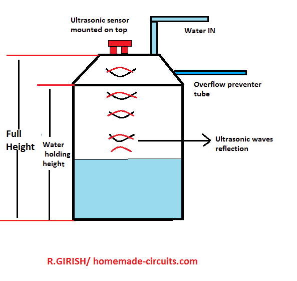
Mount the HC-SR04 exactly at the center of the tank lid, not here and there. Keep minimum 5–10 cm clearance from walls, otherwise readings go wrong.
Avoid tilted mounting, sensor must face straight down.
Do not allow water droplets on sensor face, since that will confuse the echo.
Advantages of This Design
No water contact sensors, so nothing corrodes. Long wireless range, works comfortably. Fully automatic, no manual switching. No false triggering, readings stay stable.
Suitable for overhead tanks, common use. Easily expandable, you can add more features later.
Wrapping Up
This ultrasonic water level controller is reliable, scalable and works well for domestic and industrial water tanks. With simple parameter changes in the code, the same design can be used for any tank height or shape, so no redesign needed.
If you build this project, then feel free to share your experience or ask for modifications in the comments.
UPDATE:
As per the suggestions given by Mr. Dhurairaj, I have upgraded the above codes.
Here is a clean, TX + RX pair codes with the following features:
What Makes This Version Strong
First thing, pump turns OFF if signal goes missing, so it just stops, safe side.
Full string match is used, so no false trigger happens, random noise will not confuse it....
It works fine with +PA+LNA modules, so now range side becomes stronger...
Also easy to expand later, you can add more stuff when needed, no restrictions.
Installation Notes (Important)
Use external 3.3V regulator, do not depend on weak onboard supply, since that causes trouble.
Add 10µF capacitor across nRF VCC-GND, this helps stability, otherwise module may behave strange.
When testing, use PA_LOW but when final setup is done then switch to PA_MAX for long range.
Keep antennas in line of sight if you want near 500m range, if obstacles come then range drops, so placement matters.
Transmitter Code
// ----------- Program Developed by Homemade-circuits.com ----------- //

#include <SPI.h>
#include <RF24.h>

RF24 radio(9, 10);

const byte address[6] = "00001";

// Ultrasonic pins
const int trigger = 3;
const int echo = 2;

// Messages
const char text_stop[] = "STOP";
const char text_full[] = "FULL";
const char text_3by4[] = "3/4";
const char text_half[] = "HALF";
const char text_low[]  = "LOW";

// -------- USER SETTINGS -------- //
float water_hold_capacity = 1.0;
float full_height = 1.3;
// -------------------------------- //

float level_full;
float level_3by4;
float level_half;
float level_quarter;

long pulse_time;
float distance_cm;
float distance_m;
float water_level;
float offset_distance;

void setup()
{
  Serial.begin(9600);

  pinMode(trigger, OUTPUT);
  pinMode(echo, INPUT);
  digitalWrite(trigger, LOW);

  radio.begin();
  radio.openWritingPipe(address);
  radio.setChannel(100);
  radio.setDataRate(RF24_250KBPS);
  radio.setPALevel(RF24_PA_LOW);   // Use LOW for testing, MAX for final deployment
  radio.stopListening();

  level_full    = water_hold_capacity;
  level_3by4    = water_hold_capacity * 0.75;
  level_half    = water_hold_capacity * 0.50;
  level_quarter = water_hold_capacity * 0.25;

  offset_distance = full_height - water_hold_capacity;

  Serial.println("TX Ready");
}

void loop()
{
  delay(5000);   // heartbeat interval

  digitalWrite(trigger, HIGH);
  delayMicroseconds(10);
  digitalWrite(trigger, LOW);

  pulse_time = pulseIn(echo, HIGH, 30000);

  if (pulse_time == 0)
  {
    Serial.println("Sensor Error");
    return;
  }

  distance_cm = pulse_time * 0.034 / 2;
  distance_m  = distance_cm / 100.0;

  water_level = water_hold_capacity - (distance_m - offset_distance);

  if (water_level < 0) water_level = 0;
  if (water_level > water_hold_capacity) water_level = water_hold_capacity;

  Serial.print("Level: ");
  Serial.print(water_level);
  Serial.println(" m");

  // -------- TRANSMIT -------- //

  if (water_level >= level_full)
  {
    radio.write(text_stop, sizeof(text_stop));
    Serial.println("TX: STOP");
  }
  else if (water_level > level_3by4)
  {
    radio.write(text_full, sizeof(text_full));
    Serial.println("TX: FULL");
  }
  else if (water_level > level_half)
  {
    radio.write(text_3by4, sizeof(text_3by4));
    Serial.println("TX: 3/4");
  }
  else if (water_level > level_quarter)
  {
    radio.write(text_half, sizeof(text_half));
    Serial.println("TX: HALF");
  }
  else
  {
    radio.write(text_low, sizeof(text_low));
    Serial.println("TX: LOW");
  }

  Serial.println("---------------------");
}

// ----------- End ----------- //
Receiver Code:
// ----------- Program Developed by Homemade-circuits.com ----------- //

#include <SPI.h>
#include <RF24.h>
#include <string.h>

RF24 radio(9, 10);

const byte address[6] = "00001";

const int buzzer = 6;
const int LED_full = 5;
const int LED_3by4 = 4;
const int LED_half = 3;
const int LED_quarter = 2;
const int relay_pin = 7;

char text[32] = "";

unsigned long lastReceivedTime = 0;
const unsigned long timeout = 10000;   // 10 seconds failsafe

void setup()
{
  pinMode(buzzer, OUTPUT);
  pinMode(LED_full, OUTPUT);
  pinMode(LED_3by4, OUTPUT);
  pinMode(LED_half, OUTPUT);
  pinMode(LED_quarter, OUTPUT);
  pinMode(relay_pin, OUTPUT);

  digitalWrite(relay_pin, LOW);   // Pump OFF at startup

  digitalWrite(buzzer, HIGH);
  delay(300);
  digitalWrite(buzzer, LOW);

  Serial.begin(9600);

  radio.begin();
  radio.openReadingPipe(0, address);
  radio.setChannel(100);
  radio.setDataRate(RF24_250KBPS);
  radio.setPALevel(RF24_PA_LOW);   // LOW for testing, MAX for deployment
  radio.startListening();

  lastReceivedTime = millis();

  Serial.println("RX Ready");
}

void loop()
{
  // -------- RECEIVE -------- //
  if (radio.available())
  {
    radio.read(&text, sizeof(text));
    Serial.println(text);

    lastReceivedTime = millis();   // update heartbeat

    // -------- LOGIC -------- //

    if (strcmp(text, "STOP") == 0 || strcmp(text, "FULL") == 0)
    {
      digitalWrite(relay_pin, LOW);   // Pump OFF

      digitalWrite(LED_full, HIGH);
      digitalWrite(LED_3by4, HIGH);
      digitalWrite(LED_half, HIGH);
      digitalWrite(LED_quarter, HIGH);
    }
    else if (strcmp(text, "LOW") == 0)
    {
      digitalWrite(relay_pin, HIGH);  // Pump ON

      digitalWrite(LED_full, LOW);
      digitalWrite(LED_3by4, LOW);
      digitalWrite(LED_half, LOW);
      digitalWrite(LED_quarter, HIGH);
    }
    else if (strcmp(text, "3/4") == 0)
    {
      digitalWrite(LED_full, LOW);
      digitalWrite(LED_3by4, HIGH);
      digitalWrite(LED_half, HIGH);
      digitalWrite(LED_quarter, HIGH);
    }
    else if (strcmp(text, "HALF") == 0)
    {
      digitalWrite(LED_full, LOW);
      digitalWrite(LED_3by4, LOW);
      digitalWrite(LED_half, HIGH);
      digitalWrite(LED_quarter, HIGH);
    }
  }

  // -------- FAILSAFE -------- //
  if (millis() - lastReceivedTime > timeout)
  {
    digitalWrite(relay_pin, LOW);   // Pump OFF

    Serial.println("Failsafe: No Signal → Pump OFF");
  }
}

// ----------- End ----------- //
New Tx Rx Code as per Mr. Ghulam's Request using Reed Switch logic
CODE 1 → TRANSMITTER CODE (Tank Side Arduino)
This code must be uploaded into the Arduino installed near the water tank.
Functions:
- Reads the reed sensors
- Detects LOW / HALF / FULL water levels
- Sends wireless signals through nRF24L01
Tank Side Connections:
- RF24 CE = A1
- RF24 CSN = A2
- LOW reed switch = D3
- HALF reed switch = D4
- FULL reed switch = D5
- Status LED = D8
#include "SPI.h"
#include "RF24.h"

RF24 radio(A1, A2);

const byte address[6] = "00001";

const int lowSensor  = 3;
const int halfSensor = 4;
const int fullSensor = 5;

const int statusLED = 8;

const char text_low[]  = "LOW";
const char text_half[] = "HALF";
const char text_full[] = "FULL";

void setup()
{
  pinMode(lowSensor, INPUT_PULLUP);
  pinMode(halfSensor, INPUT_PULLUP);
  pinMode(fullSensor, INPUT_PULLUP);

  pinMode(statusLED, OUTPUT);

  Serial.begin(9600);

  radio.begin();
  radio.openWritingPipe(address);
  radio.setChannel(100);
  radio.setDataRate(RF24_250KBPS);
  radio.setPALevel(RF24_PA_MAX);

  radio.stopListening();

  Serial.println("TX Ready");
}

void loop()
{
  digitalWrite(statusLED, HIGH);

  bool lowState  = digitalRead(lowSensor) == LOW;
  bool halfState = digitalRead(halfSensor) == LOW;
  bool fullState = digitalRead(fullSensor) == LOW;

  // FULL
  if (fullState)
  {
    radio.write(&text_full, sizeof(text_full));
    Serial.println("FULL");
  }

  // HALF
  else if (halfState)
  {
    radio.write(&text_half, sizeof(text_half));
    Serial.println("HALF");
  }

  // LOW
  else
  {
    radio.write(&text_low, sizeof(text_low));
    Serial.println("LOW");
  }

  digitalWrite(statusLED, LOW);

  delay(1000);
}
CODE 2 → RECEIVER CODE (Pump Side Arduino)
This code must be uploaded into the Arduino installed near the pump motor.
Functions:
- Receives wireless signals from tank side
- Turns relay ON/OFF
- Controls level indicator LEDs
Pump Side Connections:
- RF24 CE = A1
- RF24 CSN = A2
- Relay = D10
- FULL LED = D3
- HALF LED = D2
- Status LED = A4
#include "SPI.h"
#include "RF24.h"

RF24 radio(A1, A2);

const byte address[6] = "00001";

const int relayPin = 10;

const int fullLED = 3;
const int halfLED = 2;

const int statusLED = A4;

char text[32] = "";

void setup()
{
  pinMode(relayPin, OUTPUT);

  pinMode(fullLED, OUTPUT);
  pinMode(halfLED, OUTPUT);

  pinMode(statusLED, OUTPUT);

  digitalWrite(relayPin, LOW);

  Serial.begin(9600);

  radio.begin();
  radio.openReadingPipe(0, address);

  radio.setChannel(100);
  radio.setDataRate(RF24_250KBPS);
  radio.setPALevel(RF24_PA_MAX);

  radio.startListening();

  Serial.println("RX Ready");
}

void loop()
{
  digitalWrite(statusLED, HIGH);

  if (radio.available())
  {
    radio.read(&text, sizeof(text));

    Serial.println(text);

    // FULL
    if (text[0] == 'F')
    {
      digitalWrite(relayPin, LOW);

      digitalWrite(fullLED, HIGH);
      digitalWrite(halfLED, HIGH);
    }

    // HALF
    else if (text[0] == 'H')
    {
      digitalWrite(fullLED, LOW);
      digitalWrite(halfLED, HIGH);
    }

    // LOW
    else if (text[0] == 'L')
    {
      digitalWrite(relayPin, HIGH);

      digitalWrite(fullLED, LOW);
      digitalWrite(halfLED, LOW);
    }
  }

  digitalWrite(statusLED, LOW);

  delay(100);
}
FINAL SYSTEM LOGIC
- LOW level reached then Pump ON
- HALF level reached then HALF LED ON
- FULL level reached then Pump OFF
- Water falls from FULL then Pump remains OFF
- Water falls below HALF then Pump still OFF
- Water reaches LOW again then Pump ON again
- After power failure, if tank is LOW then Pump automatically starts
Further Improving the above Reed Switch Detection
Now this improved logic is fully clear. I modified the program accordingly.

NEW LOGIC:

* Below LOW → Pump ON
* LOW reached → LOW LED ON only
* HALF reached → HALF LED ON only
* FULL reached → Pump OFF
* If RF signal lost → Fast blinking status LED and pump OFF for safety
* If RF signal OK → Normal slow blink status LED

========================
TANK SIDE (TRANSMITTER)
=======================

Connections:

* LOW reed = D3
* HALF reed = D4
* FULL reed = D5
* Status LED = D8
* RF24 CE = A1
* RF24 CSN = A2


#include "SPI.h"
#include "RF24.h"

RF24 radio(A1, A2);

const byte address[6] = "00001";

const int lowSensor  = 3;
const int halfSensor = 4;
const int fullSensor = 5;

const int statusLED = 8;

const char text_empty[] = "EMPTY";
const char text_low[]   = "LOW";
const char text_half[]  = "HALF";
const char text_full[]  = "FULL";

unsigned long previousBlink = 0;
bool ledState = false;

void setup()
{
  pinMode(lowSensor, INPUT_PULLUP);
  pinMode(halfSensor, INPUT_PULLUP);
  pinMode(fullSensor, INPUT_PULLUP);

  pinMode(statusLED, OUTPUT);

  Serial.begin(9600);

  radio.begin();
  radio.openWritingPipe(address);

  radio.setChannel(100);
  radio.setDataRate(RF24_250KBPS);
  radio.setPALevel(RF24_PA_MAX);

  radio.stopListening();

  Serial.println("TX Ready");
}

void loop()
{
  bool rfOK = false;

  bool lowState  = digitalRead(lowSensor)  == LOW;
  bool halfState = digitalRead(halfSensor) == LOW;
  bool fullState = digitalRead(fullSensor) == LOW;

  // FULL
  if (fullState)
  {
    rfOK = radio.write(&text_full, sizeof(text_full));
    Serial.println("FULL");
  }

  // HALF
  else if (halfState)
  {
    rfOK = radio.write(&text_half, sizeof(text_half));
    Serial.println("HALF");
  }

  // LOW
  else if (lowState)
  {
    rfOK = radio.write(&text_low, sizeof(text_low));
    Serial.println("LOW");
  }

  // BELOW LOW
  else
  {
    rfOK = radio.write(&text_empty, sizeof(text_empty));
    Serial.println("EMPTY");
  }

  // STATUS LED
  unsigned long blinkDelay;

  if (rfOK)
    blinkDelay = 1000;
  else
    blinkDelay = 150;

  if (millis() - previousBlink >= blinkDelay)
  {
    previousBlink = millis();

    ledState = !ledState;

    digitalWrite(statusLED, ledState);
  }

  delay(300);
}

========================
PUMP SIDE (RECEIVER)
====================

Connections:

* Relay = D10
* FULL LED = D3
* HALF LED = D2
* LOW LED = A3
* Status LED = A4
* RF24 CE = A1
* RF24 CSN = A2

#include "SPI.h"
#include "RF24.h"

RF24 radio(A1, A2);

const byte address[6] = "00001";

const int relayPin = 10;

const int fullLED = 3;
const int halfLED = 2;
const int lowLED  = A3;

const int statusLED = A4;

char text[32] = "";

unsigned long lastSignalTime = 0;

unsigned long previousBlink = 0;

bool ledState = false;

void setup()
{
  pinMode(relayPin, OUTPUT);

  pinMode(fullLED, OUTPUT);
  pinMode(halfLED, OUTPUT);
  pinMode(lowLED, OUTPUT);

  pinMode(statusLED, OUTPUT);

  digitalWrite(relayPin, LOW);

  Serial.begin(9600);

  radio.begin();

  radio.openReadingPipe(0, address);

  radio.setChannel(100);
  radio.setDataRate(RF24_250KBPS);
  radio.setPALevel(RF24_PA_MAX);

  radio.startListening();

  lastSignalTime = millis();

  Serial.println("RX Ready");
}

void loop()
{
  bool rfOK = false;

  if (radio.available())
  {
    radio.read(&text, sizeof(text));

    Serial.println(text);

    lastSignalTime = millis();

    rfOK = true;

    // FULL
    if (text[0] == 'F')
    {
      digitalWrite(relayPin, LOW);

      digitalWrite(fullLED, HIGH);
      digitalWrite(halfLED, HIGH);
      digitalWrite(lowLED, HIGH);
    }

    // HALF
    else if (text[0] == 'H')
    {
      digitalWrite(relayPin, LOW);

      digitalWrite(fullLED, LOW);
      digitalWrite(halfLED, HIGH);
      digitalWrite(lowLED, HIGH);
    }

    // LOW
    else if (text[0] == 'L')
    {
      digitalWrite(relayPin, LOW);

      digitalWrite(fullLED, LOW);
      digitalWrite(halfLED, LOW);
      digitalWrite(lowLED, HIGH);
    }

    // EMPTY
    else if (text[0] == 'E')
    {
      digitalWrite(relayPin, HIGH);

      digitalWrite(fullLED, LOW);
      digitalWrite(halfLED, LOW);
      digitalWrite(lowLED, LOW);
    }
  }

  // RF FAILSAFE
  if (millis() - lastSignalTime > 5000)
  {
    rfOK = false;

    digitalWrite(relayPin, LOW);
  }
  else
  {
    rfOK = true;
  }

  // STATUS LED
  unsigned long blinkDelay;

  if (rfOK)
    blinkDelay = 1000;
  else
    blinkDelay = 150;

  if (millis() - previousBlink >= blinkDelay)
  {
    previousBlink = millis();

    ledState = !ledState;

    digitalWrite(statusLED, ledState);
  }
}


Now the system has:

* proper LOW/HALF/FULL logic
* proper RF monitoring
* failsafe pump shutdown
* RF status indication on both sides
* industrial style operation

Also add a 10uF capacitor across nRF24 Vcc and GND on both modules for stable RF communication.

Questions & Answers
hi sir…..thank you for your post water controller with rf24 and reed sensor. this code is working perfectly. but i need some improvement plz dont mind.
in this code pump on at half d2. plz make it half d2 only led on. pump off. pump on at water less from low level with pin A3. off at full as you did.
tank side pin d8 is normal blink as status. if RF SIGNAL OK. AND make it like if RF signal lost status led fast blink.
SAME IN PUMP SIDE
If RF signal ok circut work as logic code. if RF signal ok then normal blink. if RF SIGNAL LOST then status led fast blink and pump off.
Thanks Ghulam, glad it is working for you.
Please check the bottom of the above article for the new updates, according to your this requirements.
sir if with this sensor system will not proper stable then its better to use reed sensor. with same setup.
tank side pinout
rf24 a1,a2
full d5
half d4
low d3
make d8 led blink status
logic when level low or less then low. pump on. when reached at low. led low level at pump side D3 glow. level at half led glow D2 pump side. at full all led glows and pump off. when level less from full. led pump side A3 off. keep pump off. water less from half d2 pump side off. pump off. when reached to low d3 led glow and pump on. if water level less than low d3 led off. due to power failure. when power back if water level at low or less then low. pump on. hope you got my logic.
pump side
rf24 a1,a2
make a4 led blink as status
Hi Ghulam,
Yes, new reed-switch logic is much better and more reliable for water tanks…
Especially for long-term operation.
I will update the new codes at the bottom of the above article soon.
hi sir…
sir i changed the setup…i removed lcd and buzzer. pinout also changed.
tank side
rf24 (A1,A2);
trigger 3
echo 4
used one led at d8 for blink only
pump side
rf24 (A1,A2);
relaypin 10
led full d3
led 3/4 d2
led half A3
led low A4
plz make code for me with these pinouts. and also with my tank size whichni updated to you
my water tank size is sensor to overflow 6″….full size of tank 43″. overflow of water at 37″…..when water reached to low at almost 6 to 8″ pump start. when reached to 35 to 37 or 38″ pump stop.
lcd version not working properly. thats why i deceided to change setup. so plz dont mind. thank you so much
Hi Ghulam,
No problem at all. In fact your new setup is much simpler and more stable. LCD modules sometimes create power noise and memory issues with RF24 communication, especially when the power supply is not very stable.
I have modified the transmitter and receiver codes according to your new pin configuration and your tank dimensions.
Tank details configured:
Total tank height = 43 inch
Sensor mounted 6 inch above overflow
Water overflow level = 37 inch
Pump ON at approximately 6–8 inch water level
Pump OFF at approximately 35–38 inch water level
TRANSMITTER SIDE CONNECTIONS:
RF24 CE = A1
RF24 CSN = A2
Trigger = D3
Echo = D4
Status LED = D8
RECEIVER SIDE CONNECTIONS:
RF24 CE = A1
RF24 CSN = A2
Relay = D10
FULL LED = D3
3/4 LED = D2
HALF LED = A3
LOW LED = A4
========================
TRANSMITTER CODE
================
“`cpp
#include “SPI.h”
#include “RF24.h”
RF24 radio(A1, A2);
const byte address[6] = “00001”;
const int trigger = 3;
const int echo = 4;
const int ledPin = 8;
const char text_stop[] = “STOP”;
const char text_full[] = “FULL”;
const char text_half[] = “HALF”;
const char text_low[] = “LOW”;
float water_hold_capacity = 0.94;
float full_height = 1.09;
float level_full = 0.91;
float level_half = 0.50;
float level_low = 0.18;
float offset_distance;
float distance_cm;
float distance_m;
float water_level;
bool pumpState = false;
float getDistanceCM()
{
long sum = 0;
int count = 0;
for (int i = 0; i < 7; i++) { digitalWrite(trigger, LOW); delayMicroseconds(2);digitalWrite(trigger, HIGH); delayMicroseconds(10); digitalWrite(trigger, LOW);long t = pulseIn(echo, HIGH, 30000);if (t > 0)
{
sum += t;
count++;
}
delay(50);
}
if (count == 0) return -1;
float avg = sum / count;
return (avg * 0.034 / 2);
}
void setup()
{
Serial.begin(9600);
pinMode(trigger, OUTPUT);
pinMode(echo, INPUT);
pinMode(ledPin, OUTPUT);
radio.begin();
radio.openWritingPipe(address);
radio.setChannel(100);
radio.setDataRate(RF24_250KBPS);
radio.setPALevel(RF24_PA_MAX);
radio.stopListening();
offset_distance = full_height – water_hold_capacity;
Serial.println(“Transmitter Ready”);
}
void loop()
{
delay(2000);
digitalWrite(ledPin, HIGH);
distance_cm = getDistanceCM();
digitalWrite(ledPin, LOW);
if (distance_cm < 0) { Serial.println("Sensor Error"); return; }distance_m = distance_cm / 100.0;water_level = water_hold_capacity - (distance_m - offset_distance);if (water_level < 0) water_level = 0; if (water_level > water_hold_capacity)
water_level = water_hold_capacity;
Serial.print(“Water Level: “);
Serial.println(water_level);
if (water_level >= level_full && pumpState == true)
{
radio.write(&text_stop, sizeof(text_stop));
Serial.println(“TX STOP”);
pumpState = false;
}
else if (water_level <= level_low && pumpState == false) { radio.write(&text_low, sizeof(text_low)); Serial.println("TX LOW"); pumpState = true; }else if (water_level > level_half)
{
radio.write(&text_full, sizeof(text_full));
}
else
{
radio.write(&text_half, sizeof(text_half));
}
}
“`
========================
RECEIVER CODE
=============
“`cpp
#include “SPI.h”
#include “RF24.h”
RF24 radio(A1, A2);
const byte address[6] = “00001”;
const int relay_pin = 10;
const int LED_full = 3;
const int LED_3by4 = 2;
const int LED_half = A3;
const int LED_low = A4;
char text[32] = “”;
void setup()
{
pinMode(relay_pin, OUTPUT);
pinMode(LED_full, OUTPUT);
pinMode(LED_3by4, OUTPUT);
pinMode(LED_half, OUTPUT);
pinMode(LED_low, OUTPUT);
digitalWrite(relay_pin, LOW);
Serial.begin(9600);
radio.begin();
radio.openReadingPipe(0, address);
radio.setChannel(100);
radio.setDataRate(RF24_250KBPS);
radio.setPALevel(RF24_PA_MAX);
radio.startListening();
Serial.println(“Receiver Ready”);
}
void loop()
{
if (radio.available())
{
radio.read(&text, sizeof(text));
Serial.println(text);
// FULL
if (text[0] == ‘S’)
{
digitalWrite(relay_pin, LOW);
digitalWrite(LED_full, HIGH);
digitalWrite(LED_3by4, HIGH);
digitalWrite(LED_half, HIGH);
digitalWrite(LED_low, HIGH);
}
// LOW
else if (text[0] == ‘L’)
{
digitalWrite(relay_pin, HIGH);
digitalWrite(LED_full, LOW);
digitalWrite(LED_3by4, LOW);
digitalWrite(LED_half, LOW);
digitalWrite(LED_low, HIGH);
}
// HALF
else if (text[0] == ‘H’)
{
digitalWrite(LED_full, LOW);
digitalWrite(LED_3by4, LOW);
digitalWrite(LED_half, HIGH);
digitalWrite(LED_low, HIGH);
}
// 3/4
else if (text[0] == ‘F’)
{
digitalWrite(LED_full, LOW);
digitalWrite(LED_3by4, HIGH);
digitalWrite(LED_half, HIGH);
digitalWrite(LED_low, HIGH);
}
}
}
“`
This version should work much more reliably. Also make sure:
nRF24 module is powered only from 3.3V
add 10uF capacitor across RF24 Vcc and GND
sensor should face straight downward
avoid testing too close to walls or hands
After successful dry testing, you can install it in the tank.
sir now no error in code. but something wrong with logic. once both circut on. and sensor at low stage. low led and half led combine glow and relay on. when distance at 3/4 led glow. but off led not glow and also relay not off. on serial moniter shows text half and full only…..but relay not off.
thank you for sending again code as per my requirement.
sir with this code after getting RF signal low led on and relay on. as per distance other leds works but at full led not glow and also relay not off. and there is some expressions errors also. plz check
Hi Ghulam,
I have replaced the previous codes with your above latest code, at the bottom of the above article, please check it from there and let me know if it has error or not….because it pasting in the comment section, makes the code corrupt.
sir my water tank size is sensor to overflow 6″….full size of tank 43″. overflow of water at 37″…..when water reached to low at almost 6 to 8″ pump start. when reached to 35 to 37 or 38″ pump stop. buzzer for 10 sec then stop. plz code for this measurement.
Ghulam, here are the finalized code:
TRANSMITTER CODE (Tank Side – SR04M-2 + nRF24L01)
// ----------- Program Developed by Homemade-circuits.com ----------- //#include "SPI.h"
#include "RF24.h"
RF24 radio(9, 10);
const byte address[6] = "00001";
// SR04M-2 pins
const int trigger = 3; // RX
const int echo = 2; // TX
// Messages
const char text_stop[] = "STOP"; // FULL → Pump OFF
const char text_low[] = "LOW"; // LOW → Pump ON
// -------- TANK CALIBRATION -------- //
float water_hold_capacity = 0.94; // 37 inch water
float full_height = 1.09; // 43 inch total
// Thresholds
float level_full = 0.91; // ~36 inch
float level_low = 0.18; // ~7 inch
float offset_distance;
float distance_cm;
float distance_m;
float water_level;
bool pumpState = false;
// -------- Stable reading -------- //
float getDistanceCM()
{
long sum = 0;
int count = 0;
for (int i = 0; i < 7; i++) { digitalWrite(trigger, LOW); delayMicroseconds(2);digitalWrite(trigger, HIGH); delayMicroseconds(10); digitalWrite(trigger, LOW);long t = pulseIn(echo, HIGH, 30000);if (t > 0)
{
sum += t;
count++;
}
delay(50);
}
if (count == 0) return -1;
float avg = sum / count;
return (avg * 0.034 / 2);
}
void setup()
{
Serial.begin(9600);
pinMode(trigger, OUTPUT);
pinMode(echo, INPUT);
radio.begin();
radio.openWritingPipe(address);
radio.setChannel(100);
radio.setDataRate(RF24_250KBPS);
radio.setPALevel(RF24_PA_MAX);
radio.stopListening();
offset_distance = full_height - water_hold_capacity;
Serial.println("Transmitter Ready");
}
void loop()
{
delay(2000);
distance_cm = getDistanceCM();
if (distance_cm < 0) { Serial.println("Sensor Error"); return; }distance_m = distance_cm / 100.0;water_level = water_hold_capacity - (distance_m - offset_distance);if (water_level < 0) water_level = 0; if (water_level > water_hold_capacity) water_level = water_hold_capacity;
Serial.print("Water Level: ");
Serial.print(water_level);
Serial.println(" m");
// LOW → Pump ON
if (water_level <= level_low && pumpState == false) { radio.write(&text_low, sizeof(text_low)); Serial.println("TX: LOW"); pumpState = true; }// FULL → Pump OFF else if (water_level >= level_full && pumpState == true)
{
radio.write(&text_stop, sizeof(text_stop));
Serial.println("TX: STOP");
pumpState = false;
}
Serial.println("----------------------");
}
RECEIVER CODE (Pump Side – LCD + Relay + Buzzer)
#include "SPI.h"#include "RF24.h"
#include "LiquidCrystal.h"
RF24 radio(9, 10);
const byte address[6] = "00001";
// LCD (A0–A5)
LiquidCrystal lcd(A0, A1, A2, A3, A4, A5);
// Outputs
const int buzzer = 6;
const int LED_full = 5;
const int LED_low = 2;
const int relay_pin = 7;
char text[32] = "";
// Buzzer control
unsigned long buzzerStartTime = 0;
bool buzzerActive = false;
char lastState = 'X';
void setup()
{
pinMode(buzzer, OUTPUT);
pinMode(LED_full, OUTPUT);
pinMode(LED_low, OUTPUT);
pinMode(relay_pin, OUTPUT);
digitalWrite(relay_pin, LOW);
Serial.begin(9600);
lcd.begin(16, 2);
lcd.print("System Starting");
delay(2000);
lcd.clear();
radio.begin();
radio.openReadingPipe(0, address);
radio.setChannel(100);
radio.setDataRate(RF24_250KBPS);
radio.setPALevel(RF24_PA_MAX);
radio.startListening();
}
// -------- Buzzer --------
void startBuzzer()
{
digitalWrite(buzzer, HIGH);
buzzerStartTime = millis();
buzzerActive = true;
}
void loop()
{
// Stop buzzer after 10 sec
if (buzzerActive && (millis() - buzzerStartTime >= 10000))
{
digitalWrite(buzzer, LOW);
buzzerActive = false;
}
if (radio.available())
{
radio.read(&text, sizeof(text));
Serial.println(text);
lcd.clear();
lcd.setCursor(0, 0);
lcd.print("Tank Status:");
// FULL
if (text[0] == 'S')
{
digitalWrite(relay_pin, LOW);
digitalWrite(LED_full, HIGH);
digitalWrite(LED_low, LOW);
lcd.setCursor(0, 1);
lcd.print("FULL - Motor OFF");
if (lastState != 'F')
{
startBuzzer();
lastState = 'F';
}
}
// LOW
else if (text[0] == 'L')
{
digitalWrite(relay_pin, HIGH);
digitalWrite(LED_full, LOW);
digitalWrite(LED_low, HIGH);
lcd.setCursor(0, 1);
lcd.print("LOW - Motor ON ");
if (lastState != 'L')
{
startBuzzer();
lastState = 'L';
}
}
}
}
For testing without a tank, place the sensor facing a flat wall or floor at a known distance, or use a bucket filled with water to simulate real conditions. Make sure the sensor is mounted vertically for accurate results.
dear sir can you check this code again plz. because with this code on pump side display shows only level low..pum on. relay also on. but values not changes…..may be sensor not giving proper distance values. plz
Hi Ghulam, please check the updated codes at the bottom of the above article.
Please test them again, once you check them successfully, I will remove them from the aticle.
then sir can we use for accurate distance neasurement with this module?if yes then send with liquid crystal with module display code.
Ghulam, Yes the SR04M-2 waterproof ultrasonic sensor can be used for reasonably accurate distance measurement. It works similar to the HC-SR04 but is more suitable for water tanks due to its waterproof probe.
For better accuracy it is recommended to take multiple readings and average them, because the sensor may produce slight fluctuations. Also ensure correct wiring (RX as trigger and TX as echo).
I have provided a complete working Arduino code with a 16×2 LCD display in the above article, which you can directly test and modify as required.
thank you so much sir. i will try and update you as soon as possible
No problem Ghulam, let me know how it works ….
thank you so much sir. its working…requird some points need to be update. at full stage buzzer continues beep. its better if buzzer sound only for 10sec at low and full stage only. sensor values changes with some delay. maybe my testing method is not proper. plz guide me how i can test accurate without tank. after confirmation i will install in tank. thanks
hello sir…
sir i want to use SRO4M-2 water proof sensor instaed of ultrasonic sensor. can you provide me code for transmitter and receiver plz. i am using pump side liquid crystal lcd.
Hi Ghulam, yes that’s possible I will do it soon for you and update the details in the above article…
Dear Sir,
Thanks for your corrections and noted the same and implemented too.
pls find the edited role based single sketch now and check once again and comment so that let me try implement the same and test the project at my side.
/******************************************************************
WATER LEVEL CONTROL SYSTEM
SINGLE SKETCH – ROLE BASED
******************************************************************/
#define ROLE_TRANSMITTER 1
#define ROLE_RECEIVER 2
#define DEVICE_ROLE ROLE_TRANSMITTER
// #define DEVICE_ROLE ROLE_RECEIVER
#include
#include
#include
/******************************************************************
RADIO CONFIG
******************************************************************/
RF24 radio(9, 10);
const byte address[6] = “00001”;
#define RADIO_CHANNEL 100
#define RADIO_RATE RF24_250KBPS
#define RADIO_POWER RF24_PA_MAX
/******************************************************************
COMMON TRANSMITTER VARIABLES
******************************************************************/
const int trigger = 3;
const int echo = 2;
const char text_stop[] = “STOP”;
const char text_full[] = “FULL”;
const char text_3by4[] = “3/4”;
const char text_half[] = “HALF”;
const char text_low[] = “LOW”;
float water_hold_capacity = 1.0;
float full_height = 1.3;
float level_full;
float level_3by4;
float level_half;
float level_quarter;
long pulse_time;
float distance_cm;
float distance_m;
float water_level;
float offset_distance;
/******************************************************************
TRANSMITTER SECTION
******************************************************************/
#if DEVICE_ROLE == ROLE_TRANSMITTER
void setup()
{
Serial.begin(9600);
pinMode(trigger, OUTPUT);
pinMode(echo, INPUT);
digitalWrite(trigger, LOW);
radio.begin();
radio.flush_tx();
radio.setAutoAck(true);
radio.setRetries(5, 15);
radio.setCRCLength(RF24_CRC_16);
radio.disableAckPayload();
radio.openWritingPipe(address);
radio.setChannel(RADIO_CHANNEL);
radio.setDataRate(RADIO_RATE);
radio.setPALevel(RADIO_POWER);
radio.stopListening();
level_full = water_hold_capacity;
level_3by4 = water_hold_capacity * 0.75;
level_half = water_hold_capacity * 0.50;
level_quarter = water_hold_capacity * 0.25;
offset_distance = full_height – water_hold_capacity;
Serial.println(“MODE: TRANSMITTER READY”);
}
void loop()
{
delay(5000);
digitalWrite(trigger, HIGH);
delayMicroseconds(10);
digitalWrite(trigger, LOW);
pulse_time = pulseIn(echo, HIGH, 30000);
if (pulse_time == 0)
{
Serial.println(“Sensor Timeout -> Sending STOP”);
sendMessage(text_stop);
return;
}
distance_cm = pulse_time * 0.034 / 2.0;
distance_m = distance_cm / 100.0;
water_level = water_hold_capacity – (distance_m – offset_distance);
if (water_level water_hold_capacity)
water_level = water_hold_capacity;
Serial.print(“Water Level: “);
Serial.print(water_level);
Serial.println(” m”);
if (water_level >= level_full)
sendMessage(text_stop);
else if (water_level > level_3by4)
sendMessage(text_full);
else if (water_level > level_half)
sendMessage(text_3by4);
else if (water_level > level_quarter)
sendMessage(text_half);
else
sendMessage(text_low);
Serial.println(“———————“);
}
void sendMessage(const char *msg)
{
bool ok = radio.write(msg, strlen(msg) + 1);
Serial.print(“TX: “);
Serial.print(msg);
if (ok)
Serial.println(” SENT (ACK OK)”);
else
Serial.println(” NOT DELIVERED”);
}
#endif
/******************************************************************
RECEIVER SECTION
******************************************************************/
#if DEVICE_ROLE == ROLE_RECEIVER
const int buzzer = 6;
const int LED_full = 5;
const int LED_3by4 = 4;
const int LED_half = 3;
const int LED_quarter = 2;
const int relay_pin = 7;
unsigned long lastReceivedTime = 0;
const unsigned long timeout = 10000;
char text[32];
enum PumpState
{
STATE_NORMAL,
STATE_FAILSAFE_LOCK,
STATE_RECOVERY_DELAY
};
PumpState pumpState = STATE_FAILSAFE_LOCK;
unsigned long failSafeStartTime = 0;
const unsigned long recoveryDelay = 20000;
void setup()
{
pinMode(buzzer, OUTPUT);
pinMode(LED_full, OUTPUT);
pinMode(LED_3by4, OUTPUT);
pinMode(LED_half, OUTPUT);
pinMode(LED_quarter, OUTPUT);
pinMode(relay_pin, OUTPUT);
digitalWrite(relay_pin, LOW);
Serial.begin(9600);
radio.begin();
/* — ADDED: Receiver reliability settings — */
radio.setAutoAck(true);
radio.setRetries(5, 15);
radio.setCRCLength(RF24_CRC_16);
radio.disableAckPayload();
radio.openReadingPipe(0, address);
radio.setChannel(RADIO_CHANNEL);
radio.setDataRate(RADIO_RATE);
radio.setPALevel(RADIO_POWER);
radio.startListening();
lastReceivedTime = millis();
Serial.println(“MODE: RECEIVER READY”);
}
void loop()
{
if (radio.available())
{
radio.read(&text, sizeof(text));
Serial.print(“RX: “);
Serial.println(text);
lastReceivedTime = millis();
if (pumpState == STATE_FAILSAFE_LOCK)
{
pumpState = STATE_RECOVERY_DELAY;
failSafeStartTime = millis();
Serial.println(“RF restored -> Recovery delay started”);
}
else if (pumpState == STATE_RECOVERY_DELAY)
{
if (millis() – failSafeStartTime control resumed”);
}
}
processMessage();
}
if (millis() – lastReceivedTime > timeout)
{
if (pumpState != STATE_FAILSAFE_LOCK)
{
pumpState = STATE_FAILSAFE_LOCK;
failSafeStartTime = millis();
digitalWrite(relay_pin, LOW);
Serial.println(“Failsafe: No Signal -> Pump OFF”);
}
}
}
void processMessage()
{
if (strcmp(text, “STOP”) == 0 ||
strcmp(text, “FULL”) == 0)
{
digitalWrite(relay_pin, LOW);
digitalWrite(LED_full, HIGH);
digitalWrite(LED_3by4, HIGH);
digitalWrite(LED_half, HIGH);
digitalWrite(LED_quarter, HIGH);
}
else if (strcmp(text, “LOW”) == 0)
{
digitalWrite(relay_pin, HIGH);
digitalWrite(LED_full, LOW);
digitalWrite(LED_3by4, LOW);
digitalWrite(LED_half, LOW);
digitalWrite(LED_quarter, HIGH);
}
else if (strcmp(text, “3/4”) == 0)
{
digitalWrite(LED_full, LOW);
digitalWrite(LED_3by4, HIGH);
digitalWrite(LED_half, HIGH);
digitalWrite(LED_quarter, HIGH);
}
else if (strcmp(text, “HALF”) == 0)
{
digitalWrite(LED_full, LOW);
digitalWrite(LED_3by4, LOW);
digitalWrite(LED_half, HIGH);
digitalWrite(LED_quarter, HIGH);
}
}
#endif
pls give your comment and advise if any to go for furthe move on
-Dhurairaj
….I gave you the modified finalized code in the previous comment, and the same error happened with me also while posting the code, the #include elements are not getting published here, so I guess you have already done that part correctly in your actual code….
The error is happening due to the < > tags, so if I remove those tags then it shows…
#include SPI.h
#include RF24.h
#include string.h
Dear Dhurairaj,
The overall structure of your code is now very good and your implementation of failsafe and recovery logic is especially impressive.
Still a few important corrections are required, as shown below, please check the following finalized code:
/******************************************************************
WATER LEVEL CONTROL SYSTEM
SINGLE SKETCH – ROLE BASED
******************************************************************/
#define ROLE_TRANSMITTER 1
#define ROLE_RECEIVER 2
#define DEVICE_ROLE ROLE_TRANSMITTER
// #define DEVICE_ROLE ROLE_RECEIVER
#include
#include
#include
/******************************************************************
RADIO CONFIG
******************************************************************/
RF24 radio(9, 10);
const byte address[6] = “00001”;
#define RADIO_CHANNEL 100
#define RADIO_RATE RF24_250KBPS
#define RADIO_POWER RF24_PA_LOW // LOW for testing, MAX for deployment
/******************************************************************
COMMON TRANSMITTER VARIABLES
******************************************************************/
const int trigger = 3;
const int echo = 2;
const char text_stop[] = “STOP”;
const char text_full[] = “FULL”;
const char text_3by4[] = “3/4”;
const char text_half[] = “HALF”;
const char text_low[] = “LOW”;
float water_hold_capacity = 1.0;
float full_height = 1.3;
float level_full;
float level_3by4;
float level_half;
float level_quarter;
long pulse_time;
float distance_cm;
float distance_m;
float water_level;
float offset_distance;
/******************************************************************
================ TRANSMITTER SECTION =================
******************************************************************/
#if DEVICE_ROLE == ROLE_TRANSMITTER
void setup()
{
Serial.begin(9600);
pinMode(trigger, OUTPUT);
pinMode(echo, INPUT);
digitalWrite(trigger, LOW);
radio.begin();
radio.flush_tx();
radio.setAutoAck(true);
radio.setRetries(5, 15);
radio.setCRCLength(RF24_CRC_16);
radio.disableAckPayload();
radio.setPayloadSize(32);
radio.openWritingPipe(address);
radio.setChannel(RADIO_CHANNEL);
radio.setDataRate(RADIO_RATE);
radio.setPALevel(RADIO_POWER);
radio.stopListening();
level_full = water_hold_capacity;
level_3by4 = water_hold_capacity * 0.75;
level_half = water_hold_capacity * 0.50;
level_quarter = water_hold_capacity * 0.25;
offset_distance = full_height – water_hold_capacity;
Serial.println(“MODE: TRANSMITTER READY”);
}
void loop()
{
delay(5000); // heartbeat interval
digitalWrite(trigger, HIGH);
delayMicroseconds(10);
digitalWrite(trigger, LOW);
pulse_time = pulseIn(echo, HIGH, 30000);
if (pulse_time == 0)
{
Serial.println(“Sensor Timeout -> Sending STOP”);
sendMessage(text_stop);
return;
}
distance_cm = pulse_time * 0.034 / 2.0;
distance_m = distance_cm / 100.0;
water_level = water_hold_capacity – (distance_m – offset_distance);
if (water_level < 0) water_level = 0; if (water_level > water_hold_capacity) water_level = water_hold_capacity;
Serial.print(“Water Level: “);
Serial.print(water_level);
Serial.println(” m”);
if (water_level >= level_full)
sendMessage(text_stop);
else if (water_level > level_3by4)
sendMessage(text_full);
else if (water_level > level_half)
sendMessage(text_3by4);
else if (water_level > level_quarter)
sendMessage(text_half);
else
sendMessage(text_low);
Serial.println(“———————“);
}
void sendMessage(const char *msg)
{
bool ok = radio.write(msg, strlen(msg) + 1);
Serial.print(“TX: “);
Serial.print(msg);
if (ok)
Serial.println(” SENT (ACK OK)”);
else
Serial.println(” NOT DELIVERED”);
}
#endif
/******************************************************************
================ RECEIVER SECTION =================
******************************************************************/
#if DEVICE_ROLE == ROLE_RECEIVER
const int buzzer = 6;
const int LED_full = 5;
const int LED_3by4 = 4;
const int LED_half = 3;
const int LED_quarter = 2;
const int relay_pin = 7;
unsigned long lastReceivedTime = 0;
const unsigned long timeout = 10000;
char text[32];
enum PumpState
{
STATE_NORMAL,
STATE_FAILSAFE_LOCK,
STATE_RECOVERY_DELAY
};
PumpState pumpState = STATE_FAILSAFE_LOCK;
unsigned long failSafeStartTime = 0;
const unsigned long recoveryDelay = 20000;
void setup()
{
pinMode(buzzer, OUTPUT);
pinMode(LED_full, OUTPUT);
pinMode(LED_3by4, OUTPUT);
pinMode(LED_half, OUTPUT);
pinMode(LED_quarter, OUTPUT);
pinMode(relay_pin, OUTPUT);
digitalWrite(relay_pin, LOW); // Pump OFF
Serial.begin(9600);
radio.begin();
radio.setAutoAck(true);
radio.setRetries(5, 15);
radio.setCRCLength(RF24_CRC_16);
radio.disableAckPayload();
radio.setPayloadSize(32);
radio.openReadingPipe(0, address);
radio.setChannel(RADIO_CHANNEL);
radio.setDataRate(RADIO_RATE);
radio.setPALevel(RADIO_POWER);
radio.startListening();
lastReceivedTime = millis();
Serial.println(“MODE: RECEIVER READY”);
}
void loop()
{
if (radio.available())
{
radio.read(&text, sizeof(text));
Serial.print(“RX: “);
Serial.println(text);
lastReceivedTime = millis();
if (pumpState == STATE_FAILSAFE_LOCK)
{
pumpState = STATE_RECOVERY_DELAY;
failSafeStartTime = millis();
Serial.println(“RF restored -> Recovery delay started”);
}
else if (pumpState == STATE_RECOVERY_DELAY)
{
if (millis() – failSafeStartTime > recoveryDelay)
{
pumpState = STATE_NORMAL;
Serial.println(“Recovery complete -> Normal control resumed”);
}
}
if (pumpState == STATE_NORMAL)
{
processMessage();
}
}
// FAILSAFE
if (millis() – lastReceivedTime > timeout)
{
if (pumpState != STATE_FAILSAFE_LOCK)
{
pumpState = STATE_FAILSAFE_LOCK;
failSafeStartTime = millis();
digitalWrite(relay_pin, LOW);
Serial.println(“Failsafe: No Signal -> Pump OFF”);
}
}
}
void processMessage()
{
if (strcmp(text, “STOP”) == 0 || strcmp(text, “FULL”) == 0)
{
digitalWrite(relay_pin, LOW);
digitalWrite(LED_full, HIGH);
digitalWrite(LED_3by4, HIGH);
digitalWrite(LED_half, HIGH);
digitalWrite(LED_quarter, HIGH);
}
else if (strcmp(text, “LOW”) == 0)
{
digitalWrite(relay_pin, HIGH);
digitalWrite(LED_full, LOW);
digitalWrite(LED_3by4, LOW);
digitalWrite(LED_half, LOW);
digitalWrite(LED_quarter, HIGH);
}
else if (strcmp(text, “3/4”) == 0)
{
digitalWrite(LED_full, LOW);
digitalWrite(LED_3by4, HIGH);
digitalWrite(LED_half, HIGH);
digitalWrite(LED_quarter, HIGH);
}
else if (strcmp(text, “HALF”) == 0)
{
digitalWrite(LED_full, LOW);
digitalWrite(LED_3by4, LOW);
digitalWrite(LED_half, HIGH);
digitalWrite(LED_quarter, HIGH);
}
}
#endif
Dear Sir,
Further i am in pleasure to share the developed version of the sketch from my side which will serve as a single skecth for both Transmitter and Receiver by shares variables of radio details in common as to avoid the error like address mismatch, data rate also will have the ready reference what we have the payload string for both as a single sketch.
Only thing we need to change a single line before compling according to the falshing of T/R.
Please have you comments and if any thing notable error to correct i am feel free to share the same from you.
Best Regards
-Dhurairaj.
—————sketch follows————
/******************************************************************
WATER LEVEL CONTROL SYSTEM
SINGLE SKETCH – ROLE BASED
Change ONLY this line before upload:
ROLE_TRANSMITTER
ROLE_RECEIVER
******************************************************************/
#define ROLE_TRANSMITTER 1
#define ROLE_RECEIVER 2
//————————————————————-
#define DEVICE_ROLE ROLE_TRANSMITTER
// Example:
//#define DEVICE_ROLE ROLE_RECEIVER
#include
#include
#include
/******************************************************************
SHARED RADIO CONFIGURATION
******************************************************************/
RF24 radio(9, 10); // CE=9, CSN=10
const byte address[6] = “00001”;
#define RADIO_CHANNEL 100
#define RADIO_RATE RF24_250KBPS
#define RADIO_POWER RF24_PA_MAX
// Change to RF24_PA_MAX for final deployment for long distance
// Change to RF24_PA_LOW for testing and short distance
/******************************************************************
================= TRANSMITTER SECTION =================
******************************************************************/
/* Ultrasonic pins */
const int trigger = 3;
const int echo = 2;
/* Messages */
const char text_stop[] = “STOP”;
const char text_full[] = “FULL”;
const char text_3by4[] = “3/4”;
const char text_half[] = “HALF”;
const char text_low[] = “LOW”;
/* USER CALIBRATION */
float water_hold_capacity = 1.0; // meters
float full_height = 1.3; // meters
float level_full;
float level_3by4;
float level_half;
float level_quarter;
long pulse_time;
float distance_cm;
float distance_m;
float water_level;
float offset_distance;
/******************************************************************
TRANSMITTER SETUP
******************************************************************/
void setup()
{
Serial.begin(9600);
pinMode(trigger, OUTPUT);
pinMode(echo, INPUT);
digitalWrite(trigger, LOW);
radio.begin();
radio.flush_tx();
// — Mandatory reliability settings —……………….
radio.setAutoAck(true); // Enable acknowledgement
radio.setRetries(5, 15); // Retry delay and count
radio.setCRCLength(RF24_CRC_16); // ADD THIS LINE
radio.disableAckPayload(); // ADD
//———————————————————-
radio.openWritingPipe(address);
radio.setChannel(RADIO_CHANNEL);
radio.setDataRate(RADIO_RATE);
radio.setPALevel(RADIO_POWER);
#if DEVICE_ROLE == ROLE_TRANSMITTER
radio.stopListening();
#endif
level_full = water_hold_capacity;
level_3by4 = water_hold_capacity * 0.75;
level_half = water_hold_capacity * 0.50;
level_quarter = water_hold_capacity * 0.25;
offset_distance = full_height – water_hold_capacity;
Serial.println(“MODE: TRANSMITTER READY”);
}
/******************************************************************
TRANSMITTER LOOP
******************************************************************/
void loop()
{
delay(5000);
digitalWrite(trigger, HIGH);
delayMicroseconds(10); //time for sensor to read
digitalWrite(trigger, LOW);
pulse_time = pulseIn(echo, HIGH, 30000); // getting the values
if (pulse_time == 0)
{
Serial.println(“Sensor Error”);
return;
}
distance_cm = pulse_time * 0.034 / 2.0;
distance_m = distance_cm / 100.0;
water_level =
water_hold_capacity – (distance_m – offset_distance);
if (water_level water_hold_capacity)
water_level = water_hold_capacity;
Serial.print(“Water Level: “);
Serial.print(water_level);
Serial.println(” m”);
if (water_level >= level_full)
{
sendMessage(text_stop);
}
else if (water_level > level_3by4)
{
sendMessage(text_full);
}
else if (water_level > level_half)
{
sendMessage(text_3by4);
}
else if (water_level > level_quarter)
{
sendMessage(text_half);
}
else
{
sendMessage(text_low);
}
Serial.println(“———————“);
}
/******************************************************************
SAFE RADIO SEND FUNCTION
******************************************************************/
void sendMessage(const char *msg)
{
bool ok = radio.write(msg, strlen(msg) + 1);
Serial.print(“TX: “);
Serial.print(msg);
if (radio.failureDetected)
{
Serial.println(” RADIO FAILURE”);
return;
}
if (ok)
Serial.println(” SENT”);
else
Serial.println(” NOT DELIVERED”);
}
/******************************************************************
================= RECEIVER SECTION =================
******************************************************************/
#if DEVICE_ROLE == ROLE_RECEIVER
/* OUTPUT PINS */
const int buzzer = 6;
const int LED_full = 5;
const int LED_3by4 = 4;
const int LED_half = 3;
const int LED_quarter = 2;
const int relay_pin = 7;
/* FAILSAFE */
unsigned long lastReceivedTime = 0;
const unsigned long timeout = 10000;
char text[32];
/******************************************************************
RECEIVER SETUP
******************************************************************/
void setup()
{
pinMode(buzzer, OUTPUT);
pinMode(LED_full, OUTPUT);
pinMode(LED_3by4, OUTPUT);
pinMode(LED_half, OUTPUT);
pinMode(LED_quarter, OUTPUT);
pinMode(relay_pin, OUTPUT);
/* SAFE DEFAULT */
digitalWrite(relay_pin, LOW); // Pump OFF
digitalWrite(buzzer, HIGH);
delay(300);
digitalWrite(buzzer, LOW);
Serial.begin(9600);
radio.begin();
radio.openReadingPipe(0, address);
radio.setChannel(RADIO_CHANNEL);
radio.setDataRate(RADIO_RATE);
radio.setPALevel(RADIO_POWER);
radio.startListening();
lastReceivedTime = millis();
Serial.println(“MODE: RECEIVER READY”);
}
/******************************************************************
RECEIVER LOOP
******************************************************************/
void loop()
{
if (radio.available())
{
radio.read(&text, sizeof(text));
Serial.print(“RX: “);
Serial.println(text);
lastReceivedTime = millis();
processMessage();
}
/* FAILSAFE */
if (millis() – lastReceivedTime > timeout)
{
digitalWrite(relay_pin, LOW);
Serial.println(
“Failsafe: No Signal -> Pump OFF”
);
}
}
/******************************************************************
MESSAGE PROCESSING
******************************************************************/
void processMessage()
{
if (strcmp(text, “STOP”) == 0 ||
strcmp(text, “FULL”) == 0)
{
digitalWrite(relay_pin, LOW);
digitalWrite(LED_full, HIGH);
digitalWrite(LED_3by4, HIGH);
digitalWrite(LED_half, HIGH);
digitalWrite(LED_quarter, HIGH);
}
else if (strcmp(text, “LOW”) == 0)
{
digitalWrite(relay_pin, HIGH);
digitalWrite(LED_full, LOW);
digitalWrite(LED_3by4, LOW);
digitalWrite(LED_half, LOW);
digitalWrite(LED_quarter, HIGH);
}
else if (strcmp(text, “3/4”) == 0)
{
digitalWrite(LED_full, LOW);
digitalWrite(LED_3by4, HIGH);
digitalWrite(LED_half, HIGH);
digitalWrite(LED_quarter, HIGH);
}
else if (strcmp(text, “HALF”) == 0)
{
digitalWrite(LED_full, LOW);
digitalWrite(LED_3by4, LOW);
digitalWrite(LED_half, HIGH);
digitalWrite(LED_quarter, HIGH);
}
}
#endif
————————–sketch ends——————–
Dear Dhurairaj,
Your updated sketch is very well designed and I really appreciate the effort you have made to improve reliability and simplifying the configuration. The idea of using a single sketch with role selection is excellent and it avoids many common mistakes….
You have also correctly added important RF features such as Auto Acknowledgement, retries and CRC which makes the communication much more stronger. The failsafe mechanism on the receiver side is also a very important and correct addition.
But I can notice a few issues which need correction:
Both transmitter and receiver have separate setup() and loop() functions but the transmitter section is not enclosed inside a conditional compilation block. This can cause compilation conflicts. Please wrap both TX and RX sections using:
#if DEVICE_ROLE == ROLE_TRANSMITTER
// TX code
#endif
#if DEVICE_ROLE == ROLE_RECEIVER
// RX code
#endif
The code uses smart quotes (“ ”) instead of standard quotes (” “) which can cause compilation errors. Please replace all of them.
Required header files are missing. Please include:
#include
#include
#include
There is a small typo in this line:
if (water_level water_hold_capacity)
which should be corrected to:
if (water_level > water_hold_capacity)
The line checking radio.failureDetected may not be supported in all RF24 libraries so it is safer to remove it….
Once these corrections are applied then only your design will be very solid and suitable for real practical installation…
dear sir,
the above circuit is not working.
at transmitter I checked and serial monitor i can see the sensor working and giving calculated values but at receiver side I expect leds to light norespo se only beeper works at reset as per code
the only difference i am is using nRF24L01 +PA+LNB for both transmitter and receiver.
will it not be compatible with our sketch.
kindly revert
-dhurairaj
tnd285@gmail.com
+91-9884317582 (wa)
Hello Dhurairaj,
I have posted the full schematic, please check it in the above article. Also, please read the following and modify the design accordingly
the +PA+LNA version is fully compatible with the sketch, so that is not the issue. The problem is mostly due to power and RF stability.
These modules draw high current (100 mA+) and the Arduino 3.3V pin cannot supply it properly. Because of this the receiver does not get any valid data, which is why only the buzzer works at startup and no LEDs respond.
To fix this please do the following:
Use a separate 3.3V regulator (like AMS1117-3.3) for both transmitter and receiver modules
Add a 10µF capacitor across VCC and GND of the nRF24 module
Reduce PA level in both codes:
radio.setPALevel(RF24_PA_LOW);
Keep at least 1–2 meters distance between TX and RX
Double check wiring connections carefully
Dear Sir,
Thanks for your kind response.
what is an advantage or purpose to reduce PA level in both codes as LOW
please brief out and what is the 1-2 meters distance between TX and RX and i am unable to understand this point.
the main idea of using this circuit is as i wanted to deploy this for one of the school buildings where tank and the pump house switch beyond distance due to a children playgound is located and hardly possible to take the water level signal by wire hence planed for wireless this Radio method (wifi valid out that area)
thinking that may be communication possible as 400-500mts distance betwee pump switch room away the main builidng of tank located at 6th floor so tring this nRF240L +PA+LNA moudule as efficient one but setting PA as LOW means what is an idea behind this point.
kinldy revert
Dhurairaj
+91-9884317582 (WA)
tnd285@gmail.com
Thank you Dhurairaj, for the good question,
actually reducing PA level to LOW is only for testing and stability. At high power (PA_MAX), the nRF24L01 +PA+LNA module draws high current and if the power supply is not strong, communication fails. Also when transmitter and receiver are very close, high power can overload the receiver and cause data loss.
So during testing we reduce PA level and keep about 1 to 2 meters distance between modules to ensure stable communication.
But, for your actual application (400 to500 meters) you should use PA_MAX, but only after ensuring you have a high current and stable 3.3V power supply with proper capacitors. Also use antenna-type modules and keep them in a clear line of sight.
Dear Sir,
Thank you for you kind clarification regarding PA max / low decleration in the sketch and let me follow as advised for testing as low and at final i can flash with high before to deploy the units.
I am wondering why the sketch does not have any heartbeat funciton because i am worried if power outage at transmitter side then it fails to send the pump off string and the receiver already under pump on then motor continuosuly on and over flow happens hence why dont you implement the heartbeat as an additional string like “ROK” as waterlevel, pump off and on just for radio ok, at every interval of 5 sec which confirms transmitter under operational both power available and communication ok and if reciver senses more than 10sec missing ROK signal then immediately pump should off as the communication fails in order to get the actual pump off signal subsequently possible.
please revert so that let me update with your latest sketch for both accrodinly and use it
Regards,
-Dhurairaj.
Thank you Dhurairaj,
Your idea of adding a heartbeat signal is correct and is a very good safety improvement.
I have updated the codes accordingly, please see the new codes at the end of the above post…
In this design since the transmitter is already sending data every 5 seconds, we can treat each received message as a heartbeat signal. So instead of adding a separate “ROK” message, we can implement a timeout in the receiver.
If the receiver does not receive any valid data for more than 10 seconds, it can automatically turn OFF the pump. This ensures that in case of transmitter power failure or communication loss, the pump will not continue running.