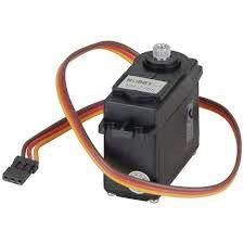
In this project I have explained the basic specifications of a servo motor and also how to control a Servo Motor using a 555 timer IC, and just two push buttons.
WHY SERVO?
Servo Motors are used in variety of fields. These are mainly used as actuators in those areas where we need a precise movement to control output load.
Best example is a RC car. Let's see you want movement of 45 degree, not more not less. In that case you can't use a simple DC motor because it will overshoot the desired position every time you power it up.
And thus we need a Servo Motor to achieve this task as it will not only make a precise 45 degree rotation but will also stop smoothly at the desired position.
FEW TECHNICAL POINTS ONE MUST KNOW:
A) Before buying or using a servo one must know what's inside it and how it works. a servo motor is made up of three key components:
1. A DC motor
2. 1 Potentiometer, either analogue or Digital
3. Control circuit
B) There are total 3 wires that come out of a Servo Motor:
1. RED: To positive of supply
2. BLACK: TO negative of supply
3. ORANGE OR YELLOW: Connected to a reference voltage i.e., a pwm source
C) Servo Motor can rotate 90 degrees in either direction, covering maximum 180 degrees i.e., either 90 degrees clockwise or 90 degree anticlockwise from its neutral position.
To rotate the motor clockwise, on time period of clock pulse must be greater than 1.5 milliseconds and to rotate it anticlockwise on time period must be less than 1.25 milliseconds but frequency should lie between 50 to 60 Hertz.
And thus we are going to use a 555 timer to generate such clock pulses for us.
Servo Motor Controller using Potentiometer

Basic Working And Power Supply
So in this circuit which you can see above, we are using only one Integrated Circuit 555 which is used for generating the Pulse Width Modulation Signal that will drive the Servo Motor.
The circuit is powered with plus 6 volts supply on the left side and 0 volts on the ground side.
Now we can see that Capacitor C1 which has a value of 470 microfarad is connected across the supply.
We use this to smooth the voltage and remove any sudden fluctuation which can disturb the Integrated Circuit 555 or the Servo Motor. So this capacitor helps to keep the supply line clean and steady.
Control Section Using Pin 5
Next we have P1 which is a 10 kiloohm Preset or potentiometer connected to Pin 5 of the Integrated Circuit 555.
We know that Pin 5 is called the Control Voltage Pin. By adjusting the knob of P1, we can change the voltage on this pin and this will change the Pulse Width of the PWM Signal. The Pulse Width finally decides where exactly the Servo Arm will move and hold.
Capacitor C2 which is 100 nanofarad is connected between Pin 5 and Ground which helps to make the control voltage stable while we adjust P1 and also reduces any kind of electrical noise.
Timing Network
Then we have the Timing Network which is made by Resistor R1 of 1 kiloohm, Resistor R2 of 100 kiloohm, and Capacitor C3 of 0.014 microfarad which are all together connected in the standard Astable Mode between Pin 7, Pin 6, Pin 2, and Ground.
This combination will decide the base frequency of the PWM Signal.
For Servo Motor application, we require almost 50 Hz frequency, so this timing network is selected to produce that value.
The Duty Cycle which means the ON Time of the PWM Signal, is controlled through P1. When we change this ON Time, the Servo moves either forward or reverse according to that.
Decoupling And Output Connection
Now we have Capacitor C4 which is 0.1 microfarad connected between Pin 8 and Ground which is mainly for decoupling purpose. It removes high frequency noise that may come into the power pin of the Integrated Circuit 555.
When the Servo Motor moves, then it creates some noise or disturbance in the power line, without this capacitor, the 555 may start giving unstable pulses.
The output is taken from Pin 3 of the Integrated Circuit 555 which is directly connected to the Yellow Wire of the Servo Motor.
The Red Wire of the Servo is connected to plus 6 volts and the Black Wire goes to Ground. The Yellow Signal Wire receives the PWM Output and tells the Servo how much to move.
Servo Movement Explanation
When the ON Time of the pulse is around 1 millisecond, that means less than 1.5 milliseconds, then the Servo rotates fully in one side. When the ON Time is around 2 milliseconds, that means more than 1.5 milliseconds, then the Servo rotates fully in the other side.
With a pulse width around 1.5 milliseconds, the Servo will stay exactly at the center position.
If the pulses are continuously coming then the Servo will hold its torque and position, but if the pulses stop, then the Servo will lose torque and become relaxed.
So to summarize this part, the Integrated Circuit 555 generates a fixed signal of 50 Hz. When we adjust P1, then we vary the width of the PWM pulse which makes the Servo move forward, reverse, or stay at any point between the two limits.
Capacitors C1, C2, and C4 ensure that the supply and the signal remain stable. Resistors R1, R2, and Capacitor C3 decide the timing. So this very simple setup allow us to control the Servo Motor smoothly by hand.
Parts List For Servo Motor Control Using Potentiometer
| Reference | Component Type | Value/Specification | Description/Function |
|---|---|---|---|
| IC1 | IC 555 | NE555 or LM555 | Generates PWM signal |
| R1 | Resistor | 1k | Timing resistor |
| R2 | Resistor | 100k | Timing resistor |
| P1 | Preset (Potentiometer) | 10k | Adjusts PWM duty cycle and servo position |
| C1 | Electrolytic Capacitor | 470uF / 25V | Smooths the power supply |
| C2 | Capacitor | 100nF (0.1uF) | Stabilizes control voltage |
| C3 | Capacitor | 0.014uF | Timing capacitor |
| C4 | Capacitor | 0.1uF | Power supply decoupling |
| Servo Motor | Tower Pro SG90 or equivalent | 5V to 6V | Receives PWM from IC1 pin 3 |
| Power Supply | DC Source | +6V | Powers the circuit and servo motor |
Servo Motor Push Button Control Version
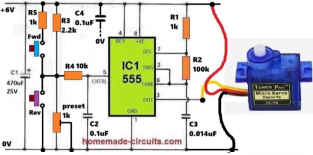
Now let us move to the version where we use Push Buttons to control the Servo Motor instead of the preset.
Again, the Integrated Circuit 555 gives out the PWM Signal from its output Pin 3. The Servo Signal Wire (Yellow) is connected to this Pin 3 while the Red Wire of the Servo takes plus 6 volts and the Black Wire shares the same ground as the 555.
Control Voltage Network
Pin 5 which is the Control Voltage Pin is connected to a small network. In this part we have Resistor R4 of 10 kiloohm connected to Pin 5 and there is a 1 kiloohm Preset connected between Pin 5 and Ground.
This Preset helps us to set the center position of the Servo when no button is pressed.
This means that Pin 5 will receive a middle voltage through this network which will create a pulse width of around 1.5 milliseconds and the Servo arm will stay at the middle.
Forward And Reverse Buttons Working
There are two Push Buttons, one is Forward and the other is Reverse.
When the Forward Button is pressed then Resistor R3 of 2.2 kiloohm and Resistor R5 of 1 kiloohm pull the control voltage slightly higher, which makes the PWM Pulse Width become less than 1.5 milliseconds and the Servo moves in one direction.
When the Reverse Button is pressed, then voltage at Pin 5 goes lower through the preset path which increases the PWM Pulse Width above 1.5 milliseconds.
This causes the Servo to move in the opposite direction.
Noise Filtering And Stability
Capacitor C4 of 0.1 microfarad is connected from the top of R3 to Ground, which helps to filter out the noise and prevent any jitter when no button is pressed.
Another Capacitor C2 of 0.1 microfarad is connected from Pin 5 to Ground to give extra stability to the control voltage. The main timing part remains the same R1 of 1 kiloohm, R2 of 100 kiloohm and C3 of 0.014 microfarad generate around 50 Hz frequency.
Working Sequence
Here is how the operation takes place step by step.
With no button pressed the Pin 5 voltage comes through the preset and R4 and the Servo stays in the center.
When the Forward Button is pressed then Pin 5 voltage rises and the Servo moves in one direction.
When the Reverse Button is pressed, then Pin 5 voltage falls and the Servo moves in the opposite direction.
When both buttons are released then preset voltage comes back automatically and the Servo goes back to its center position again.
Final Thoughts
So you get a simple manual control system which moves the Servo left right using push buttons and also brings it back to center when no button is pressed.
That completes our full explanation on the Simple Servo Motor Controller Circuit using the Integrated Circuit 555. If you have any related question then please put them in the comments and we will be happy to help you.
Parts List For Servo Motor Control Using Push Buttons
| Reference | Component Type | Value/Specification | Description/Function |
|---|---|---|---|
| IC1 | IC 555 | NE555 or LM555 | Generates PWM signal |
| R1 | Resistor | 1k | Timing resistor |
| R2 | Resistor | 100k | Timing resistor |
| R3 | Resistor | 2.2k | Pull-up path for forward control |
| R4 | Resistor | 10k | Control voltage bias resistor |
| R5 | Resistor | 1k | Pull-up path for reverse control |
| Preset | Preset (Potentiometer) | 1k | Adjusts servo center position |
| C1 | Electrolytic Capacitor | 470uF / 25V | Smooths the power supply |
| C2 | Capacitor | 0.1uF | Stabilizes control voltage |
| C3 | Capacitor | 0.014uF | Timing capacitor |
| C4 | Capacitor | 0.1uF | Power supply decoupling and noise filter |
| Push Button (Fwd) | Tactile Switch | SPST | Moves servo forward |
| Push Button (Rev) | Tactile Switch | SPST | Moves servo reverse |
| Servo Motor | Tower Pro SG90 or equivalent | 5V to 6V | Receives PWM from IC1 pin 3 |
| Power Supply | DC Source | +6V | Powers the circuit and servo motor |
Audio/Video Representation
COMPONENTS REQUIRED FOR THIS PROJECT:
Another Simple Servo Motor Controller using IC 555 PWM
The figure above shows how a servo motor can be operated precisely using PWM signals from the IC 555.
The rate of pulses repeated by the circuit can be anything between 20 Hz and 70 Hz. We can vary the positive pulse width from 1 millisecond to 2 milliseconds (ms).
When the PWM is set at 1 ms the servo rotates to one of its extreme positions. When a PWM of 2 ms is given to the motor it rotates to its opposite extreme.
You will servo motors designed to travel 90° or 180 °. PWMs ranging from 1 ms to 2 ms will allow the servo to travel across 90°or 180 ° positions correspondingly.
How the Circuit Works
The design employs a 555 oscillator/timer arranged in an astable mode to produce the correct PWM, in accordance with the adjustment of potentiometer R4.
A normal 555 astable circuit's working frequency and pulse width will vary when the value of one of the timing resistors is adjusted.
Additionally, the proposed 555 pwm controller circuit allows for independent regulation of the duty cycle or pulse/space ratio without changing the frequency.
To accomplish this, two distinct channels are provided for the charging and discharging process of C1.
Capacitor C1 charges as soon as the supply DC is switched ON through R1, D2, and half of R4. When C1 charges to a level of 4V (two-thirds of the supply voltage), the IC 555 output switches state.
This causes pin 7 to go low. With pin7 at low or 0V, capacitor C1 starts discharging via the other half of R4, R3, D1, and R2.
The internal flip-flop of the IC changes state yet again as soon as the voltage across C1 drops to 2 volts.
This causes pin#7 to go high. Due to this the capacitor once again initiates its charging process.
Thus, adjusting R4 modifies the charge and discharge rates in complimentary ways, keeping the total cycle duration and frequency constant.
The circuit works at around 55 Hz and has a roughly 10% duty cycle with the component values as indicated in the diagram. The servo may rotate over its whole range of 180 degrees by adjusting R4 along an arc of 60 degrees.
The user can choose and experimentally discover the potentiometer's position in relation to the servo's motion. The circuit has been built so that the total of R2, R3, and R4 is almost equivalent to 100k. This enables the user to adjust the value of R4 for achieving the desired operating characteristics.
R2 and R3 offer a minimum amount of resistance in the discharge path. This ensures that the circuit is not harmed when R4 is adjusted to minimum.
Servo Motor Tester Circuit
It is quite practical to be able to perform electronic adjustments of a variable speed drive or mechanical adjustment of servo motors without having to use the entire transmitter and receiver set, but simply by using the tester described below. Its implementation presents no difficulty or even adjustment. Moreover, it has been designed from readily available components at a very low cost.
Servo motor control signals
A servo motor includes a stage intended to supply the internal motor with precision. Any rotation of the latter mechanically drives a tiny potentiometer charged with informing the control circuit of the position of the lever (output arm).
The control of a servo motor or a variable speed drive does not rely on a simple logic level or an analog value. In radio control, the signal takes a very specific form. A pulse of variable duration (between 1 ms and 2 ms) must be sent every 20 ms, in other words, at a regular frequency of 50 Hz.
Figure below shows the relationship between the width of the pulse and the effect obtained.
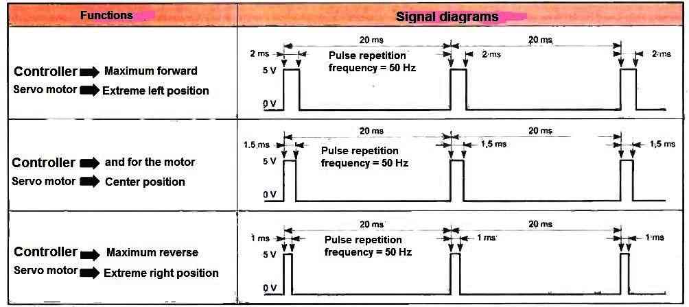
It goes without saying that the indicated direction and rotation sense are arbitrary and depend on the wiring of the motor or the mechanical implementation of the servo motor.
The values between 1 ms and 1.5 ms and between 1.5 ms and 2 ms give a reduced speed in "forward" or "reverse" for a variable speed drive and an intermediate position to the "right" or "left" for a servo motor.
Circuit Description
Figure below clearly distinguishes three stages. The astable oscillator provides a well-stable square wave signal at a frequency of 50 Hz.
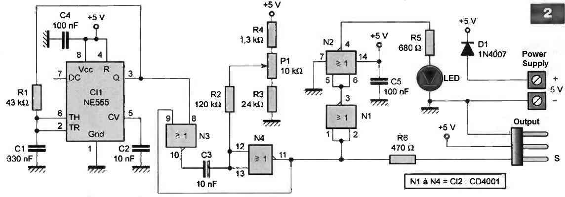
This particular assembly of IC1, an NE555, outputs a 50% duty cycle (the duration at the "high" logic level is equal to that at the "low" level) on pin (3). Resistance R1 and capacitor C1 set the frequency through charge and discharge cycles of C1 through R1 using the approximate formula below:
F = 0.72 (R1 x C1)
where the frequency is expressed in hertz "Hz," R1 in "Megaohm," and C1 in "uF." We obtain the following result:
F = 0.72 (0.043 x 0.33) = 50.73 Hertz
The output of the oscillator (pin 3 of C11) triggers the monostable made up of the N3 and N4 logic gates, which are of the "NOR" type.
Capacitor C3 and potentiometer P1 determine the non-retriggerable monostable duration. Resistors R2, R3, and R4 condition the limits not to be exceeded to obtain a pulse width between 1 ms and 2 ms. It goes without saying that the precision of these delays depends on that of the components used.
Attention! A servo motor, for its preservation, should not work at the maximum of its range, to the right or left (overload of electronics and mechanical forcing).
The output of the monostable controls the servo motor input via protection resistor R6. Observe the standardized fit arrangement on the output connector, with the positive in the center to avoid possible short circuits. The inversion between the ground and the signal does not cause damage.
We have taken advantage of the non-essential logic gates, N1 and N2 of the "NOR" type assembled in an inverter, in order to visualize, with the LED, the proper functioning of the device through a very rapid blinking.
Resistor R5 limits the current flowing in the LED. Diode D1 protects the tester from an accidental inversion of the polarity of the power supply, for example, from a battery pack whose voltage does not exceed 5.5 V.


Questions & Answers
I want a circuit that moves the servo because of an object in front of an IR sensor
I will try to figure out the circuit and update it soon, and let you know…
Hi Swagatam!
Do you have a circuit using a 555 timer that will alternate a servo between clockwise and counter-clockwise without manually pushing a switch? I would like it to automatically oscillate between clockwise and counter clockwise. Thanks!
Hi Norman,
Sorry, I don’t think I have this type of circuit with me right now. If I happen to find one will surely update you regarding this.
I want to be able to start a lawn mower using a fkysky remote controller. So far I know I need a 5v Relay which makes the circuit to the mower starter and once mower is running the relay shuts off. I’m not really sure how to design the circuit. I found a page on a robotics website that explains things but its 10 years old and the parts are no longer made.
Sorry, I do not have any any information regarding how a flysky remote control works, so it is difficult for me to solve your problem.
Hello, I have built the circuit up on vero board 3 times checking there was no shorts, the breaks were in the right places, the components are right values.
I checked everything with a multimeter but the servo motor would not work. I changed the motor but still no luck.
I wanted to use this system on a model railway to use the servos to change the points on the track. I am replacing the solonoid system ones as they are so clunky. I have been doing electronics for many years but this has stumped me why it won’t work. I didn’t want to buy the pre assembled proper ones for the railway as its the fun of building it yourself.
Hope you can suggest why I have gone wrong.
Hello, the above circuit was successfully tested by the author of the article, so I am not sure might be wrong with your construction. You can connect an LED in series with the resistor R3, and check whether it illuminates or not while the buttons are pressed. This will prove the response of the IC 555 and if there’s any problem with your design. Remember only the black dots indicate the interconnections. for example pin6 connects with pin2 and not with pin1
Hallo Swagatam! My problem with this circuit is, that my servos rotate 60° in either direction. I damaged one servo with this circuit, because its motor was still working while the estimated final point was not yet reached. How can I adjust your circuit to any angle between o° and 60°? I need servos for switching turnouts on my railroad layout. Thank you for your patience and efforts. Best regards from Spain
Peter
Hello Peter, I think the values of the R2 and R4 can be experimented to decrease the rotational angle of the motor. It may be difficult to calculate the precise values of the resistors…a trial and error process can be more helpful
Good morning Swang.
Hope your are well in this very peculiar period.
I’m Claude and you already provide me with your helpfull advices.
The drawing in this topic is exactly what I need with a small difference.
I want to move the servo from horizontal position to 85° “vertical” positon. What are the modifs (with the electronic components) to perform this?
Would it be possible to go from 0° (horizontal) to any “vertical” position (maxi 90°) using a variable resistor (which one on the drawing) for example ?
When you said “bakward” and “forward” it means “clock-wise” and “anti-clockwise” , is that correct ?
Thank for your help, have a good day.
Claude (from France)
Good Morning papaciela, I am always happy to help, however, I don’t think I will able to help you for this specific application, because I have no practical experience with servo motors, and moreover the article above was written and submitted by an external author.
Hi Swag,
Ok, but may be you can tell me if my thought is correct:
– if I put a NC contact on the line between R5 and positive side of the servo. Using a device mounted on the servo axle, when this device press this contact and make it to open, it will cut the 6 VDC supply to the servo and the servo will stop rotating. Is my thinking correct as electronically speaking ?
By any chance, have you a mail contact with the author of this drawing ?
Thanks for your answer any way.
Claude
Hi Papaciela,
The N/C contact will connect the supply with the servo, when the relay is not powered. When it is powered, the N/C will open and the N/O will connect.
You can refer to the following article for more info
How Relay Works
I might have lost the contact details of the contributor
Dear Swagatam, in your circuit design above could you tell me tell value of capacitors is it 1 microfarad or 0.1 micro,? which one is the true ?.
Thanks more.
Dear kadhim, they are 0.1uF
Very good site for a lay person like me. I need a pwm circuit with these requirements. Input 12 v 7 ah battery. The circuit needs 12 volt 2 ampere square wave output. The circuit can pull more current upto 5-6 amp. But at this current the gadget gets very hot. So I need to limit the current at 1.5 to 2 amp. I tried to use ic 555 with two pots of 100 k and 50 k with zd 4148. But somehow the current is far less. Can you post me it on my mail address. Thanks a lot in advance.
700mA is fine, but 13.5V will allow only 50% charging of your battery, if possible raise it to 14.3V, and allow the charging through a period of minimum 12 hours