This robotic arm circuit which can be also implemented like a robotic crane, works using 6 servo motors and can be controlled through a microcontroller remote control, using an Arduino based 2.4 GHz communication link.
Main Features
When you are building something as sophisticated as a robotic arm, it must look modern and must include many advanced features, and not just a mere toy like functions.
The proposed full fledged design is relatively easy to build, yet it is attributed with some advanced maneuvering functions, that could be precisely controlled through wireless or remote controlled commands. The design is even compatible for industrial use, if the motors are suitably upgraded.
The main features of this mechanical crane like robotic arm are:
- Continuously adjustable "arm" over 180 degrees vertical axis.
- Continuously adjustable "elbow" over a 180 degree vertical axis.
- Continuously adjustable "finger pinch" or Grip over a 90 degree vertical axis.
- Continuously adjustable "arm" over a 180 degree horizontal plane.
- Entire robotic system or the crane arm is movable and maneuvaerable like a remote controlled car.
Rough Working Simulation
The few of the features explained above can be viewed and understood with the help of the following GIF simulation:
Motor Mechanism Positions
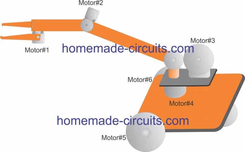
The following figure gives us the clear picture regarding the various motor positions and the associated gear mechanisms which needs to be installed for implementing the project:
In this design we make sure to keep things as simple as possible so that even a layman is able to understand regarding the involved motor/gear mechanisms. and nothing remains hidden behind complex mechanisms.
The working or the function of each motor can be understood with the help of the following points:
- Motor#1 controls the "finger pinch" or the gripping system of the robot. The movable element is directly hinged with the motor's shaft for the movements.
- Motor#2 controls the elbow mechanism of the system. It is configured with a simple edge to egde gear system for implementing the lifting movement.
- Motor#3 is responsible for lifting the entire robotic arm system vertically, therefore this motor needs to be more powerful than the above two. This motor is also integrated using gears mechanism for delivering the required actions.
- Motor#4 controls the whole crane mechanism over a full 360 degree horizontal plane, so that the arm is able to pick or lift any object within the full clockwise or anticlockwise radial range.
- Motor#5 and 6 act like wheels for the platform which carries the whole system. These motors can be controlled by moving the system from one place to another effortlessly, and it also facilitates east/west, north/south movement of the system simply by adjusting the speeds of the left/right motors. This is simply done by reducing or stopping one of the two motors, for example to initiate a right side turn, the right side motor may be halted or stopped until the turn is executed fully or to the desired angle. Similarly, for initiating a left turn do the same with the left motor.
The rear wheel does not have any motor associated with it, it is hinged to move freely on its central axis and follow the front wheel maneuvers.
The Wireless Receiver Circuit
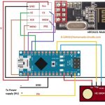
Since the whole system is designed to work with a remote control, a wireless receiver needs to be configured with the above explained motors. And this may be done using the following Arduino based circuit.
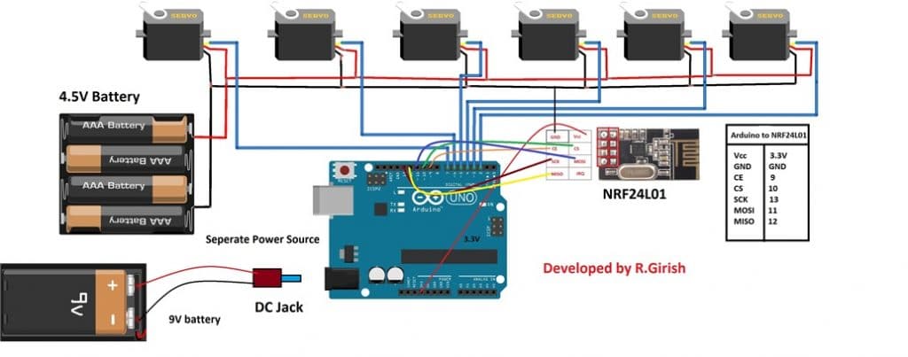
As you can see, there are 6 servo motors attached with the Arduino outputs and each of this is controlled through the remote controlled signals captured by the attached sensor NRF24L01.
The signals is processed by this sensor and fed to the Arduino which delivers the processing to the relevant motor for the intended speed control operations.
Thsignals are sent from a Transmitter circuit having potentiometers. The adjustemenst on these potentiometer control the speed levels on the corrsponding motors attached with the above explained receiver circuit.
Now let's see how the transmitter circuit looks like:
Transmitter Module
The transmitter design can be seen having 6 potentiometer attached with its Arduino board and also with another 2.4 GHz communication link device.
Each of the pots are programmed for controlling a corresponding motor associated with the receiver circuit. Therefore when the user rotates the shaft of a selected potentiometer of the transmitter, the corresponding motor of the robotic arm starts moving and implementing the actions depending upon its specific position on the system.
Controlling Motor overloading
You may wonder how do the motors limit their movement across their movable ranges, since the system does not have any limiting arrangement for preventing the motor from overloading once the respective mechanism movements reach their finish points?
Meaning, for example what happens if the motor is not stopped even after the "grip" has held the object tightly?
The easiest solution to this is to add individual current control modules with each of the motors so that in such situations the motor remains switched ON and locked without burning or overloading.
Due to an active current control the motors do not go through an overload, or over-current conditions, and they keep operating within a specified safe range.
Complete Program Code can be found in this article


Questions & Answers
hello sir
my name is Swati
sir I want build buck converter with input voltage 12 v pls provide the details of rating of the components ( with Arduino).
Hello Swati,
Please post this question under the following article, I will try to help:
https://www.homemade-circuits.com/buck-converter-using-arduino/
Sir thanks for communicating. Getting impetus from your project 10 Remote switch with nRF24l01 i tried to build 5 sets of Remote switching bidirectionally to operate from 15 meter distance with arduino Uno and Nano. It works, but stops frequently sending and receiving radio signals on testing place side by side/ Power supply and hardware checked and found no issue. I am not used to with code. hence i need any professional help to resolve the issue.
best
9748740387
You are welcome Subhasis, I understand your problem, however it will be difficult for me to troubleshoot the issue since I do not have any expertise in the field of Arduino. All the Arduino articles in this website were contributed by external authors.
No issue sir, if it not within the scope i can opt other way not arduino. But i need to send& received 5 inputs bidirectionally. I suppose it must have other alternatives. I can this as complete solutions without go into troubleshoot. If in anyway or by anyone. plz..
Subhasis, the nrf24L01 can be operated only through an Arduino microcontroller, it cannot be operated using other discrete methods, therefore the solution is still not within my reach.
By the way did you go through the datasheet of the IC? It might help you to troubleshoot the issue you are facing
https://www.sparkfun.com/datasheets/Components/nRF24L01_prelim_prod_spec_1_2.pdf
Good article.
If possible please share video .
Sure, If I make it I’ll post the video!
Please sir ,I want to build a variable DC voltage source or supply to be used for testing my circuit after designing it,but I don’t have or know the circuit.
Pls send it to me.
Akinbi, there are plenty of designs posted in this website, please use the search box to find them