The explained Ultrasonic Pest repeller is a device that generates ultrasound or a very high frequency noise in the range of over 20 kHz which becomes useful for repelling or scaring away animals like stray dogs, cats, mice bats, etc. This becomes possible since these animals are able to easily detect the frequencies at this range and find it disturbing in their ears, while humans remain unaffected due to lower hearing range.
What is Ultrasound or Ultrasonic Frequency
Animals like dogs, mice, bats have the ability to pick up sound frequencies up to 40 kHz. There are various types of bugs and pests which are also able to hear or respond o sound frequencies at this level.
Sound frequency at this level are classified as ultrasounds and could be used in a number of trial and error and functional applications. The unit explained here can be best applied to discourage stray dogs and other undesired animals, in scientific studies, and several other intriguing purposes.
The proposed circuit here generates a non stop sound frequency which may be quite above the capacity of human ear to perceive, that is over a range between 18,000 and 40 kHz.
How the Circuit Works
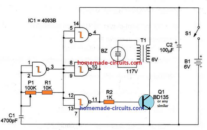
A single IC 4093 which has quad Schmidt NAND gates is used here for the generation of the required frequency.
Only one gate out of the 4 is used as an oscillator via the RC network, P1, R1 and C1. All these 3 components determine the frequency of the output and can be adjusted for optimizing the output response. The remaining 3 gates are rigged as buffers for providing sufficient driving current for the transistor.
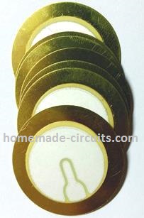
The indicated piezoelectric transducer includes its optimum output power between 700 and 3,000 Hz, although it may also work at greater frequencies but generating a lesser amount of power. The recommended power supply is a 9-volt battery.
This project generates ultrasonic frequencies approximately between 18,000 and 40,000 Hz, although it is possible to easily adjust this range by altering C1, within the values of 470 pF and 0.001 uF. Frequency could be fixed through P1 in the range as determined by C1.
Please note that the maximum range of frequency that can be generated by the IC 4093 is 500 kHz. The complete circuit diagram of the Ultrasonic Generator can e seen in the below shown figure
Parts List
- lC1 - 4093 IC
- Q1 - BD135 medium-power NPN silicon transistor
- BZ - Piezoelectric transducer
- T1 - Transformer: primary 110 VAC; secondary 6Vx100 mA
- R1 - 10K, 1/4W, 5% resistor
- R2 - 1K, 1/4W, 5% resistor
- P1 - 100K trimmer potentiometer
- C1 - 4.7nF ceramic or metal film capacitor
- C2 - 100 uF/16V
- S1 - SPST toggle or slide switch
- B1 - 6V or 9V - AA cells or battery - see text
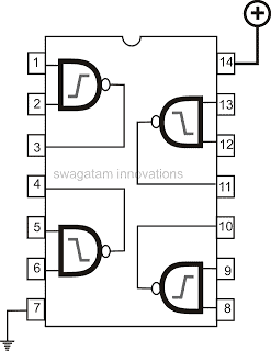
IC 4093 Pinout Image
Piezo Transducer Image
Components overlay and the PCB track layout can be seen in the following image.
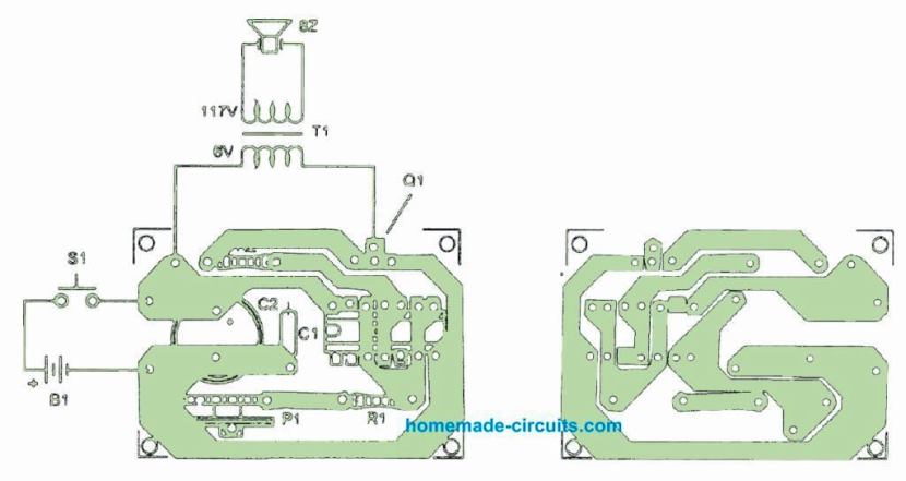
The entire circuit could be encased inside a compact plastic material container. The transducer or the piezo element may be installed on the front board.
Be careful with the placement of the parts that carry polarity, for example the transistor, electrolytic capacitor and power supply input. If the unit is intended to be operated continuously, make sure Q1 is mounted on a proper heatsink.
The transformer specs is not an important factor. Any transformer having a secondary coil ranging from 100 to 500 mA could be used in this ultrasonic pest repeller project.
Ideas you can Tweak Further
To find out more regarding the circuit or to improve its effectiveness:
- You could try replacing the piezoelectric transducer with a tweeter and check the response, whether it improves or not.
- Remove T1 and BZ and place the tweeter between positive line and the transistor collector. You might also try measuring the level of the generated ultrasound power?
- The circuit can also be tweaked to generate sound within the human listening range.
- This can be done simply by replacing C1 with any other capacitor having value in between 0.02 and 0.1 uF.
Insect Repeller using IC 555
Using an uninterrupted sound frequency to repel or attract insects may actually be possible in real life.
The range of frequency or depth may depend on the implementation and the type of pest, which can be perhaps determined through some trials.
The circuit displayed below produces a nonstop noise frequency you can use to push away (or draw in) several types of insects.
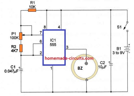
The circuit could be driven by 9V battery packs which may run for a long period of time due to its minimal current consumption. The center of the circuit is the 7555 lC, a CMOS timer configured as an sound oscillator which operates a piezoelectric transducer.
The parts positioning on a do-it-yourself PCB is revealed in the below given Figure.
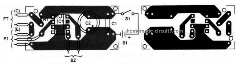
Precise location may not be too critical. Each of the parts and the power supply could be enclosed in a compact plastic-type container. Transducer BZ can be a crystal earpiece or a piezoelectric transducer.
Location of the polarized items, like c2 and the power supply, should be cautiously wired.
Applying the insect repellent can be quite simple. You have to fine-tune he trimmer potentiometer P1 to generate a noise having the identical throw, matching the insect's range you would like to repel.
Trial and error has to be done before you uncover the ideal frequency to repel a certain insect.
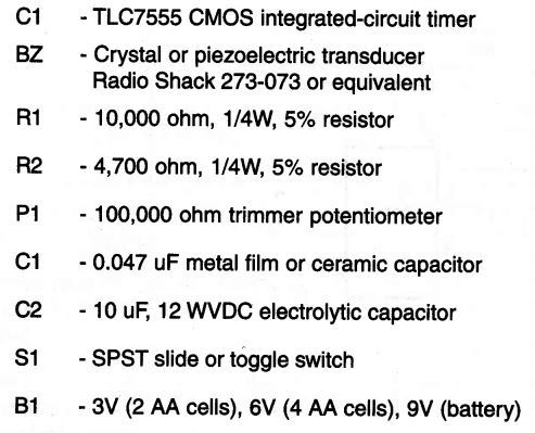
Parts List
Pest Repellent Circuits which were Tested and Found Working
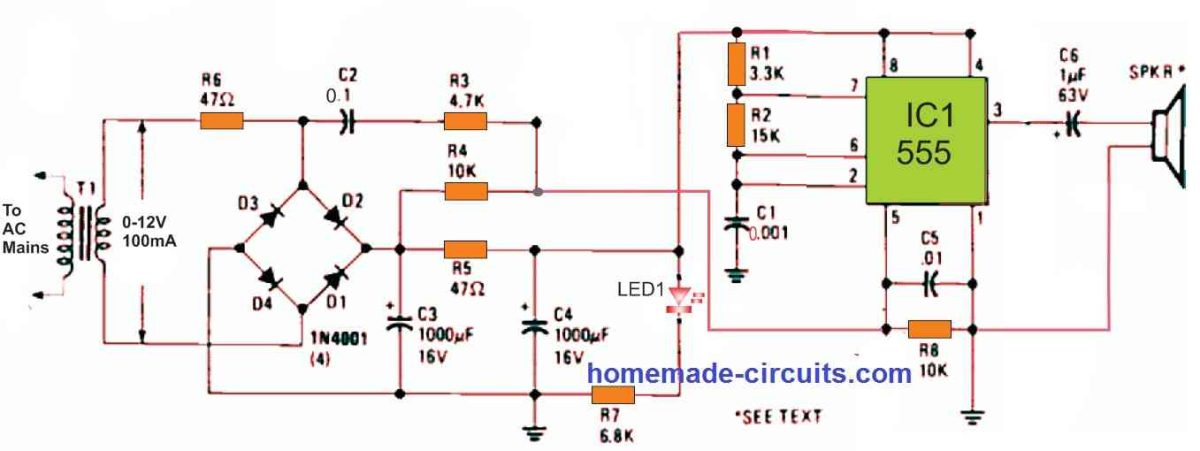
The circuit of the pest repeller we investigated is shown in Figure 1 above. We were startled to see that the circuit had only a single 555 timer IC wired in the manner of a squarewave generator. According to the parameters of R1, R2, and C1, its frequency was about 45 kHz.
A modified trapezoidal voltage waveform applied to pin 5 of the 555 timer modulates the 45-kHz carrier. A combination of C2, R3, and R4 linked across one endpoint of the bridge rectifier generates the modulating voltage. An oscilloscope examination revealed a sweep of roughly 20kHz on each side of the base frequency.
A 2 inch piezoelectric tweeter serves as the speaker.
The circuit shown in Figure 2 below is a pest repellent reported in one of the French electronics publications. The author says in the study that frequencies ranging from 20 to 40 kHz induce very painful cavities to develop in the brain fluids and blood arteries of mice and insects, leading them to flee. Radiated power could be as little as one-third of a watt.
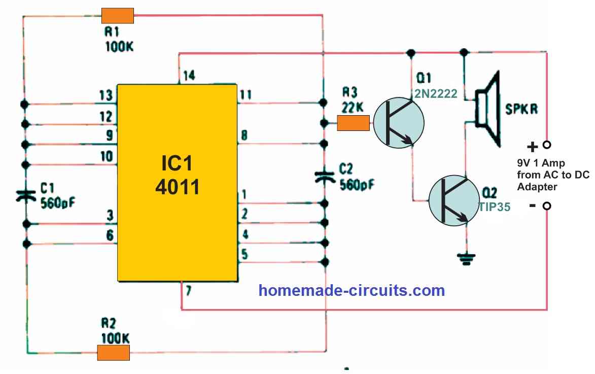
A quad two input NAND gate is wired as a multivibrator in the circuit, which operates at roughly 40 kHz. A residual 120 Hz sawtooth on the power supply line regulates the ultrasonic frequency with the least amount of filtering in the power supply.
A couple of Darlington-connected NPN transistors enable power amplification for driving the speaker optimally.
The circuit in Fig. 3 below is perfect for experimenting with the effects of continuous or pulsed high-frequency signals since it may provide either a continuous or pulsed output.
The idea was developed by Signetics.
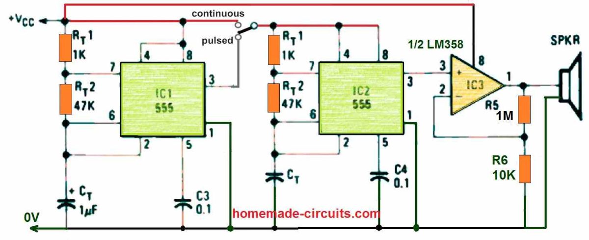
Referring to the circuit, one 555 timer, IC2, creates an ultrasonic squarewave at a desired frequency of 20 kHz. An additional 555, IC1, can provide that signal constantly or like an on and off switched signal.
It is simple to experiment with frequency and duty cycle. The duty cycle is the percentage of time spent "on" in comparison to the overall period, and it may be regulated from little more than 50% to nearly 100%. The duty cycle of the astable multvibrator circuit is determined by the timing resistors RT1 and RT2, and is equal to RT1 + (RT2 / RT1) + 2RT2.
The ON time could be expected to be 100% if RT1 is extremely small in value and while restricting the current via the discharge transistor to the maximum, as per the data sheet, the on time is near to 100 percent.
The 555's discharge transistor is an open-collector NPN device with the collector connected to pin 7 and the emitter connected to ground at pin 1. Because the maximum current through it varies depending on the manufacturer, you should double-check the manufacturer's data sheet to be safe.

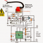

Questions & Answers
hello, interesting the project I ask if the transformer goes well 220v not available of the 110v. thanks
Thanks, 220V can be used, in that case use primary rated at 0-12V, and the battery 6V or 9V
I am looking to build an ultrasonic dog deterrent. Do you have any suggestions?
Thanks
You can try the last concept shown in the above article. You can replace the piezo with a tweeter device for maximum efficacy
Printed board is wrong.On 7555 is pin 3 output and on printed board is not.Short conected is beetwin the pins 3 and 6 instead pin 2 and pin6,piezo transducer have output on pin5.It is wrong!
The piezo elements are rated for +- 30V. But here 110V is used to drive it. Please clarify.
The datasheet may be mentioning 30 V but in most buzzer circuits the coil generates many hundreds of volts across the piezo which causes it produce a sharp ear piercing sound.
Dear swatagam
First circuit doesnt work i review connections and i didnt see a problem.Components are right
And transformer i use 220v/12v
What should i have? Thank you for answering
Trishopta, the first circuit is very straightforward oscillator circuit and will surely work. Pleas use a frequency meter to check the frequency at the pin3 of the extreme left gate, and at the transistor base, collector etc….this will prove whether your circuit is oscillating or not.
I checked its oscillating.I think there is a problem with transformer what can i use instead of it?(Audio transformer 1k/8ohm , coil?how much uH?) Good day
Yes, all types of types transformer should work, since a transistor stage is used as an amplifier.
Thank you for giving information.I have questions on pest repeller project.can this project use to attract or repel grasshopper .know a day grasshopper is big problem in my country if you have an idea or knowledge please share it.thank you
It can repel grasshopper if the power and frequency of the piezo are correctly adjusted, this will need to be done with some trial and error
Hello there, I’m ordering the parts for the first circuit (Ultrasonic Pest Repellent Circuit). I can find all the parts except for R1 and R2 … does anyone know where you can find a 100 watt, 1k and 10k resister? Is there a substitute, like a 1 watt? Does the wattage really matter?
Thanks! -djt
Hello, A 100 watt resistor wouldn’t be required for this small project, it was obviously a printing mistake. You can check out the parts list now, they are actually 1/4 watt rated.
what is the range of this circuit to repelling or scaring away animals? like 100m 200m……
may be 10 meters….
Ultrasonic Pest Repellent Circuit, cosa è una presa per il culo?
Two questions if I may,
1). Has anyone had success with this design?
2). Is there a place to order these (and other) project boards without going through the hassle of editing a new board when others have done that work already?
Hai
What about using Ultrasonic transducer used in Ultrasonic distance measuring ?
It can be also used!
What about using pure sinewave oscillator instead of rectangular waves?
Will it be efficient to use ferrite core transformer at this frequency
can make custome made ferrite transformer?
Please give core/bobbin size , primary and secondary turns ratio.
Or
Can we use flourescent emergency light circuit board after its frequency ?
For sine wave output you will need a sine wave oscillator circuit.
I don’t think the transformer is required, instead you can use a simple buzzer coil at the collector of the transistor, and connect the piezo parallel to the coil:
https://www.homemade-circuits.com/simplest-piezo-driver-circuit-explained/
I’m a student and i’m trying to make a frequency which deters mosquitos, I need to achieve a frequency which is >38kHz but <44kHz. Should i just replace the piezo transducer with a tweeter?
Tweeter can be used, however a piezo looks more suitable.
I tried using a piezo transducer however the frequency wasn’t high enough.
the piezo must be enclosed inside a suitable enclosure as shown below. And above 15 kHz the audio will be impossible to hear.
I need the frequency to be even higher…(out of the hearing range of humans)…How can i do this with the implementation of a speaker instead of a piezo?
You won’t get good results with a speaker for frequencies above 20 kHz. You will have to use a piezo transducer
What is the max frequency that can be emitted by a piezo transducer?
It can be in MHz
So, if I wanted smthing in kHz, what output device should I replace?
If it’s below 15 kHz, you can use a speaker or tweeter, otherwise you can use a piezo.
I used a speaker but it just made it louder…I’m yet to try a tweeter.
Anything above 15 kHz should be inaudible to human ears.
With my respect to Mr.Swagatam all pests are wery soon&fast adopted to these ultrasonic noice
(permanent beeeeeeeeee at fig.1 or permanent be–be–be–be–be– at fig.3) – in a few hours or faster. Only self-ascnoleged risc – to don’t hear a raptor through the ultrasonic noice – is force these mice-rat-pests to go fare of the noice. For mosquito-buttrefly-fly pests real defence radius is 1-1.5 meters or less – depends on wind and on relative humidity of air. For all bugs-werm-termitos-pests all sounds are inert. It mean – the kind of devices is almost useless.
The ultrasonic noice make cats and dogs too nervouse=agressive. For humans the ultrasonic repellents is made both: waste of money for device with in did not-defenced property.
Apologues for my English and for broken hopes.
Igor, the last three circuits have been tested by engineers and found to be working, so although in some case it may not work but it is not useless, it definitely works in many of the cases.
Thank you Igor, for your valuable feedback!
I have to produce from 18k- 45khz continuosly varying frequency ,which vary from 18k-45khz within 10 min automatically and should continue until we stop the power….
How can I do this
You can probably try the concept explained in the following article:
https://www.homemade-circuits.com/home-emf-radiation-protector/
You can change the INDUCTOR with a piezo transducer
Can we Replace those NE555 wit a Single NE556?
Yes that’s possible.
Do you have a youtube video to show this will actually stop dogs barking ?
Very great and useful
Large flocks of birds descend on my fruit trees each summer. They are now too large for me to net, although pruned every year. I would like to have an ultra sonic bird scarer to place underneath the trees with the sound spreading up through the branches. …. in a shape spreading outwards from the base unit to cover the shape of the tree. A motion sensor is of no use due to the windy environment. The trees are placed in three different locations around my backyard. The scare units would need to be battery/solar operated. They would only be in use during summer fruit season. The commercially available ones do not suit my backyard situation. A successful invention would be a winner here in Adelaide as our environment is mostly fruit fly free and everyone I know with fruit trees has the yearly struggle to cover and net their trees. I grew up in and orchard area where gas guns were the norm – Not advisable in the suburbs! Any inventors up for the challenge? Thank you.
I understand your problem, but the question is, can ultrasound frequency make any impact on birds? If yes then I think the following circuit can be effective. However, to make the sound louder the speaker would need to be driven through a power transistor coupled to the output of IC3
Hello, sir! In your opinion will the circuit work from 12V DC in figure #2?
Hi Sergei, yes figure#2 will work with 12 DC, use a piezo tweeter for the speaker.
Good day. Mr Swagatam can I use this 4093 circuit ultrasonic generator with 40kHz piezo transducer to clean various items. I have a stainless steel tub with a piezo transducer glued on. A power of 50W would be enough for me.
Hi jiri, the 4093 circuit will not be able to generate 50 watt power, however if you remove the transformer and use a TIP122 transistor directly with the ic output through a 10k base resistor then its collector can be used to drive a 50 watt transducer
Mr. Swagatam modified connection as you wrote me does not work for me. When connecting the circuit, I calculated the following values: Un is 12V, frequency 40kHz, duty 90%, Ub is 1.15V and Uc is 0.47V. The piezo transducer has a capacitance of about 7nF. After connecting the piezo transducer, the frequency behind the resistor drops to almost 0. Could the piezo transducer be defective? Thank you.
Hi Jiri,
Did you use the transistor TIP122 as suggested previously?
Yes, I used a TIP 122 transistor.
If you connect the transducer at the collector of the TIP122, the frequency output of the IC cannot become 0. If the Transducer is short circuit then the transistor will heat up.
hi sir
I’m given an assignment to build an ultrasonic pest reppeller. please which working circuit should I try?
Hi Audu,

I think you should try the following design:
Keep the switch in the pulsed mode.
I have built the circuit sir but the buzzer is making a pulse noisy sound .
What value have you used for the capacitor CT? Please try 0.001uF for Ct and check again.
pls Can you give me program in C or basic language to generate alarm signal and description of the wave form of this signal, because i want to build a siren with a microcontroller.
Sorry, my microcontroller knowledge is not good, so it won’t be possible for me…
Thank you very much for your quick response I will build it. On the other hand I want to ask you 2 questions, first tell you that I never had oscilloscope and I want to buy one, now the first question is…. Is it really necessary to have an oscilloscope for electronics repair? And the second one is that you have a lot of experience, could you do a good tutorial on how to use an oscilloscope, how to make averages, etc etc etc.
You are welcome Carlos,
Regarding your 1st question, an oscilloscope may be actually necessary only when critical waveform analysis is required in a circuit, otherwise a simple DMM is enough to verify the circuit working.
I have used the following oscilloscope with outstanding results, which is very effective and cheap for basic waveform analysis of any circuit. I think you should really try this device and have fun understanding the waveform patterns of relevant circuits:
https://www.homemade-circuits.com/dso138-best-small-oscilloscope-for-electronic-hobbyists/
Hello Mr. Swagatam good morning, in this opportunity I want to ask you if you have a somewhat powerful circuit not (too much) since the area to be covered is not so large. Ultrasonic as I am having problems with rodents (rats) and I want to eliminate but it would have to be a circuit that is changing frequency so that they do not get used to the same frequency and return …. Thank you very much Mr. Swagatam.
Hello Mr. Carlos,
yes the last design by Signetics can be modified for an increased power output, by eliminating the op-amp completely and the connecting the speaker with pin#3 of the IC2 through a 10uF capacitor.
Since the sound output is intermittent, changing the frequency might not be required here.
Hello good afternoon Mr. Swagatam, with respect to the rat repellent circuit, I want to tell you that the circuit of figure 1 with 555 which takes part of the signal alters to pin 5. That circuit has mounted a friend of mine from Argentina and it really works very well, the problem here in Italy is that I can not find a transformer. Only switching power supplies… The question is that how can I replace the transformer but being able to take that alternating signal? Thank you very much
Thank you Carlos, for this valuable information and update.

However, in the referred circuit design, a transformer is a must for getting the perfect half sine waves at pin#5 of the 555 IC and the intended modulations. Unfortunately, without transformer this might not be possible at all:
Hello, good afternoon, Mr. Swagatam. I would like to ask you a favor. How can I increase the power of this rat repellent circuit with Lm555? I am attaching the circuit diagram. Thank you very much.
Hello Carlos,

You can try modifying the circuit in the following way, to convert it into a high power version. Let me know how it goes…
The circuit is really good and I know it really works, but this time I have to cover a longer distance…
Hi, i am Ghandy, a hobbyist. i built an ultrasonic pest and rodent repellent circuit of figure #3 and use electrolytic cap 1uf to gnd and a buzzer at output but there is continous audible sound
Hey Ghandy, did you put the switch to “pulsed” position? And please remove the LM358 IC, it is not required, and connect the speaker directly with pin#3 of IC2 through a series 22uF or 10uF capacitor….
Also try increasing the Ct 1uF value to 4.7uF and check the response…
Mr. Swagatam, I’ve been seeing your circuit analysis and comment responses for years. I must tell you that I think you’re a gentleman and a scholar, in the way you address peoples’ comments, questions and requests. I appreciate all of your impeccable knowledge of discreet electronic components and I hope I continue to see your circuit diagrams and the invaluable information that you provide with them. I’m a huge fan!! May God Bless You and keep You healthy!! Thank You, my good man..
Thank you so much Chris for your kind words and support! It means a lot to me. I’m glad my circuits and explanations are helping you. God bless you too!
Good morning Sir,
I really want to once more appreciate you for your great contributions to my projects.
Especially as the circuits you post have been very effective.
Sir, right now our community hear is challenged by elephant conflicts. Farms are been destroyed by elephants.
So I am embarking on a project to see if something can be done. Either electric fence or Ultra sound repellant.
Can figure 3 be used?
IC3 seems to be for amplification, what transistor circuit can cause the output to be more powerful.
Good evening Godwill.
Elephants being very large animals, ultrasonic repellers might not work, so a fence charger looks like a better choice to deter these huge animals.
Good evening Sir.
Thanks very much.
Sir, can you help with the design of a solar powered electric fence diagram?
It should use a PIR(motion sensor)
Godwill, please give me your solar panel specifications, I will try to figure it out…
Good afternoon Sir and happy Sunday.
1) 400Watts Solar Panel.
2) 100Ah Lithium battery
Good Morning Godwill,
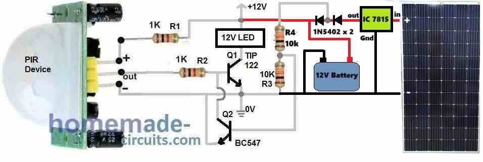
I think the following circuit will do the job for you. You just have to replace the “12V LED” load shown in the diagram, with a 12V inverter….and then feed the inverter 220V output to the fence charger.