This article discusses a simple ultrasonic sound sensor alarm circuit which may be appropriately set for detecting sound pressures well above the normal human listening capacity, that may range from 20 kHz and over.
Ultrasonic Concept
Ultrasound or ultrasonic sound waves was probably invented even before humans existed on this planet by a few of the animal species such as the bats, dolphins, and similar other creatures. These are basically used for locating distant objects which might be a potential prey for these animals.
The signals are emitted by vibrating special organs present in these animals which are reflected back from a potential prey in front and thus the creature is able to locate the prey by judging its exact location through the reflected waves and is able to hunt them down.
Humans could discover ultrasound quite late, but nevertheless here we will study how a simple ultrasound detector can be made and used for detecting these high frequency signals inaudible to a normal human ear.
Circuit Diagram
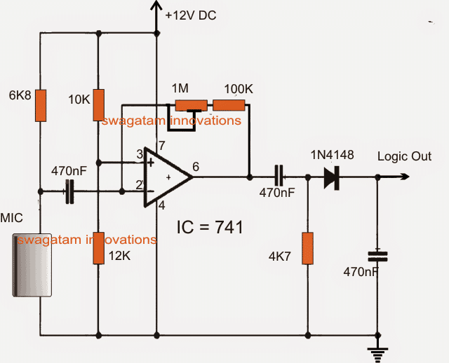
The figure above shows a simple IC 741 based ultrasonic sound sensor alarm circuit.
The detecting device used here is an ordinary electret condenser mic. The mic input is fed to the inverting input of the IC pin#2.
How it Works
Pin#3 of the IC is appropriately clamped to a suitably selected reference voltage with respect to the pin#2 of the IC.
A feed back link can also be seen via the 1M preset across the output and the inverting input of the IC. This feedback link makes the IC work like a highly sensitive inverting amplifier.
The MIC is thus set to detect ultrasonic pulses that might be naturally emitted from any relevant source such as when an electronic instrument like a TV, DVD player etc is switched ON, or a mobile call in the vicinity is sensed. A car ignition could also make the circuit trigger with an alarm.
The detection gain or sensitivity range of the circuit can be set by adjusting the shown 1M preset.
When a high frequency sound in the ultrasound range is sensed by the mic, results in a high logic pulse to generate at pin#6 of the IC which is appropriately dimensioned, and rectified by the output configuration consisting of the series 470nF coupling capacitor and the associated diode, resistor, capacitor filter design.
The high logic may be used as an input to a MCU circuit or simply for driving a relay driver stage.


Questions & Answers
How would the output be displayed?
Dear Swagatham
Can I use this as a BAT DETECTOR circuit…..? They emits Ultrasonic sound.
I don’t have 741 ic, but have LM4558, LM358, TL082 etc…. Can I use these ic’s (half part)….?
Dear Anil, this circuit was referred from another website, so I am not sure whether it will really do the job as they specified or not, you may have to confirm it with some trial and error
good day sir
i have an ultrasonic module ( which can be used for adruino ) how can i use this module in normal circuit to make a proximity detector. is that possible ?
if so can u pls suggest me a circuit so that to use this sensor module as proximity sensor
thanks
john
John, I do not have sufficient information about it at the moment so can't suggest much about this concept, but I'll try to investigate and post the details as a new article if it's feasible.
can I put an LED at the output?? what resistor should I use? tnx ^_^
yes you can, preferably through a transistor driver stage
How?
base to "logic out"
emitter to ground.
and LED between collector and positive through a 1K resistor