This simple homemade mosquito swatter bat neither requires a circuit nor a battery for the operation. The entire design works using a single high voltage capacitor and through quick charging from mains AC socket. (Designed by me)
Introduction
In a few of my earlier posts I have discussed how to make mosquito zappers using the conventional high voltage circuits, and using chargeable battery for generating the high voltages.
Such swatter bats work great but they have some serious drawbacks.
These units use a fairly complex circuit which require a calculated inductor and a switching circuit. The second complex thing in the design is the bat mesh which cannot be hand made and require special equipment and tools for the assembly.
Moreover the battery used with these bats being cheap are prone to faults and finally become useless, or require frequent repairing, which usually become difficult for a layman user.
All these complexities finally compel the user to dump the bat in a scrapyard and go for a new one.
The design explained in this post is quite unique, and is free from all the above downsides, and complexities.
The main features of this battery-less mosquito bat can be understood from the following points:
1) The bat mesh uses a PCB and solderable wire assembly which makes it easier to construct by any user having ordinary technical skills.
2) The bat uses a single high voltage capacitor for charging the mesh, and gets rid of the complex switching circuitry.
3) The high capacitor can be charged directly from the AC mains, and therefore the design does not have to depend on costly NiCd or Li-ion battery, and long charging periods.
You might have by now understood the unique features of this bat, let's move ahead and see how simply this mosquiito bat without battery may be constructed by anybody at home.
How the Bat Mesh is Designed
Referring to the figure below, which looks quite self-explanatory, we can understand the details from the following points:
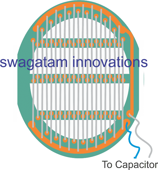
- The green base background is actually a PCB, with copper tracks etched on it, shown in orange.
- The PCB is elliptical in shape with a large central cut out, and a couple of horizontal ribs to enforce better rigidity to the PCB frame.
- The grey lines are tinned copper wires, around 0.5mm in thickness, tightly stretched and soldered end to end across the indicated copper tracks. The wires are alternately arranged and connected with the respective power line tracks, on either side of the layout.
- The wires are also soldered in between across the two central ribs to reinforce them with increased rigidity and firmness.
Designing Swatter Bat without a Battery
That's it, the bat mesh is now ready.
Now I have explained how the stem or the handle of the bat is designed, and the electrical specification details in the following section:
The next image below details the integration of the bat mesh with the handle and the electrical wiring which needs to be done within the internal space of the handle:
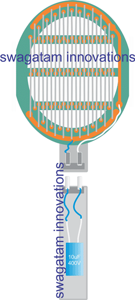

From the images above we can identify the following connection and wiring details:
- The handle upper and lower assemblies preferably needs to be a push-fit type, with corresponding male/female AC pins, such that when the two sections are push-locked, the pins also get plugged in with each other.
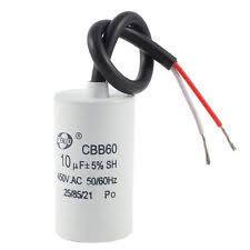
- The lower section of the handle can be seen enclosed with a 10uF/400V capacitor (Non-polar), whose terminals are electrically wired with the external plug pins.
- This section of the handle plays a twin role, first it allows detachment from the bat and plugging into your home mains socket for a 1 second quick charging, and next, the same plug pins are allowed to be inserted back into the upper bat section for arming the bat mesh net.
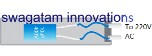
The following figure shows how the lower handle section needs to be detached and plugged to an AC socket for charging the internal 10uF capacitor, (for a 1 second charging).
How the Swatter Bat Works without a Circuit or a Battery
Through the above discussion, you might have already understood the concept, where a high value charged capacitor is used for electrifying the bat mesh and electrocuting the bugs or mosquitoes flying between the parallel wires of the bat net.
That looks pretty simple and doesn't need much of an explanation.
Some Technical Necessities
The proposed design uses a single capacitor for the charging the mesh, which implies that the voltage level is significantly reduced across the net wires, as compared to the conventional bat designs.
Therefore in order to make the design effective, it is important to keep the wires soldered on the bat PCB to be not more than 0.8mm away from each other.
Anything above this distance might allow our tiny friends to dodge away the fence, and to safety.
Warning:
Anything that comes easy invariably possesses some hidden drawbacks and dangers. Here too, although the bat design looks straightforward, the mesh network is held completely exposed to an accidental human touch.
Therefore, once the charged capacitor is hooked-up with the bat mesh, be very cautioned not to allow any of your body part to come in contact with the bat mesh.
Otherwise that could cause a painful memorable jolt to your body. Since the shock is from a capacitor, it won't be lethal, nevertheless it could be quite nasty.
Questions & Answers
Where do i get PCB, wire and Handles
It is not available from this site. You can search it in amazon, or ebay….
I bought a swatter and it stopped working in just 2 weeks. I want repair it is there any way or procedure?
If the red LED is not lighting up and the net is not damaged or touching each other then most probably the battery is down. If charging does not help then replace the battery with a new one and check the response
Simple But, Dangerous ! Will it Charge faster or and/or Discharge slowly if we connect a Diode in series to the Capacitor ?
A diode cannot be used because then the plugin system will not work the bat mesh.
Tell me please,sir! If a cat stands on the ground and touches the Swatter Bat, will it die?
It will not die but can get a very nasty shock.
Thanks a lot! And I’m very worried about my cat. He is very curious.
Can you tell me how to make a light indication of the discharge of a capacitor? How to understand that the capacitor is discharged?
Is it possible to make it so that you connect the device to the electrical network, see that the capacitor is charged, then start using the device, and when the indicator shows that the capacitor is discharged, put the device back on charge. I understand that the charging process takes a few seconds, but it would be nice to provide such a device with a discharge and charge indication.
Unfortunately it is not possible to provide a light indication because connecting a lamp will discharge the capacitor and then the bat cannot be used for the intended purpose. If some other method is used that will require an extra battery for the indicator.
Hi Sir Swagatam
Hello. Thank you very much for your response. I will always remember your kindness.
Bye
It’s my pleasure Philips!
Hi Sir Swagatm
By everyone, I meant that if I use such capacitor in your said project.
Please accept my excuse
Bye
No problem philip!
Hi Sir Swagatam
Hello again. Thank you so much for your feedback I got the concept. would you please answer my last question and tell me what will happen if somebody uses the capacitors in which the multi meter needle does not return to zero. it is very important to me.
I appreciate you for so patiently answering persons like me who are very weak in electronics but are very eager to know.
Wish you all the best
You are welcome Philip, if the meter needle is not returning to zero shows a faulty capacitor, it means there’s a continuity inside the capacitor
Hi Sir Swagatam
Good day
1st. I thank you a lot for your detailed reply for which I am very glad, kind and honorable man.
2nd. I am about to do your interesting project and I do not understand what did you mean of APPLICATION. would you please explain a bit?
3rd. Since I do not have a capacitor meter, I set my Regal analogue multi meter on *100 ohm scale to see that the capacitor is good or not. When I connect one 20 Mf capacitor to it, the stand of multi meter moves to the middle of the screen and gently returns to zero while for the second capacitor it does not returns to zero. I want to know if it is safe to use this one when neede. would you please tell me?
I appreciate your feedback dear sir.
Bye
Thank you Philip, the “application” was referred to some other use of the capacitor, it was not referred to the above article concept, and therefore now I have removed that sentence from my comment since it was not relevant to your question.
The meter needle slowly returning to zero indicates a good capacitor. The capacitor first charges which causes the meter needle to rise, and when the capacitor is fully charged it stops any further flow of current through it, which causes the meter needle to return back to zero.
Hi Sir Swagatam
Good day. I have got a 10 Mf 400V polarized capacitor and I know that it is possible to charge it through 220V via bridge rectifier. I have also heard that it is a good idea to use a 1 k resistor between positive output of the bridge and the capacitor. Is that right and what is the role of this resistor ?
Thank you sir and bye
Hi Philip, the maximum peak voltage for the 220 V after bridge rectification will 310 V which is quite lower than 400V, therefore the 1K may not be required. The 400V determines the maximum tolerable limit of the capacitor, beyond which the capacitor can explode. If you connect 1K in series that will reduce the current to the capacitor, and the capacitor will not be able to charge with full current.
Dear Mr. Swagatam
Hello dear
Thank you very much for such a practical, simple, and very interesting project. All circuits I have seen so far in your site have been very ideal.
From time to time, lizards enter our house from the yard and insecticide sprays and commercial bat swatters are not able to kill them, as you dear know. would you please tell me How much should I increase the capacitance of the 10 microfarad non polar capacitor so that I can destroy them with this circuit? I have a Fuji digital flash camera circuit which has a 200 microfarad polar capacitor, and I can not use the whole circuit as a substitution for your nice project since I do not know the working voltage of it.
Do not hesitate to answer my question Please, since I am always very cautious working with mains supply.
He who loves you so much
Mike
Thank you dear Mike,
I am glad you liked my projects, however it will be difficult for me to help you with your mentioned requirement, because I believe that lizards are harmless, shy animals, and I cannot recommend to kill them in such a cruel manner. In my house these creature roam freely in and out of the house, and we have no problems with them. I hope you will understand my problem and bear with me.
Dear Mr Swagtam
Hello. Thank you very much for answering me. I am glad that you are so kind to animals. I am not a cruel man, either and feed birds and ants every day. We have seen that there are men who kill ants that flow their house.Instead, I find their nest and put them candy and … until they are full enough and their stores is full for the cold winter; thus they leave our house. Lizards are dangerous, as you may know because they have Cyanide in their skins and I have heard that all individuals of a family have been dead because of falling one into their food pot in a village of our country.
Thank you anyway for your answer and wish you all the best dear kind Swagatam.
Best regards
Mike
You are welcome Dear Mike, you may be true, but it’ highly unlikely that they will contaminate our food unless we keep our food unattended or open for longs periods of time. Moreover these animals are very shy and run away from heat and humans.
Dear Swagatam
I understand you and adore your feeling about these creatures. Now, after about two decades I clearly remember that the experts had come to the conclusion that the Lizard had certainly fallen into the food pot from the top of the tree in that village house.
I sincerely thank you for so caring your site visitors.
wish you smiling lips and healthy; kind man.
Best regards
Thank you dear Mike, I appreciate your explanation and feedback!
bro, I want to use my mosquito bat with direct home current wire connection.
we have 100-240v input at home, may i know how to make it.
Hello Satyam, you can use a 3V AC to DC adapter and connect its output to the points where your bat’s battery had been connected, and then use it for the intended purpose
How often to be charged.Once for each mosquito?
Can we recharge the capacitor after using a long time in a mosquito swatter bat. If Yes, Can you please confirm how much time it will take to recharge and how many hours it will be fully charged at one time charging.
Capacitor will need to be recharged each time a mosquito is killed…but charging takes just one second from mains socket. charge will remain for no more than 10 minutes
Oh thank you for replying but I want to keep atleast 3hrs constant charging for a one time charged. So, I can kill 100’s of mosquitoes. I should built strong battery less bat comparing to present bats and please suggest, how to built it.
sorry that is not possible without battery.
Hi Sir,
Please confirm the total cost of mosquito swatter bat which you have explained in a crystal clear way.
Kethesh, the PCB is the only costly thing and I have no idea about its price…
Hi Swag can you help in this?
I am making a DIY car for which I have to use 3.7V 3800mAh Li-ion Battery to connect with DC Electric Motor 3-6V.
Can you tell me if I can use battery of mosquito bat instead of 2X3.7V 3800mAh battery to connect with DC Electric Motors 3-6V.
Thanks
Hi Shaikh,
Mosquito bat batteries are never rated at 3800mAh, so you cannot use them. I would recommend a couple of 18650 batteries instead:
https://www.homemade-circuits.com/18650-2600mah-battery-datasheet-and-working/
please I want you to help design a universal bottle cap fragrance sprayer that can work with the size of a bottle mouth that can spray at interval. How to design auto spray for fragrance.
sorry I cannot help with the mechanical details of the sprayer, that you will have to purchase readymade
hello sir,
how long does the fully charged capacitor operate with the bat before recharging? mins, hours or days?
Hello Lawal, it will depend how many mosquitoes you have killed? otherwise it can last for many days, not sure about the exact period….
Well done, from what I see are there more simpler way to explain your diagram that is more explain. As a hobbits. to some one who does not know much about electronic. where can you advice I start
you are welcome! You can start by learning how the basic components like transistors, resistors and capacitors work in electronic circuits…
what i mean, i know little about electonics and it amaze me how you put things together. how best can I benefit from your works. to understand and grow like you what basic do i need to know?
you will have to go a long way by learning the basic circuits first step by step, you can start with the transistor circuits and try to grasp how the various configurations are set up to function.
please teach me in a layman language. how to get ride of walgecko
they are good, don’t drive them away
It’s been a while I’ve not been here this is why my message arrives quite late. I like to navigate on your site where I find usefull tips and ideas as well. Regarding the mosquitos bat, if the capacitor is fully charged, it can deliver (theorically) almost 400W, which is enough to stop some human hearts I think. Also, you must trust your capacitor manufacturer to connect it directly to mains, I know there shouldn’t be any problem, but imagine someone doing this with a capacitor coming from a cheap chinese device. You already write it but the cap must be non polarized and 400V at least.
I am glad you are back and liking my site!
As for the above concept, if the user finds the capacitor value to be on a little dangerous side, the person can always adjust it by adding a small value resistor in series with the net mesh copper layout circuit,
The resistor can be selected such that the output is sufficient to kill a mosquito but not so dangerous even to the folks with weakest of hearts.
If the capacitor is low quality it will explode, this explosion will not be at a level that can harm anybody, that said it is the user’s responsibility to make sure he gets the parts from reliable sources.