An oscilloscope is a device that measures and analyses signals in circuits. It's an indispensable equipment for everyone who works with electronic circuits since it enables them to see the activity of a wave in real - time basis. The DSO138 is one of the most popular oscilloscopes on the market today. We'll give a general description of the DSO138 and describe how to utilise it in this post.
What is the DSO138?
The DSO138 is a portable oscilloscope which is cheap and well-liked among electronics amateurs. Since it is a digital oscilloscope, the output is shown on the screen using digital signal processing techniques. The DSO138 is very simple to use, with an easy interface. The easy interface makes it ideal for novices.
The 2.4-inch TFT colour display on the DSO138 features a 320 x 240 pixel resolution. It can show signals with a highest sampling rate of 1Msps and a bandwidth of up to 200kHz. With a 1M input impedance, the DSO138 is adequate for the majority of applications. A 9V battery or a DC power source can power it.
How to Use the DSO138
Using the DSO138 is relatively straightforward. Here are the steps to follow:
Step 1: Connect the Probe
Connect the probe to the input connector on the DSO138. The probe has a ground clip and a probe tip. The ground clip should be connected to the ground of the circuit you want to measure, and the probe tip should be connected to the signal you want to measure.
Step 2: Power On the DSO138
Power on the DSO138 by connecting it to a 9V battery or a DC power supply.
Step 3: Adjust the Horizontal and Vertical Controls
Adjust the horizontal and vertical controls to set the time and voltage scales. The horizontal control adjusts the time scale, and the vertical control adjusts the voltage scale.
Step 4: Trigger the Signal
Press the trigger button to start capturing the signal. You can set the trigger level and slope using the trigger controls.
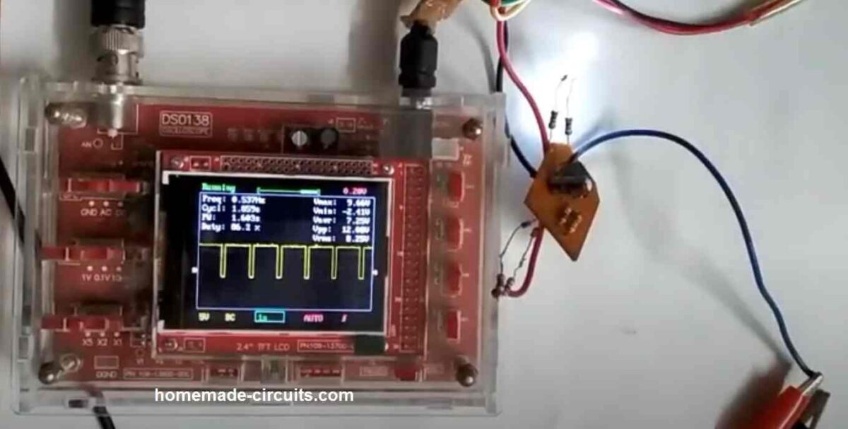
Step 5: Analyze the Signal
Examine the on-screen signal. The cursors may be used to calculate the voltage and time at various signal locations. The auto-measurement feature may be used to determine the signal's frequency, period, peak-to-peak voltage, and other characteristics.
Control Buttons of DSO138 Oscilloscope
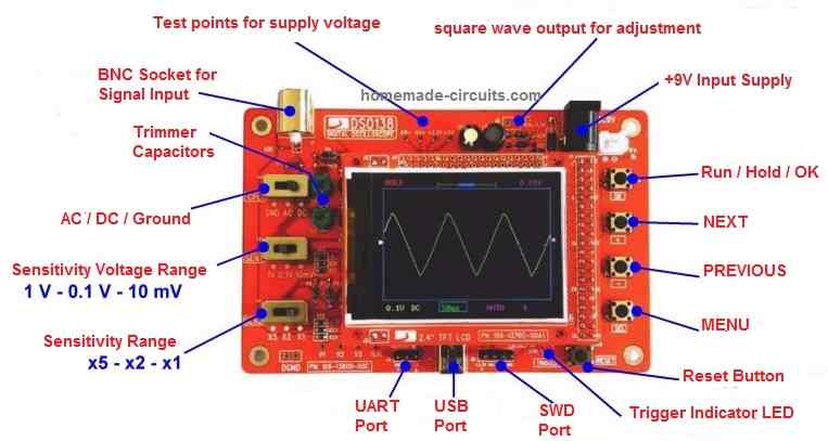
The DSO138 oscilloscope has several button controls that are used to adjust and configure various settings on the device. Here's a brief explanation of each button control:
- Power Button
The power button is used to turn the oscilloscope on and off. When the oscilloscope is turned on, the power LED on the board will light up.
- Auto Button
The Auto button is used to activate the auto-setup function, which automatically configures the vertical and horizontal scales to display the signal on the screen. This is useful when you want to quickly set up the oscilloscope to view a signal without manually adjusting the scales.
- Cursor Button
The Cursor button is used to activate the cursor function, which allows you to measure the time and voltage of different points on the signal. The cursor function is activated by pressing the button, and the two cursors on the screen can be moved using the horizontal and vertical controls.
- Trigger Button
The Trigger button is used to activate the trigger function, which is used to stabilize the waveform on the screen. The trigger function is activated by pressing the button, and the trigger level and slope can be adjusted using the trigger controls.
- Time/Div Button
The Time/Div button is used to adjust the horizontal scale of the signal. Pressing the button allows you to cycle through different time/div settings, which change the amount of time displayed on the screen per division.
- Volts/Div Button
The Volts/Div button is used to adjust the vertical scale of the signal. Pressing the button allows you to cycle through different volts/div settings, which change the amount of voltage displayed on the screen per division.
- Menu Button
The Menu button is used to access the menu system, which allows you to adjust various settings on the oscilloscope. Pressing the button once displays the main menu, and pressing it again cycles through the different menu options.
- Reset Button
The Reset button is used to reset the oscilloscope to its default settings. This can be useful if you've made a lot of changes to the settings and want to start fresh.
The DSO138 oscilloscope button controls are easy to use and provide a range of different functions that allow you to adjust and configure the device to your needs. By understanding how each button control works, you can quickly and easily adjust the settings to view and analyze the signal on the screen.
Advantages of the DSO138 Oscilloscope
The DSO138 oscilloscope has several advantages that make it a popular choice among hobbyists and electronics enthusiasts. Here are some of the main advantages of the DSO138:
- Low Cost
The most clear advantages of the DSO138 oscilloscope is its inexpensive price. It is a low-cost choice for people who are interested to buy an oscilloscope but do not want to spend a lot of money. This feature makes the DSO138 a great option for novices and amateurs just starting out in electronics.
- Portable and Compact
The oscilloscope DSO138 is small and portable. It may be utilised on a workbench, in a classroom, or outdoors and is compact enough to be transported around in a toolkit or handbag. It is a fantastic option for individuals who want an oscilloscope which could be readily transferred due to its portability.
- Easy to Use
The DSO138 has an easy to use interface which becomes extremely suitable for novices. It is not necessary to be an expert in the field of electronics to use this gadget because of its simple controls. Therefore, it becomes a great option for users who are new to electronics or who want an oscilloscope they can use immediately without much effort.
- High-Quality Display
The DSO138 features a high-quality display which allows the user to visualize and analyze signals easily. Its 2.4-inch TFT color display comes with a resolution of 320 x 240 pixels. This much resolution is more than sufficient for most applications. The display looks bright and clear, which makes it easy to read even in low-light conditions.
- Versatile
The DSO138 is a multipurpose oscilloscope which can be used for a variety of signal measurements. It comes with a bandwidth of up to 200kHz and a peak sampling rate of 1Msps. This makes it suitable for a wide range of signal sources. The DSO138 additionally features a 1M input impedance, which is ideal for the majority of applications.
How to use Guide for the New, First time Users
LEFT SIDE CONTROLS
Connector for Probe
- This is where we connect the oscilloscope probe. The probe is like a testing wire that picks up signals from a circuit.
- One end of the probe goes into this connector and the other end is placed on the circuit where we want to measure voltage.
- The oscilloscope will then show the voltage changes from the circuit on the screen in the form of a waveform.
[CPL]: Coupling Selection
- This switch controls how the oscilloscope picks up signals.
- It has three modes: AC, DC, and GND.
- AC Mode: Blocks any DC part of the signal and shows only the AC part. This is useful when we only want to see the fluctuating part of a signal.
- DC Mode: Shows everything, both the AC and DC parts of the signal. If a signal has a steady voltage (DC) and a fluctuating voltage (AC) combined then this mode displays both.
- GND Mode: Disconnects the input, meaning the oscilloscope stops showing any signal and just displays a straight line at zero volts. This is used to set a reference point for measurements.
[SEN1]: Sensitivity Selection 1
- This switch controls how large or small the waveform appears vertically on the screen.
- The oscilloscope screen has divisions (grids or blocks), and each block represents a certain voltage.
- For example:
- If it is set to 1V per division then every block on the screen represents 1 volt.
- If it is set to 10mV per division then every block represents 0.01V (10 millivolts) so even very small signals will be visible.
- This control helps in zooming in or out on the waveform to see the details better.
[SEN2]: Sensitivity Selection 2
- This works along with SEN1 to fine-tune the vertical sensitivity.
- It has options like x1, x2, x5 which multiply the voltage setting of SEN1.
- For example:
- If SEN1 is set to 1V per division and SEN2 is set to x5 then the actual sensitivity becomes 5V per division (each block now represents 5V instead of 1V).
- If SEN2 is set to x1 then it keeps the same setting as SEN1.
- This control is useful when we need extra precision for looking at smaller signals.
SCREEN AND DISPLAY INDICATORS
Oscilloscope Mode
- The oscilloscope can work in different modes such as normal signal display, freeze mode or trigger mode.
- This part of the screen tells us which mode the oscilloscope is currently operating in.
Horizontal Position
- Moves the waveform left or right on the screen.
- If the waveform is not in the center or is cut off from the screen then we can adjust it using this control to bring it into view.
Trigger Level Readout
- The oscilloscope needs to lock onto a signal to stabilize it on the screen. This is called triggering.
- This display shows the voltage level at which the oscilloscope is set to trigger.
- If the trigger is set to 1V then oscilloscope will start capturing waveforms when the voltage crosses 1V.
- This helps in getting a stable waveform instead of random noise.
Vertical Position Indicator
- This shows where the waveform is positioned vertically on the screen.
- We can adjust this if the waveform is too high or too low.
Sensitivity (V/div)
- This tells us how much voltage each division (grid) on the screen represents.
- If it is set to 1V/div then each block represents 1 volt.
- If it is set to 10mV/div then each block represents 10 millivolts (0.01V).
- This setting is controlled by the SEN1 and SEN2 switches.
Timebase (s/div)
- This tells us how much time each horizontal division (grid) represents.
- If it is set to 1ms/div then each block represents 1 millisecond (0.001 sec).
- If it is set to 1s/div then each block represents 1 second.
- This setting controls how fast or slow the waveform appears to move on the screen.
Trigger Slope
- When the oscilloscope captures a signal then it needs to decide when to trigger (lock onto the signal).
- It can trigger when the signal is rising (going up) or falling (going down).
- If we select rising edge then oscilloscope will trigger when the voltage starts increasing.
- If we select falling edge then oscilloscope will trigger when the voltage starts decreasing.
Trigger Mode
- This setting decides when the oscilloscope captures the signal.
- Auto Mode: Always keeps updating the screen even if there is no signal.
- Normal Mode: Only captures a signal when it crosses the trigger level.
- Single Mode: Captures the signal only once and then freezes the screen.
"Trigged" Indicator
- When the oscilloscope successfully detects a signal and locks onto it, this light turns ON.
- This tells us that the oscilloscope is correctly displaying a stable waveform.
RIGHT SIDE CONTROLS (BUTTONS)
[OK]: HOLD / RUN Selection
- HOLD Mode: Freezes the waveform on the screen. If we want to take a closer look at a signal then we can stop it.
- RUN Mode: Starts capturing live signals again.
[+ or -]: Parameter Adjustment
- These buttons increase or decrease values like voltage, timebase, or trigger level.
- If we want to increase trigger voltage then we press "+".
- If we want to decrease it then we press "-".
[SEL]: Parameter Selection
- The oscilloscope has different settings for measurement and display.
- This button is used to navigate through different settings and select the one we want to adjust.
Trigger Level Indicator
- This shows what voltage level is set for triggering.
- If it is set to 2V then the oscilloscope will wait for the signal to reach 2V before locking on to it.
Connectors for Power Supply
- This is where we connect the power supply to turn on the oscilloscope.
- The oscilloscope usually needs 9V or 12V DC to work.
Reset Button
- Pressing this resets everything and brings the oscilloscope back to its default settings.
- If the oscilloscope is not working properly or we want to start fresh then we press this button.
Conclusion
The DSO138 oscilloscope is a reasonably priced, transportable, and user-friendly gadget. For aficionados of electronics and amateurs, this oscilloscope is the best option. It is extremely adaptable, inexpensive, and small in size. It also has a high-quality display. Because of all these characteristics, it's a fantastic option for anybody looking for an oscilloscope that is both practical and easy to use.
The DSO138 is unquestionably an oscilloscope worth taking into consideration if you're searching for one that is inexpensive, portable, and easy to use.

Questions & Answers
PWM powered by 3 volt battery , heating coil powered by 12 volts
separate power supply’s
in my mines eye , there should be no connection between both units
my very old scope
channel 1 is hooked up to the PWM input that control the mosfet unit
channel 2 is hooked up to the out put of mosfet unit
when i hook up the ground clip to the output of the mosfet unit there is a short
from ground clip
if u can help to understand why
thanks ,regards BR
The ground line is common for both, the 3V and the 12V.
thank you very much , it was something i did not even think of, i was very excited getting the circuit working from your induction heater project
again , much appreciated regards BR
You are welcome BR! Glad it helped!
باسلام وعرض ارادت شما از معایب ونقطه
ضعف های این دستگاه چیزی نگفتید نمیشود که دستگاه هیچ نقطه ضعفی نداشته باشد
ممنون از زحماتتون
Good day Sir,
Please Sir, can you recommend a trusted seller of this oscilloscope from AliExpress?
I want to place an order.
Hi Godfrey, I myself bought this oscilloscope from amazon, not from aliexpress.
Sir,
Good afternoon,
Thanks for your motivation. Tried with same settings and input on another DSO138. The waveform appeared at 3V on the screen.
Thanking you for your time,
yours faithfully,
Thant’s great Vishwa, Glad the problem is solved now.
Sir,
Once again thanks a lot for your motivation. It made my day.
yours faithfully,
No problem Vishwa!
Sir,
Good morning,
To measure voltage of two dry cells
with DSO138, the red alligator clip was
connected to the +ve terminal and the black
alligator clip was connected to the -ve
terminal. Following selections were made:
1. Coupling DC
2. Sen 1 1 V
3. Sen 2 X1
4. Duty cycle 100%
5. Mode Auto
6. PWM 1 kHz
Readings:
Vmax 1.41V
Vmin 1.38V
Vavg 1.39V
Vrms 1.38V
The wave is flat. But its position is at 1.3 on
the screen. There are two cells. The
Voltage is 3V. The flat line should be at 3.0
on the screen. Please tell me, what am I
doing incorrectly.
Thanking you for your time,
yours faithfully,
blackbox320
Hello Vishwa,
I am very sorry, I am unable to solve this easy question for you, because I have not used my DSO138 since last 2 years and I have completely forgotten its controls. Its presently lying in my junk box and I am not even sure whether it still works or not.
I will suggest you to keep trying the various adjustments, until the 3V is correctly displayed on the screen.
Please do update once you fix the issue.
Sir,
Good morning,
Thanks a lot for your prompt reply. I
will try out some more options.
Thanking you for your time,
yours faithfully,
Good Morning Vishwa,
No problem, all the best to you!
While the DSO138 is easy to find for purchase and having met the developer of this instrument I think it should be mentioned that a buyer should make sure that he/she is purchasing the real thing and not a bootlegged copy. A bit of research will produce this information. I might also add that there are two other O-scopes in this series, the DSO150 and the DSO Wave2, the Wave2 being a 2 channel version. All have similar specs and generally operate the same. If that’s not enough info then know that there is some work being done on another DSO from jyetech, also a 2 channel item and with a bandwidth increase from 200Khz to near 2Mhz. It’s unknown when this will be available and it doesn’t really have an official name yet but I do have an original design prototype unit that works, albeit a big buggy. In fact, the proto I have is programmed to be a 4 channel version, however, I’m told that channels 3&4 will be removed in favor of a higher sample rate for the remaining 2 channels.
I want to know if the output of an inverter is a sine wave, can I used this equipment to measure it ?
Yes, the DSO can be used for checking sine waveform.
Sir,
Good morning,
Thanks a lot for your prompt help.
yours faithfully,
Vishwa Mukh Bharadwaj
You are welcome Vishwa!
Sir,
Good evening,
The DSO138 has two alligator clips. The red clip is connected to +ve terminal. Should we leave the black clip unconnected.
Please tell me how to connect the clips for correct measurements.
Thanking you for your time,
yours faithfully,
Hi Vishwa,
You must connect the black clip with the ground supply line of the circuit and use the red clip to test the desired points of the circuit. Preferably use a 1K resistor in series with the red clip while testing the various points in the circuit.
Sir,
May I ask you about “Making a Single Channel Oscilloscope using Arduino”. Can I please use MM74HC04MX instead of 7404 IC.
Thanking you for your time,
Regards,
Hi Vishwa, yes MM74HC04MX can be used in place of 7404, both are HEX inverter ICs.
Sir,
Good evening,
Thanks a lot for your prompt help.
Regards,
You are welcome Vishwa!
Sir,
Good afternoon,
Very nice description. It would be helpful if the labels on the diagram are displayed with the matching numbers in the description. Sir, will it be possible for you to please assemble and send it.
Thanking you for your time,
yours faithfully,
Thank You Vishwa! Glad you liked the post. I think this oscilloscope is already available pre-assembled. You only have to purchase the acrylic cover separately and fit it over the oscilloscope using screws and nuts. You can search for “assembled DSO138 Oscilloscope” you may find many good options.
Sir,
Thanks a lot for the prompt response.
Regards,