The discussed circuits are designed to discourage dogs from barking in the selected zone by the generation of a synchronized ultrasonic sound waves in response to a few initial barking of a particular dog.
The circuits explained below when correctly optimized will produce a high pitched ultra sonic sound each time it senses a dog bark. Since the sound is in the ultrasonic range will be inaudible to humans, and audible to only dogs present in the vicinity.
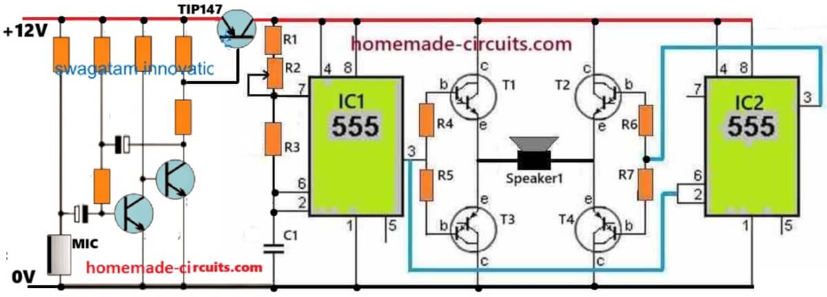
Manual High Power Push-Pull Dog Repellent Circuit (Tested)
The ultrasonic dog repellent circuit shown below is a highly effective design due to its H-bridge configuration, which generates a powerful push-pull action on the attached ultrasonic transducer.
The push-pull mode creates a pumping action on the transducer causing massive thrusts on the generated ultrasonic pulses.
This circuit was practically tried on dogs and cats with positive results. The testing procedure required a lot of hard work and dedicated effort, which was thoroughly implemented by Mr. Emad, who is an avid reader of this blog and great electronic enthusiast.
Circuit Diagram
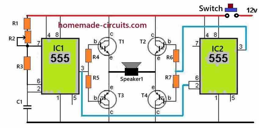
How the Circuit Works
The IC1 is configured as a normal IC 555 astable circuit which generates square wave pulses at its output pin#3.
The resistor R1 along with the R2 pot value determine the frequency of IC1 output.
This output from IC1 is applied to T1, T3 driver transistors of the H-Bridge configuration.
This frequency at pin#3 of IC1 is also fed to the pin2 and pin6 of another IC2 555 stage.
This 555 IC2 is configured as a set-reset circuit, which works efficiently to enable the correct functioning of the H-bridge transistor driver.
The output pin#3 of IC2 is connected with T2, T4 which forms the other set of driver transistors of the H-bridge circuit.
The IC2 ensures that during the ON periods of IC1 pin#3, the IC2 pin#3 is OFF, and vice versa.
This ensures a safe operation of the H-bridge transistors which always operate diagonally, causing an alternate push-pull or reverse forward conduction of the load, which is a transducer in this circuit.
The push pull action of the transducer diaphragm causes powerful thrusts on the generated pulses which ultimately helps to create a strong repelling action on animals like dogs and cats.
Parts List
- R1 = 1k 1/4 watt = 1
- R3 = 4.7k 1/4 watt = 1
- R4-----R7 = 1k 1 watt = 4
- R2 = 20k pot = 1
- Capacitor C1 = 3300 pF Ceramic Disc = 1
- Transistors, T1, T2 = TIP142 = 2
- Transistors, T3, T4 = TIP147 = 2
- IC1, IC2, IC555 = 2
- Push Button 5 amp = 1
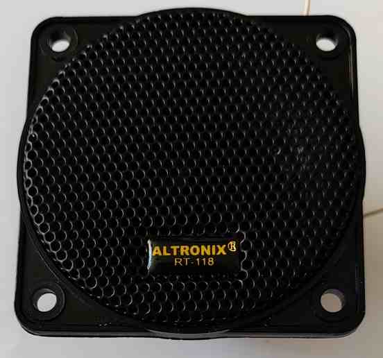
- Speaker1 is a 8 ohm High Power Tweeter, as shown below = 1
Tweeters used in the above prototype
Using Arduino
The above concept can be made even more effective and customizable when built using an Arduino. The complete wiring and circuit diagram is given below:

Below is a simple Arduino code that will generate a square wave with adjustable frequency (1kHz to 25kHz) and output staying ON for adjustable time between 1 to 5 seconds.
Full Arduino Code
const int outputPin = 9;

const int potFreqPin = A0;   // Pot for frequency
const int potTimePin = A1;   // Pot for ON-time duration

unsigned long halfPeriod;    // Half of square wave period in microseconds
unsigned long onTimeMs;      // How long to output the square wave
unsigned long offTimeMs = 1000; // OFF time fixed to 1 second (can also be made variable)

void setup() {
  pinMode(outputPin, OUTPUT);
  pinMode(potFreqPin, INPUT);
  pinMode(potTimePin, INPUT);
  digitalWrite(outputPin, LOW);
}

void loop() {
  // Read and map potentiometers
  int freqRaw = analogRead(potFreqPin); // 0 to 1023
  int timeRaw = analogRead(potTimePin); // 0 to 1023

  int freq = map(freqRaw, 0, 1023, 1000, 25000);         // Frequency: 1kHz to 25kHz
  onTimeMs = map(timeRaw, 0, 1023, 1000, 5000);          // ON-time: 1s to 5s
  halfPeriod = 1000000UL / (2 * freq);                   // Half-period in microseconds

  // Generate square wave for ON duration
  unsigned long startTime = millis();
  while (millis() - startTime < onTimeMs) {
    digitalWrite(outputPin, HIGH);
    delayMicroseconds(halfPeriod);
    digitalWrite(outputPin, LOW);
    delayMicroseconds(halfPeriod);
  }

  // Output OFF period (fixed 1 second or customizable)
  digitalWrite(outputPin, LOW);
  delay(offTimeMs);
}
Code working Details:
- Only one output pin#9 will generate the square wave pulses.
- Frequency adjustable from 1kHz to 25kHz using one potentiometer.
- Pulses will turn ON and OFF intermittently with ON-time adjustable from 1 to 5 seconds using another potentiometer.
- During OFF time, the output pin will remain LOW.
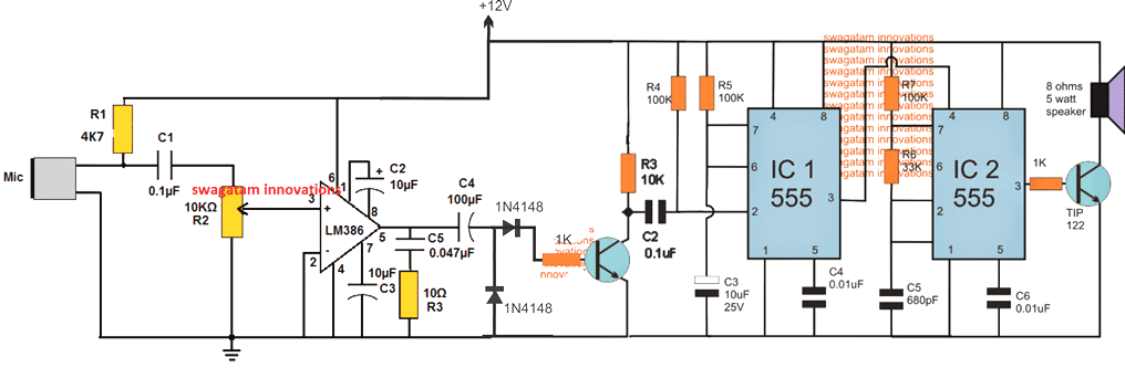
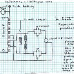
Automatic Dog Bark Terminator Circuit
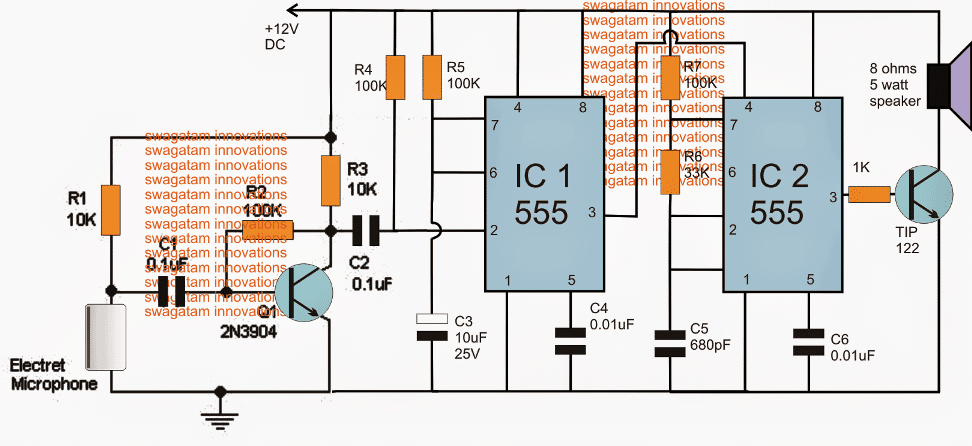
Note: Please use 1uF capacitor for C2 to ensure a foolproof triggering of the IC1 stage...
Parts List
- Resistors all 1/4 watt 5%
- R1, R3 = 10K
- R2, R4, R5, R7 = 100K
- R6 = 33K
- R7 = 1K
- Capacitors
- C1 = 0.1uF, disc ceramic
- C2 = 1uF/25V
- C3 = 10uF/25v
- C4, C6 = 0.01uF ceramic
- C5 = 680pF ceramic
- Transistors
- Q1 = 2N3904 or BC547
- Q2 = TIP122
Referring to the above shown dog bark inhibitor circuit, we can see three distinct stages involved, the sound sensor and preamplifier circuit using the Q1 and the electret MIC stage, the monostable stage using IC1 and the associated parts and the ultrasonic sound generator stage using the IC2 and the speaker driver stage.
Whenever a dog barks, the Mic detects it causing a sequential low and high pulse at the base of T1. T1 responds to this and produces an equivalent amplified signal across C2, which in turn triggers the pin#2 of the monostable IC1.
The above action forces IC1 to produce a high at its pin#3 for a period determined by the values of R5/C3.
This high at pin#3 of IC1 enables the reset pin#4 of IC2 to become active thereby allowing the astable IC2 to supply the ultrasonic pulse at its pin#3, which is appropriately amplified by the associated TIP122 transistor, driving the connected speaker.
The speaker vibrates at the specified amplified level throwing the ultrasonic sound in the direction where the dogs need to be driven away.
The above sound waves is supposed to fluster the dogs and cause a lot of disturbance in their ears due to its high pitched sound, and also due to its synchronized effect with the dog's own barking sequence.
Actually the above dog barking stopping device might respond to all types of high dB sound levels, however since it won't be audible to a human ear this will never be an issue, and may be ignored.
Making the Circuit more Sensitive
If you find the above dog barking prohibitor circuit not responding to barking signals or any sound distant signals correctly, then you must try upgrading the MIC stage with an IC based MIC amplifier stage as shown in the following image:
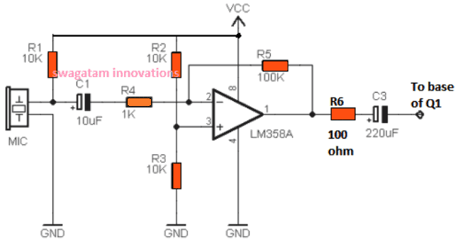
Once you build the above circuit, you can eliminate or remove R1, R2, C1 from the first circuit, and replace it with the mentioned op amp based MIC amplifier circuit and configure the C3 output from the op amp with the base of Q1.
This upgrade will ensure that the circuit responds appropriately even to weak sound signals, specifically dog barking sound during night time, and trigger the IC 555 stages for the intended results.
Increasing the Range over 50 Meters
To make the above design respond to dog barks at distances over 50 meters, the following modified idea could be tried.
However this circuit being extremely sensitive could get triggered by other forms of sounds in the vicinity.
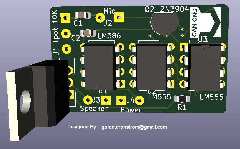
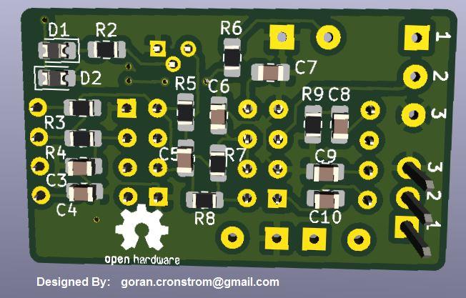
PCB Design
UPDATE: A Much Simplified Design
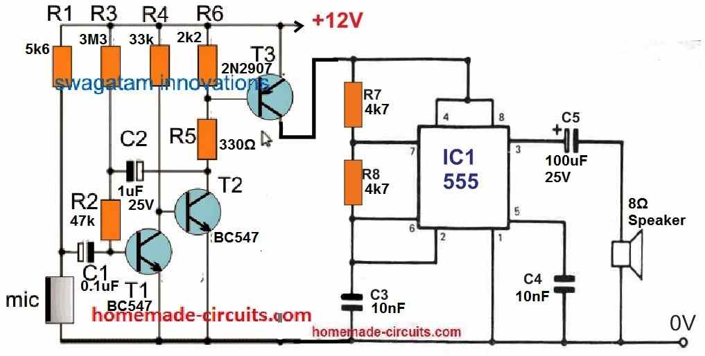
A simple transistorized circuit presented below can be used as effectively as the above designs for repelling dogs or any other animal away, from a distance.
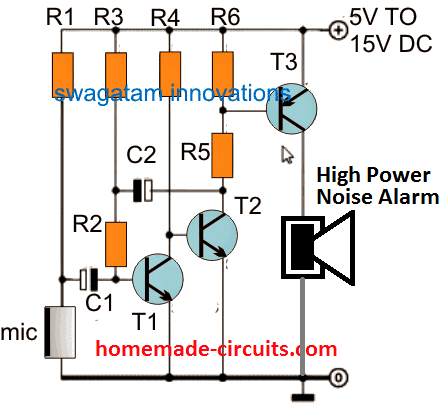
The parts list for the above design is shown below:
- R1 = 5k6
- R2 = 47k
- R3 = 3M3
- R4 = 33K
- R5 = 330 OHMS
- R6 = 2K2
- C1 = 0.1uF
- C2 = 1uF/25V
- T1, T2 = BC547
- T3 = TIP127
- D1 = 1N4007
- Mic = electret condenser MIC.
If you wish to use some other form of deterrent instead of the indicated high power alarm, you can replace the speaker with a relay and connect the desired load with the relay contacts. The relay based design is demonstrated in the following diagram:
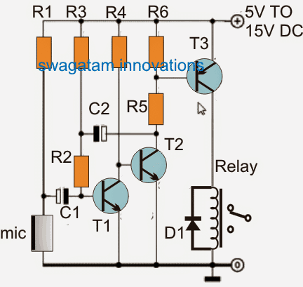
The parts list will be the same as above, except the T3, which can be replaced with BC557 transistor.
How it Works
As soon as a relatively loud noise such as a dog barking sound is detected by the MIC, the signals are amplified by the subsequent BJT stages, which activates the relay momentarily. This momentary delay of the relay activation is determined by the value of C2, which can be adjusted to best suit the application.
The relay contacts can be hooked up with a suitable high frequency circuit, such as an electronic dog whistle.
Improving Further
In the above design, the relay can be eliminated, and the T3 collector output can be directly used to activate the IC 555 frequency generator circuit, as shown in the following figure:
Dog Deterrent Circuit
Are dogs from the neighborhood constantly digging up your front lawn? The following high-pitched screamer can effectively deter them!
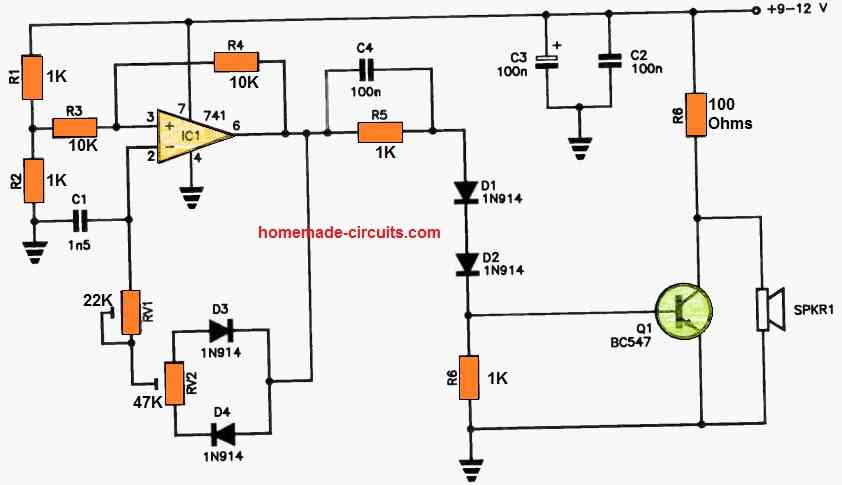
The IC1 (Integrated Circuit 1) is configured as a high-frequency oscillator, producing narrow pulses. You have the flexibility to adjust the frequency using RV1 and fine-tune the mark-to-space ratio with RV2.
IC1's output is channeled to the base of Q1 through R5 and D1-D2. The pulses at the collector of Q1 drive SPKR1, which is a piezo horn tweeter.
These sounds operate at frequencies well above our hearing range and are exceptionally loud, making them audible to dogs and other garden pests with four legs.
The inclusion of diodes D1 and D2 serves to enhance the turn-on voltage for Q1 because IC1's output doesn't reach all the way down to zero volts.
To achieve the best results, some trial and error with RV1 and RV2 settings may be necessary to optimize the device's performance.


Questions & Answers
Hello Swagatam,
Is the tested 1st circuit be able to reach dogs at a distance of 20 mts or 30 mts? If not, how can I improve its reach?
Hello Marcello, first diagram was tested by Mr. Emad.
For 20 meters I would suggest you to reduce the frequency to maybe 9kHz, so that it becomes like a sharp hissing sound (sharp white noise), which may be slightly audible to human being…and this can be reduced by using a cone type radiator around the speaker. Instead of tweeter, try a standard 8 ohm 5 watt speaker….
Remember this must be turned on, only when the dogs bark, and not continuously…
Hello Swagatam, thanks for your quick reply!
Pls did you receive any feedback from Mr. Emad if the dogs just stop barking or they run away desperately or both?
Hi Marcelo, since the testing was done successfully once, so maybe Mr.Emad did not not find it necessary to update further results.
The 1st circuit should work above 20 meters if the frequency is reduced to audible range of maybe 12kHz, and directed through a conical radiator…
Hello Swagatam,
Thanks for your prompt feedback!
Before I starting to build the circuit, I was just wondering for a final confirmation from someone else who really tested it against the dogs and what was their behaviour in such distance (20 ~ 30 mts).
Marcelo, if you build it correctly, as explained by me in the previous comment, then it should work as per the expectations…
Perfect! Will do.
Thanks, Swagatam!
You are welcome, let me know if you face any further issues…
Hi. my neighbors have dogs that barks most of the time — early mornings, mid morning, noon time , afternoon and evening when I am watching some movies–less frequent. I am considering to build one of your electronics designs but I want to know if this circuit will also scare other animals that visit my property for foods like monkey, lizards, skank, possums, etc. , which I welcome and feed them and I want to keep them around. So, I just want to stop the dog from barking. Recommend a circuit?
Yes, most likely this circuit will scare most of the other animals also…
You can try a manual dog whistle in front of monkeys and check whether or not they are scared, that will prove if the above circuit can affect other animals or not…
Hi. I just built the circuit as described at the beginning of this article. I noticed that the transistors get hot after a few seconds so I will mount them on a heatsink — T2 get overheated much faster than the others transistors. Somewhere in your comments, you advise someone to use a 10mf capacitor with a tweeter so I need to confirm if this capacitor is to be mounted in parallel or in series with the tweeter? I do not have any instrument to check its frequency so I am using my iphone app to check its frequency. As I move the pot from one end to the other , its frequency output change erratically from low 300 to 18500hz but it does not stay fixed at its peak of 18500 hz approximately and also it does not reach 20000 or higher. What can cause that? Also, its propagation frequency does not goes beyond 4 – meters unless I place the tweeter inside of a 2 1/2″ tube — I would like to extend its frequency range to 20 to 30 meters. I really appreciate your help on those things that I am having some concerns. Thank you
Hello Alex. Pls I’m interested to see the results of your efforts. Let’s get in touch.
Hello Alex,
I’m facing the same nightmare with dogs in my region…I really need a powerfull and effective circuit that really disturbs the dogs at 20 to 30 mt range. Please, have you made the circuit yet? Any success? I’m from Brazil.
Hi, the 10uF capacitor, it has to go in series with tweeter, the capacitor mainly blocks the lower frequencies and lets the higher frequencies pass.
About the transistor heating especially T2, it usually happens from too much current or maybe some wiring mistake somewhere, so check the transistor pin connections once again carefully because even one wrong pin can make transistor heat very badly.
Also check whether R4/R5 and R6/R7 values are exactly correct or not.
Use only 8 ohm tweeter here, lower impedance ones may pull extra current and then transistors become hot very quickly.
Small heatsinks on all transistors will help too.
That unstable frequency reading is not very surprising actually, phone apps above 18kHz are usually not very trustworthy, moreover ordinary tweeters also start becoming weak near ultrasonic range, so around 20kHz the reading may keep jumping a little instead of staying fixed.
That 4 meter range also looks kind of normal with ordinary tweeter setup.
If longer range is needed then better try piezo ultrasonic tweeter or transmitter type unit.
A horn or tube in front may help focus the sound more forward.
Keeping frequency somewhere around 17kHz to 19kHz usually works better for propagation instead of pushing too near 20kHz and above.
Power can be increased carefully, but then heatsinks become more important otherwise transistors may overheat again after some time.
For reaching maybe 20 to 30 meters powerful directional ultrasonic transmitter setup is needed, normal tweeter based circuits may not work…
Thank you for your kindly reply.
Hello Swagatam,
I came to this post very late after buying XY-LPWM Signal Generator PWM & Multicomp Pro 16mm 40kHz Ultrasonic Transceiver Black -74dB with 2N3904 & 1k registor however i failed to generate the audiable sound out of that circuit. I placed 5V and tried with 12v too but no luck.I set PWM to generate 1k, 10K also tried 100 hz etc but no audiable signals on the Ultrasonic Transceiver.
would you suggest the how I could generate at least 20Khz or 40Khz from above componants.
Hi Yogesh,
How did to wire the 2N3904 base, collector, emitter with the module and the transducer? And what duty cycle (PWM) did you fix in that module? Please let me know about all these, I will try to figure it out for you…
Initially you can try replacing the transducer with a headphone and check the response at lower frequencies below 10kHz, and PWM at around 50%…if you hear the tone, that will prove the module is working correctly….
The VIN+ and GND pins of the XY-LPWM module to your power supply (e.g., 5V).
Connected the PWM output pin of the module to the base of the NPN transistor via a 1 kΩ resistor.
Connected the emitter of the NPN transistor directly to GND of the power supply.
Connected one terminal of the piezo speaker to the positive power supply line (e.g., 5V).
Connected the other terminal of the piezo speaker to the collector of the NPN transistor.
I tried 100 khz then 1khz and 20, 40 khz but no sound from passive piezo speaker ( which supports 40khz at 98db)
Your connections look good…
However, a transducer will not generate an audible sound like a normal speaker…
So, to confirm you can connect a headphone or a small 8 ohm speaker in place of the transducer, and check the results…make sure to connect a 100 ohm resistor in series with the 8 ohm speaker so that the transistor does not heat up…
Possible to get circuit from you directly? I need to generate 40khz to 100khz frequency by changing the Potentiometer. Possible? I will be using 12V battery
Sorry, nowadays I do not sell components or kits, so it might not be possible to get them directly from me.
Hi, dear.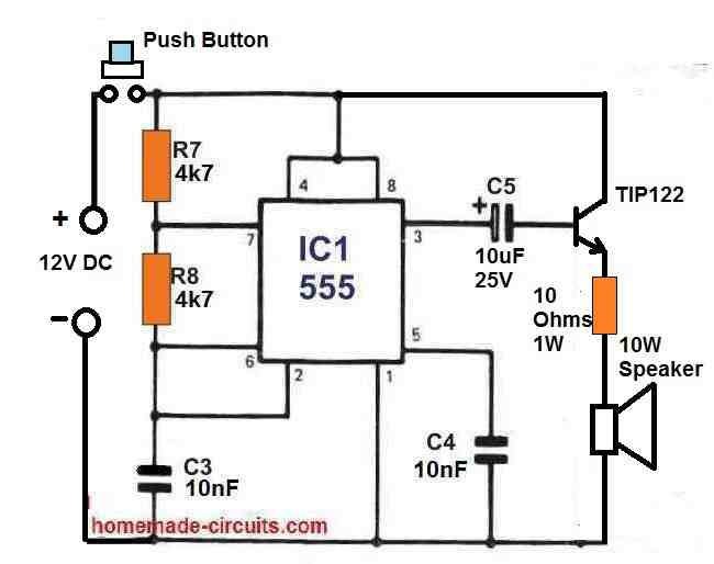
I made this circuit:
The problem is that the 10R 1W resistor and TIP122 gets very hot after a few seconds of operation, I use a single 10W 4ohms speaker or 2 speaker 10W 4ohms in series (10W 8ohms).
Hi, Thanks for your kind feedback….Please try replacing the transistor with a TIP35, and resistor with 10 ohms 5 watt wire-wound, and check the response…
Hi Swagatam;
Re. to above high power push-pull dog repellent circuit, sorry but i have a doubt for the transistors connection. For instant, tip142 is NPN type transistor, so if the base is + then either the emitter or the collector should be connected to the negative side in general usage. Then this is the exceptional usage or there is any mistake on the circuit diagram?
Suat, the NPN transistor in this H-bridge network is working like an emitter-follower, and the speaker becomes its emitter load, then the other side PNP BJT keeps the other wire of the speaker grounded, so the conduction completes, so the H-bridge design is correct.
i am so sorry Swagatam but i have not mentioned neither the emitter follower or the collector follower matter, i have meant that the location of the T3 and T4 would be changed with the T1 and T2 in accorance with their PNP or NPN type specification, thanks again.
Suat, Do you mean, swap the NPN with PNP and vice versa? Yes definitely that is also possible, and can be tried.
Hi Swagatam;
Re. to above high power push-pull dog repellent circuit, i need your confirmaton for the followings;
1- if the emitters and collectors connections of the transistors are OK? or can we connect them as the reverse connected?(changing the emitter and collector side reverse)
2- if it is necessary to use a capacitor with the speaker or not?
Hi Suat,
It is possible to modify the H-bridge pinouts of the BJTs but i won’t recommend that because the given configuration is a tested design, so it is better to stick with this design, moreover the present configuration is good and reliable.
Yes you can add a series capacitor with the speaker, maybe a 10uF non-polar capacitor for adding extra safety for the speaker and the transistors…
Hi Swagatam;
i made a programme that produces 26 KH, 22 KH and 20 KH frequencies or PWM signals. Their duty cycle rates are 50%, 60%, 80% and each session lasts 3,5 seconds. For instant 20 KH frequency with the duty cycle 60% runs 3,5 seconds then the other runs in the same period. My Oscilloscope displays and confirms that all output signals are OK. For the test purpuse use 2,2 mF capacitor and the 8 Ohm 0,5W speaker. The distance between the dogs and the circuit is about 1 meter. But the dogs do not show any reflection. Even they do not move. Could i have your opinion on the matter?
Hi Suat,
Then I think it is better to make the 555 version first and test it practically, because it was tested by Mr. Emad successfully.
If it works then you can replicate it with an Arduino…but then the H bridge must be correctly bult and should be compatible with Arduino outputs.
thanks for the support, is it possible to use bd135, bd136 or tip31, tip32 instead of the tip142 and the tip147?
Yes, that’s possible. In that case you can reduce the base resistor values to maybe 200 ohms.
Hi Swagatam;
Re. to above 555 or ardunio circuits, is it possible to use HBridge with the irfz44n instead of the bd139/140 and / or tip142/147 type transistors?
Hi Suat, a BJT will drop only around 1V at its emitter terminals, while a MOSFET might drop upto 5V, so that is the difference between the two types of devices according to me, when they are configured as emitter followers or source followers..
Hi Swagatam,
Looking at the push pull dog deterrent circuit, I see you are using TIP35 & TIP 36. According to your diagram they are darlington pairs,is this correct as TIP 35&36 are NPN and PNP transistors?
Can you please clarify.
Jim
Thanks Jim, Actually TIP35 and TIP36 are not Darlington, I have corrected the parts list now, and replaced them with TIP142 and TIP147, please use these BJTs for optimal performance…
Hi Swagatam,
Thank you for great circuits.
I would like to add a mic to the manual push pull circuit, is that possible?
Kind regards
Jim
Hi Jim,
here’s the automatic version of the 555 H-bridge design you are looking for…let me know if you have any further doubts or questions:
Hi Swagatam;
i have produced some low level pwm signals for the test purposes and published short video in the youtube(https://www.youtube.com/shorts/s0ttnyUXQsg) and i used 8 ohm 0.250A speaker to check the output signals. As it can be seen that there is no H-Bridge system but only one 220 uF capacitor between the pwm output pin and the speaker.
Now i will try the frequencies between the 5K and 25K.
i can apply 5V or 9V to the audio / speker side so could you please help me on the matter that should i prefer the polarized or non polarized capactor before the speaker and its ideal uF value? Or please advice if HBridge system is must since the frequency is high?? Or this is the relevant with the dog and the circuit distance.
Hi Suat, the H-bridge configuration is a must, and it plays key role to make the design so effective.
Without H-bridge the circuit might be just 50% effective and the range could be highly compromised.
So yes, H-bridge stage is a must…and I would advise you to first try the 555 version and check its performance in a real life situation, possibly in an ethical way.
Many thanks Swagatam, I see the advantage of the H-Bridge but I really did not understand about the ethical way could you please explain?
You are welcome Suat! By ethical treatment, I mean, to consider the animal situation also, if it is sick or sleeping then please do not test on them, if it is in normal situation then you can test the unit, maybe for a few seconds from a distance.
be sure i love them too much and i really think the same also every morning i try to fed them it may be necessary just for the children.
Same here Suat! I also love them a lot. So glad to know you feed them every morning, that is really heart-touching. And yes I agree, it also teaches the kids something really good.
some kids were killed here by the dog flock attacks since there are too many unleash/vacant dogs here and some times they are too dangerous esp. at the deserted streets in the early morning or late at nights.
For street dogs the above circuit can be used freely, since the dog has the freedom to run away, but it is not advisable for dogs who are confined inside a fenced area or house…
Hi Swagatam;
Re. ardunio circuit, i exclude the ardunio side loop but just test the H Brigde side i mean there is no pwm no voltage at the base of BC547, the source voltage is 12V and the current is about 1,3A whle the circuit is off. Meanwhile i have used bd135 bd136 Could you please share your opinion if the current ratio is natural although there is no trigger voltage of the BC547?
Hi Suat,
If you keep the input of BC547 open, then the H-bridge will start behaving abnormally and might cause a short circuit across the transistors.
So if you want to test the H-bridge without the Arduino, then you must add either a +5V or 0V logic at the base of the BC547, and then test it.