Rats are a dreaded pest that may ruin houses, gardens, and other places. They harm furniture, electrical lines, and other objects in addition to being carriers of a number of illnesses. It makes sense that people would constantly seek for strategies to keep rats out of their gardens and houses. Using a circuit that repels rats is one efficient method to do this.
An electrical device that creates high-frequency sound waves that are unpleasant to rats is known as a rat repellent circuit. While these sound waves are inaudible to people and other animals, they have a powerful deterrent impact on rats. This article will go over the construction and operation of a rat-repelling circuit.
Components Required
To build a rat repellent circuit, you will need the following components:
- 555 timer IC
- Resistors (1KΩ, 47KΩ)
- Capacitors (0.1µF, 0.001µF for CT)
- Piezoelectric buzzer
- BC547 transistor
- 12V or 9V battery
- Connecting wires
- Piezo Transducer
Circuit Diagram
The circuit diagram for a rat repellent circuit is shown below:
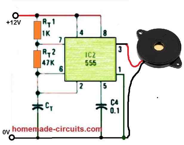
How it Works
The rat repellent circuit uses a 555 timer IC as an astable multivibrator. The 555 timer is configured to produce a square wave with a frequency of about 15 kHz. This frequency is almost beyond the audible range of humans but is within the hearing range of rats. The 555 timer is connected to a transistor that amplifies the signal and drives a piezoelectric buzzer.
The piezoelectric buzzer converts the electrical signal from the transistor into high-frequency sound waves. These sound waves are unpleasant to rats and can drive them away from the area. The sound waves are directional, so it's important to aim the piezoelectric buzzer towards the area where rats are present.
The rat repellent circuit is powered by a 9V battery. The battery is connected to the circuit through a switch that can turn the circuit on and off. The circuit can be easily built on a breadboard, and the components can be easily obtained from electronic stores.
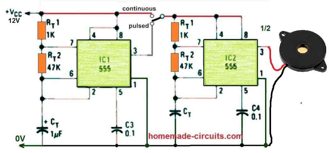
A More Effective Circuit
The above explained circuit might produce a continuous 15 kHz frequency which sometimes not be effective enough to rattle a rat.
In order to make the circuit more effective, we can make the above design in the pulsed form. In pulsed form the 15 kHz frequency will be transmitted in the pulsed mode causing more disturbance to the rat. This increased disturbance will ultimately cause the rat to run away or vacate the place quickly.
The complete circuit diagram for the pulsed rat repellent circuit can be seen in the following figure.
How to Use
Using a rat repellent circuit is easy and straightforward. Once you have built the circuit, you can follow the steps below to use it:
Find the area where rats are present: The first step is to identify the area where rats are present. This could be in your home, garden, or any other area where rats are causing a problem.
Place the circuit in the area: Once you have identified the area, place the rat repellent circuit in a central location in the area. It's important to ensure that the piezoelectric buzzer is aimed towards the area where rats are present.
After the circuit is installed, you may turn it on by turning the switch. Rats won't like the high-frequency sound waves that the circuit will begin to generate.
Track the outcomes: Watch the results and keep an eye on the region where the circuit is located. You ought to observe a decline in the local rat population over time. It's crucial to keep in mind that the circuit's performance may vary depending on a number of variables, including the area's size, the presence of rats, and the circuit's placement.
Maintain the circuit: To make sure the circuit is functioning correctly, it is crucial to frequently examine and maintain it. This can entail making sure the parts are properly connected, cleaning the piezoelectric buzzer, and checking the battery.
Advantages
A rat repellent circuit is an electronic device designed to deter rats and other rodents from entering or staying in a particular area. Some of the advantages of using a rat repellent circuit include:
Rat repellent circuits are a cost-effective solution to a widespread issue since they are reasonably inexpensive to construct or buy and require very little upkeep.
Safe and humane: Rat repellent circuits are designed to repel rats without harming them, making them a safe and humane alternative to traditional rat traps or poison, which can injure or kill rodents.
Rat repellent circuits are a safe substitute for conventional pest management techniques that might hurt people or pets because they don't contain any poisonous chemicals.
Rat and other rodent repellent circuits may be quite successful at keeping them out of a space. They produce unpleasant high-frequency sound waves that drive rats away from the area.
Rat repellent circuits are simple to install and may be utilised in a range of locations, including indoor and outdoor areas of buildings as well as private residences.
Rat repellent circuits are normally made to last a long time; some versions have a lifespan of up to 10 years, offering a long-term solution to rodent issues.
In conclusion, rat repellent circuits provide a risk-free, economical, and compassionate approach to keep rats and other rodents off your property.
Conclusion
The best approach to keep rats out of your house or yard is with a rat repellent circuit. Although inaudible to humans, high-frequency sound waves are unpleasant to rats. A rat-repelling circuit is simple to construct and only needs a few parts. You may create your own rat repellant circuit and keep rats out of your house and yard by following the diagram and directions in this article.

Questions & Answers
Hi,
Thank you for the excellent website.
We currently have a big problem with rats where I live. A building site nearby seems to have disturbed their habitat and they gave moved into the gardens and outbuildings of the houses nearby – in large numbers. I have built a small device with a piezo disk and a 555 – but I am unsure how effective it is. It maybe works over a short distance, but We still seem to have a lot of rats. I want to use some piezo tweeters which I used for a public address system years ago. I have about four of these and they are capable of being very loud – but a conventional amplifier is unlikely to be effective above 20khz or so. I have thought of using a transformer to get a high voltage from a simple power transistor (the tweeters could maybe handle up to 100v pk to pk?) but a conventional iron core transformer for 50hz is also unlikely to be good at ultrasonic frequencies and I can’t find a suitable ferrite core component. I am going to try to design and build a ‘wide area’ rat deterrent device as soon as I can, but I would welcome any ideas or suggestions. It is driviing the tweeters at high output at 20 to 50 KHz that I am struggling with. Many thanks.
Hi, thanks for your interesting question.
In that case you can try building the following boost converter circuit. The output diode, capacitor, resistor could be eliminated, and the transducer could be connected directly across the inductor. For calculating the parts you could use these calculators.
https://www.homemade-circuits.com/ic-555-boost-converter-calculator/
https://www.homemade-circuits.com/ic-555-timer-astable-circuit-calculator/
Thanks for your reply and the suggestions. I have today ordered a ferrite core and bobbin so I can wind an inductor. I will try out the circuit and do sone experiments and let you know how it works out.
Sounds great! Thanks for your feedback. Let me know if you face any problems with the circuit.
Also why is the sound so unplesant to humans itself
can we replace the 1k and the 47k resistor with a potentiometer to vary the frequency
You can put a 100k pot in series with the 1k resistor, and replace the 47k resistor with a 47k pot.
Please provide a good dog repellent circuit effective for about 100 meters.
Can I use 12 volt AC to DC adapter for continuous supply of voltage
Yes you can!
I have begun researching electronic parts and I really miss Radio Shack.
Do you have a source for the items used in your projects?
I am very glad I found this (you) source of information and the explanations given.
My background was bio medical equipment at the beginning of the Z80 , and all my work was with a 35mhz oscilloscope, lol that was fast in 1980.
No problem, I am always glad to help.
You can easily get the parts from any online spare part dealer.
You just have to type the part number and add the word “buy” with it, you will be able to find many good options from where you can procure the parts.
The easiest way is to get them from amazon or Ebay.
I have tried looking for the transistor that is called out in the parts list.
Can you identify the location and pins location, please?
Also what is their switch part number? And what makes it pulse?
Is that the transistor?
Sorry for the confusion, you can ignore the transistor BC547 since it will not be required in the above circuits.
If you need more amplification, you can use a 2n2222 transistor at pin#3 of the IC 555 and add the buzzer at the collector of the 2N2222.
There are no transistors in the above circuits, all are IC 555
Can a low battery led be added! If so how?
For low batt indication, you may have to include the following circuit:
https://www.homemade-circuits.com/low-battery-indicator-circuit-using-two/
Hi
I have not found the connection to IC with Piezo Transducer. Could you please ass those to the circuit diagram.
Hi, yes you can them as shown in the diagram.
Is it any video on this
Video is not there, but logically this circuit will work 100% without fail.
Thank you very much
Can I use single 556 ic inplace of two 555 ics
Yes you can, no problem.
Good morning Mr.swagatam ,
Thanks for the prompt reply. Really, I appreciate your help
You are welcome BLV.
how can I get the PCB for this ? Do I need to design ?
Please first test it by assembling on a perfboard, if it works only then go for a PCB. A professional PCB designer will get it done for you.
But you told this will work. Right.? Then we can go for direct assembling in PCB.
The last circuit will work, but still it needs to be verified practically. You don’t need to test it with real rats, you just have to verify whether the circuit generates intermittent pulsed noise or not by experimenting with Rt and Ct. This circuit needs to be tweaked perfectly to get ideal results.
Remember you must do it with proper understanding, if you do without understanding then you might have problems.
Thanks. Will share the results with you.