• Skip to main content
  • Skip to primary sidebar

Homemade Circuit Projects

Get free circuit help 24/7

Circuits for Beginners | Basic Circuits | LED Driver | Hobby Circuits | Transistor Circuits

New-Projects | Privacy Policy | About us | Contact | Disclaimer | Copyright

Home » Home Electrical Circuits » Solar Insect Killer Circuit for Protecting Crops in Farms

Solar Insect Killer Circuit for Protecting Crops in Farms

Last Updated on July 6, 2019 by Swagatam 2 Comments

The insect killer circuit presented here is designed to attract insects during night, and electrocute them through a high voltage mesh trap. The unit can be installed in farms for protecting crops from potentially harmful insects. The unit being solar powered does not depend on human intervention and works independently.

In one of our previous posts we came across a simple mosquito killer circuit which Incorporated a high voltage electrocuting device for killing the mosquitoes, here too we apply the same principle for terminating the potential insects using a high voltage mesh trap.

Insect Trap Set Up

The following image shows the basic set up that needs to be fabricated and installed within a farm for implementing the insect control actions.

The shown set up indicates a solar panel placed at the top of the structure, the high voltage collector mesh can be seen clamped vertically just below the solar panel, while a LED can be witnessed positioned beside the mesh trap.

The battery and the circuit are enclosed inside a wooden "house" like structure which becomes the base for all the above described fabrications.

The slanting roof of the house shaped cabinet ensures that the insects slide and fall down on the ground while they hit the mesh and get killed.

The bulb is used for attracting the insects, as we all know that any form of light attracts insects towards it and the same principle works here for luring the insects near the high voltage mesh trap.

The bulb could be either an LED lamp, a low wattage CFL lamp or even a black light or an UV wood's lamp.

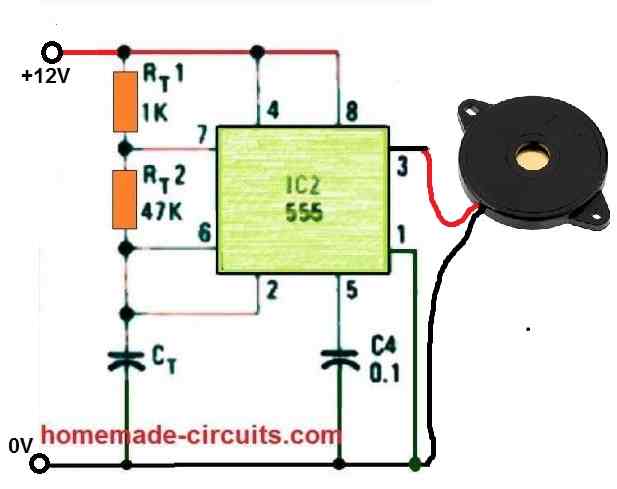
High Voltage Generator

The high voltage generator circuit is the same which was explained in our previous post, the 22k pot may be used for adjusting the electrocuting arc power such that the spark are strong enough and arc only in the presence of an insect within the mesh, and stay dormant otherwise.

The output from the above linked high voltage generator (CDI coil) is supposed to be integrated with the below shown mesh trap design:

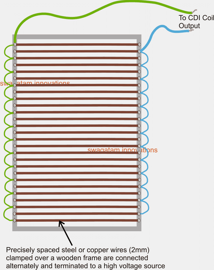
Making the Electrocution Mesh

The electrocutor mesh trap is made by attaching stiff steel or copper wires inside a sturdy wooden frame, in the above shown manner...the wires are then alternately connected using small pieces of connecting wires.

The common ends of the two alternately arranged mesh assembly is then terminated to the CDI coil or the high voltage generator.

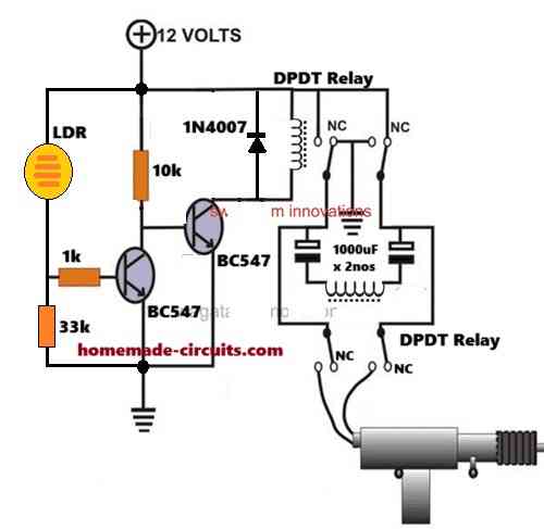
Since the battery used for powering the high voltage generator needs to charged with a solar panel, a simple solar charger circuit becomes imperative, the same may be built exactly as instructed in the following article

https://www.homemade-circuits.com/2012/04/how-to-make-solar-battery-charger.html

The ammeter may be eliminated as it's not so important for the present application.

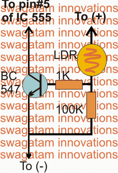
There's another issue that needs to be solved here, the high voltage generator circuit needs to remain switched OFF during the day time while the battery is being charged.

This may be implemented by adding the following simple transistor/LDR circuit with the pin#5 of the IC 555 of the high voltage generator stage.

You'll also like:

  • 1.  How to Build an Ozone Water/Air Sterilizer Circuit – Disinfecting Water with Ozone Power
  • 2.  Emergency Generator Circuit Power Distribution
  • 3.  How to Make Dog Barking Preventer Circuit using High Frequency Deterance
  • 4.  Simple Hobby Circuit Projects
  • 5.  DC Lamp Dimmer Circuit using IC 555
  • 6.  Transformerless Relay Driver Stage

About Swagatam

I am an electronic engineer (dipIETE ), hobbyist, inventor, schematic/PCB designer, manufacturer. I am also the founder of the website: https://www.homemade-circuits.com/, where I love sharing my innovative circuit ideas and tutorials.
If you have any circuit related query, you may interact through comments, I'll be most happy to help!

Subscribe2


Reader Interactions

Comments

    Your Comments are too Valuable! But please see that they are related to the above article, and are not off-topic! Cancel reply

    Your email address will not be published. Required fields are marked *

  1. isidro says

    Dear friend Swagatam: in the circuit, the colector (BC547) go to the pin 4 (reset) (LM555), no to the 5 (voltage control), ¿or no? Saludos desde México.

    Reply
    • Swagatam says

      Dear isidro, pin5 is correct, but pin4 will also work if the pin4 is connected with 10k to positive.

      Reply

Primary Sidebar

Categories

  • 3-Phase Power (15)
  • 324 IC Circuits (19)
  • 4017 IC Circuits (53)
  • 4060 IC Circuits (25)
  • 555 IC Circuits (98)
  • 741 IC Circuits (19)
  • Amplifiers (58)
  • Arduino Engineering Projects (82)
  • Audio Projects (94)
  • Battery Chargers (82)
  • Car and Motorcycle (94)
  • Datasheets (46)
  • Decorative Lighting (Diwali, Christmas) (33)
  • DIY LED Projects (89)
  • Electronic Components (97)
  • Electronic Devices and Circuit Theory (35)
  • Electronics Tutorial (109)
  • Fish Aquarium (5)
  • Free Energy (35)
  • Fun Projects (11)
  • GSM Projects (9)
  • Health Related (18)
  • Heater Controllers (28)
  • Home Electrical Circuits (101)
  • How to Articles (20)
  • Incubator Related (6)
  • Industrial Electronics (28)
  • Infrared (IR) (40)
  • Inverter Circuits (98)
  • Laser Projects (12)
  • LM317/LM338 (21)
  • LM3915 IC (25)
  • Meters and Testers (63)
  • Mini Projects (171)
  • Motor Controller (66)
  • MPPT (7)
  • Oscillator Circuits (24)
  • PIR (Passive Infrared) (8)
  • Power Electronics (33)
  • Power Supply Circuits (74)
  • Radio Circuits (9)
  • Remote Control (47)
  • Security and Alarm (61)
  • Sensors and Detectors (116)
  • SG3525 IC (5)
  • Simple Circuits (74)
  • SMPS (29)
  • Solar Controllers (61)
  • Timer and Delay Relay (54)
  • TL494 IC (5)
  • Transformerless Power Supply (8)
  • Transmitter Circuits (40)
  • Ultrasonic Projects (14)
  • Water Level Controller (45)

Circuit Calculators

  • AWG to Millimeter Converter
  • Battery Back up Time Calculator
  • Capacitance Reactance Calculator
  • IC 555 Astable Calculator
  • IC 555 Monostable Calculator
  • Inductance Calculator
  • LC Resonance Calculator
  • LM317, LM338, LM396 Calculator
  • Ohm’s Law Calculator
  • Phase Angle Phase Shift Calculator
  • Power Factor (PF) Calculator
  • Reactance Calculator
  • Small Signal Transistor(BJT) and Diode Quick Datasheet
  • Transistor Astable Calculator
  • Transistor base Resistor Calculator
  • Voltage Divider Calculator
  • Wire Current Calculator
  • Zener Diode Calculator

Facebook
Twitter
YouTube
Instagram
My Facebook-Page
Quora

© 2022 · Swagatam Innovations

We use cookies on our website to give you the best experience.
Cookie settingsAccept All
Privacy & Cookies Policy

Privacy Overview

This website uses cookies to improve your experience while you navigate through the website. Please visit the Privacy Policy Page for more info.
Necessary
Always Enabled
Necessary cookies are absolutely essential for the website to function properly. This category only includes cookies that ensures basic functionalities and security features of the website. These cookies do not store any personal information.
Non-necessary
Any cookies that may not be particularly necessary for the website to function and is used specifically to collect user personal data via analytics, ads, other embedded contents are termed as non-necessary cookies. It is mandatory to procure user consent prior to running these cookies on your website.
SAVE & ACCEPT