The proposed 48 V automatic battery charger circuit will charge any 48 V battery up to an optimal 56 V full charge level, utilizing very ordinary components. The circuit is highly accurate with its over charge cut off features.
Circuit Description:
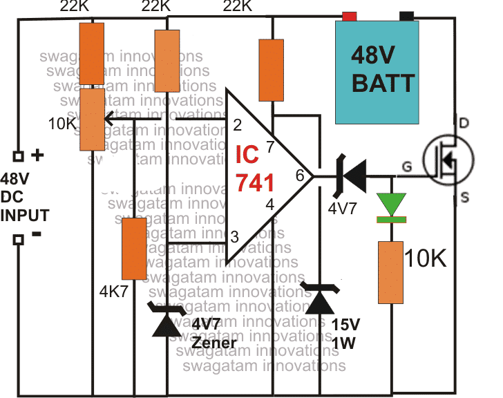
As shown in the circuit diagram, the main element in the circuit is the opamp IC 741, which has been arranged as a comparator.
Pin#3 which is the inverting input of the IC is referenced with a fixed voltage of 4.7V through the respective zener/resistor network.
The other input is applied with the sensing voltage which is actually the voltage merged from the supply and the from the battery, in other words the charging voltage which is applied to the battery for charging.
The resistor network at pin#2 along with the preset forms a voltage divider network which is initially adjusted such that the voltage at this pin stays below the voltage level at pin3, which is the reference voltage set at 4.7v by the zener diode.
The preset is set in such a way that the voltage at pin#2 rises above the 4.7 mark as soon as the battery voltage rises above 50V or the fill charge threshold level of the battery.
The moment this happens, the output of the opamp goes low switching OFF the mosfet, and cutting off the voltage to the battery.
Initially as ling as the battery voltage and the over all voltage from the 48V supply remains below the full charge threshold level of the battery, the output of the opamp stays high and the mosfet us kept switched ON.
This allows the voltage to the battery for charging, until the above explained threshold is reached which automatically inhibits the battery from further charging.
The mosfet can be selected as per the AH rating of the battery.
UPDATE: For converting this into a Solar version you can read this article
1) Using Mosfet Cut Of
2) Current Controlled Version of the above Design
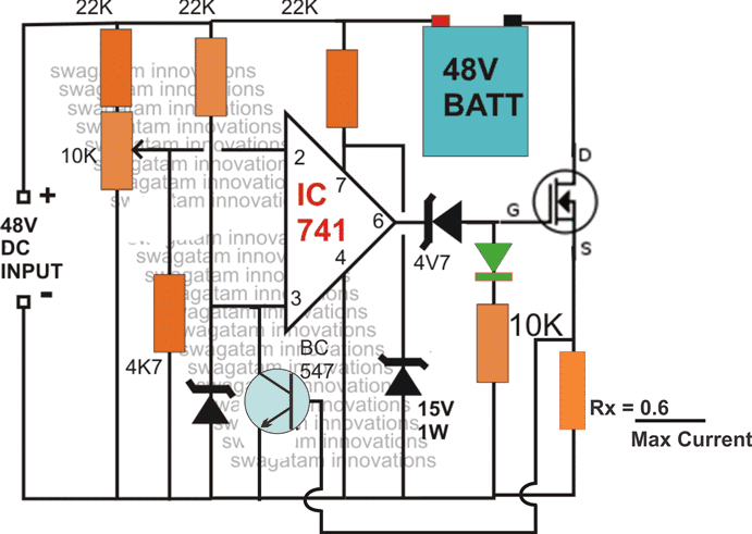
NOTE: The above diagrams mistakenly shows 48V as the input, the correct value is 56V. Because the full charge level of a 48 V battery is around 56/57 V.
NOTE: You will have to connect the battery first and then switch ON the input supply, otherwise the mosfet will fail to initiate for the charging process. Make sure the green LED remains illuminated after power switch ON, this will confirm the charging status of the battery.
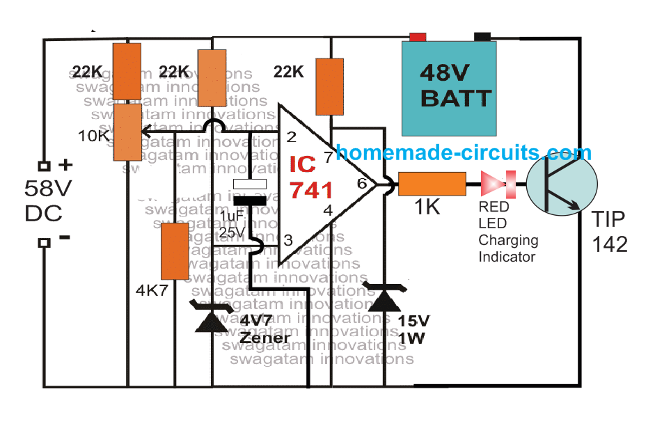
The above design can be also built using a TIP142 and a red led charging indicator.
Simple 48 V 100 Ah charger Circuit using OP Amp and TIP142
3) Making a Fully Automatic Version
The above circuit can be upgraded into an over charge cut off, as well as low charge restoring battery charger system, for charging 48V batteries.
The modifications enables the circuit to switch OFF the battery charging process at the set over charge threshold and restore back the process when the battery voltage falls below the low threshold value.
The 10k preset must be adjusted to set the full charge level while the 22k preset for detecting the lower threshold of the battery.
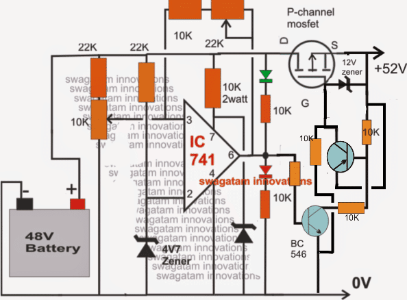
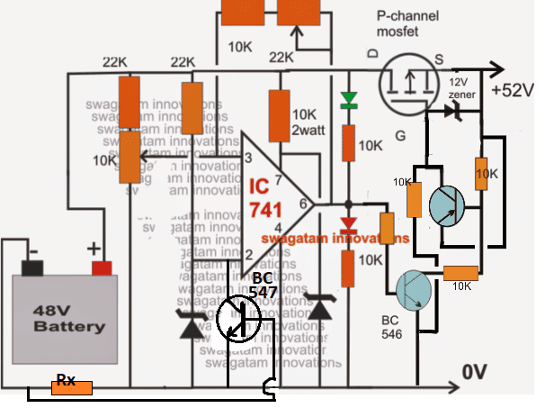
NOTE: In the above two circuits, please connect the RED LED in series with the BC546 base. This will prevent the op amp offset voltage from reaching the BC546 base and false triggering.
Simplifying the Design
The above design can be further simplified as shown in the following image. Notice that the input pins of the op amp are swapped in this design, which allowed the elimination of the extra PNP BJT from the circuit.
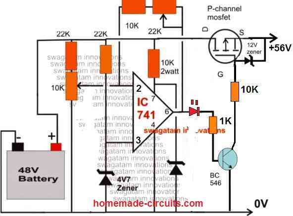
The above circuit can be also built using PNP BJT instead of a MOSFET, as shown below:
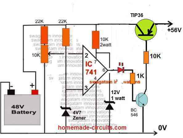
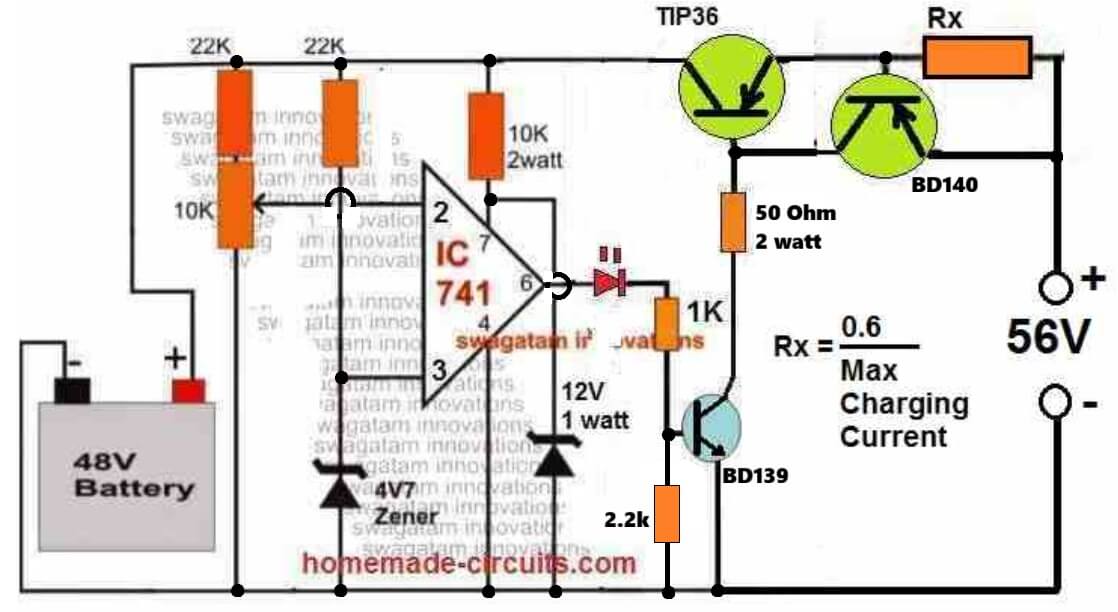
You can also add an current control feature to the above circuit, as shown in the following diagram:
Complete Parts List
- Resistors are all 1/4 watt 5% CFR, unless specified
- 22k = 2
- 10k preset = 1
- 1k = 1
- 50 Ohm 2 watt = 1
- Rx = As per the formula
- TIP36 Base Resistor = (Input Voltage - 0.7) * hFE / Max Charging Current
- Semiconductors
- Zener diode 4.7V, 1/2 watt = 1
- Zener diode 12V, 1 watt = 1
- BJT TIP36 + BD140 = 1 each
- BJT BD139 = 1
- LED RED 5mm, 20 ma = 1
- IC 741 = 1
- Heatsink for TIP36 = 1
How to Set up the above Circuit:
For setting up procedure, the sample power supply should be connected across the points where the battery is connected, the mosfet does not require any attention initially. DO NOT connect the battery while carrying out this procedure.
Also keep the 22k preset link disconnected initially.
Apply the higher threshold level across the above mentioned points and adjust the 10K preset such that the RED LED just switches ON. Seal the adjusted preset with some glue.
Now reconnect the 22k preset link back into position.
Next, reduce the sample voltage to the lower threshold value and adjust the 22k preset such that now the green LED just lights up, while switching OFF the RED LED.
If you find no response from the circuit try using a 100K preset instead of the 22k preset.
Seal the adjusted preset as above.
The setting up of the circuit is over and done.
Please note that during actual operations, the above circuit will remain functional only as long as a battery stays connected at the shown points, without a battery the circuit will not detect or respond.
Feedback from Mr. Rohit
I have a 50-52v solar panel setup which is charging a 48v 78ah battery. What I want is when my battery is fully charged that is it reaches to 54v the battery charging stops and the supply which is coming from the solar panels is directed to another port from which we can charge any other device connected to the port. This charging should only continue till the battery is above 48v. Once it reaches 48v the battery again starts charging on solar panels and the supply to the other port is stopped.
Hoping you will reply soon.
My Response to the above Circuit Request
You can try the last circuit from the following artcilehttps://www.homemade-circuits.
Regards


Questions & Answers
Good evening Sir,
1) I want to use the last circuit as a solar charge controller. Input voltage from solar panels will be between 360VDC to 450VDC.
What modifications can I do?
2) I can not see the green LED on the last circuit.
Thanks
Hi Godwill, the last circuit in the above article is suitable for upto 60V maybe, ….for 400V, we will have to opt for a MOSFET bases design, without depending on any low voltage device such as opamps, here’s the circuit diagram, which has an over-charge and lower deep discharge lock out or latch off arrangement:
https://www.homemade-circuits.com/wp-content/uploads/2026/07/high-voltage-solar-battery-charger-with-cut-off.jpg
Good day Sir,
Thanks very much Sir.
Please I wish to find out if There’s any note.
And secondly if there’s any other alternative for the SCR if I can’t find it around.
Thank you
Good day Godwill,
Here’s in short explanation, how the circuit is supposed to work.
Assuming the voltage is normal, when you turn ON the solar panel, the MOSFET is not able switch ON instantly due to the presence of the 1uF capacitor across its gate. Because of this the panel voltage is able to enter the battery and through the 100k/4.7k divider network. This voltage gets dropped to 3V by the 3V zener diode and this 3V quickly triggers ON the SCR, and latches the MOSFET gate to ground. So at this initial start ON point the MOSFET remains switched off.
To switch it ON you have to press the push-to-off switch. As soon as you do this, the SCR latch breaks, the MOSFET turns ON, its drain becomes 0V, so the SCR gate voltage disappears and the SCR remains turned OFF even after the switch is released. Now at this normal state the battery starts charging through the MOSFET. Now when the battery reaches full charge level, the potential at BC517 base rises enough to turn it ON, which in turn causes the BC557 to turn ON which now supplies the gate voltage to the SCR through its collector. SCR once again turns ON and latches, turning off the MOSFET, so that the battery is stopped from getting overcharged. So this takes care of the full battery charge cut off.
Now suppose the battery gets drained below a low voltage threshold, the potential between the 3 x 12k 5W resistor chain and the 10k preset becomes low enough to turn OFF the MOSFFET. As soon the MOSFET turns OFF, its drain voltage becomes high due to the panel potential coming through the battery (-) into the 100k/4.7k potential divider, and this ultimately reaches the SCR gate and latches it ON yet again, MOSFET is now again locked out, so this takes care of the low voltage deep discharge situation of the battery.
wow thanks very much Sir
But is there no way to avoid using a. SCR?
okay Sir
thank you
You are welcome Godwill, SCR is the main component that implements the proper cut-off feature, so it is required. You can use any standard small SCR such as C106, or BT169 etc.
Swagatam:
Where can I get a pc board for the simple 48volt battery charger and what is its cost?
Hi Jerry,
For PCB you will have to contact a professional PCB designer online….
Good morning
I just consulted your regarding lead acid battery chargers.
I have 8 batteries in series of 6V/530AH, i.e. 48V output.
I found one of your diagrams for 48V battery (Simple 48V automatic battery charger circuit)
Can this diagram be suitable, but from the 230V sector, yours and supply with 52V VDC.
Do you have another 220V/48V diagram and how many amps are needed for all the batteries.
Kind regards.
Merci de vore retour.
Je veux bien attendre votre circuit SMPS de 220V à 48V ou 56V DC…
Tenez moi au courant.
Cordialement.
Gilou
Sure, no problem…here’s the full article which you can refer to, for building the 56V DC SMMPS:
https://www.homemade-circuits.com/220v-ac-to-56v-dc-smps-circuit-for-48v-battery-charging/
Good evening Gilou,
I would recommend you the newly updated diagram, as given below:
https://www.homemade-circuits.com/wp-content/uploads/2012/08/48V-battery-charger-with-current-control-constant-current.jpg
As you can see, you will require a 220V to 56V DC converter….Please checkout the following article, you can easily dimension the secondary side of the transformer for getting this 56V DC:
https://www.homemade-circuits.com/smps-halogen-lamp-transformer-cicuit/
Also, I will soon be publishing a post explaining how to build a 220V to 48V or 56V DC SMPS circuit…will update you once it is posted…
hi tuan Swagatam
aku sangat tertarik sekali dengan postingan ini bahkan aku ingin sekali membuatnya tapi aku punya sedikit masalah, aku kurang paham tentang komponen-komponennya.
Bisakah anda mencantumkan nama-nama dari setiap komponen yang ada beserta nilai atau ukurannya?
Hey Barry,
I have updated the full parts list under the last circuit diagram, which I recommend, please check it and let me know…
hi swag,
i need a battery cut off circuit for lithium charger 60v 3amps ( high cut off at 71vdc could have a lowcut off ) as the smps based provided fails, so i want to build with a transformer based ( necassary rectifier / capacitor) , which above circuit should i use and modification …. thank you.
Hi John,
I would recommend the last circuit, which looks most suitable for your application, because it is a CC, CV controlled design.
Make sure to reduce the base resistor of the TIP36 accordingly.
Formula is
R = (70 – 1) * hFE / 1.5
Assuming TIP36 hFE to be 20, we get
R = 69 * 20 / 1.5 = 920 Ohms or a 1k will do, power can be 1 watt
hi i wrote to you just some time , after seeing the comments, assaid before i need 72v 3 amps transformer based high / low charger , relay based, could you sugest the necassary modification.
Hi John,
you can try the following circuit, let me know if you have any issues with the implementations:
https://www.homemade-circuits.com/wp-content/uploads/2024/09/60V-battery-charger-circuit-with-auto-cut-off-and-trickle-charging-facility.jpg
thank you for answer me because i have wind turbine output 48 volt and battery 24 volt
In that case you will need to first the regulate the 48V DC to 28V DC and apply this 28V to the above circuits, for charging your 24V battery with auto cut-off….
hi sir please i can i used this charging for 24volt
thank you
Hi jhjh, you can certainly use the circuit to charge a 24V battery also.
I would recommend the last two circuit designs….
Hi
can you inform me please, what kind of power supply will need for this 48v charger?
a simple 220 to 48v transformer, after rectifier bringe will give approximately 46v but after the electrolytic capacitor the voltage goes to 65vdc .
will need to put a stabilization circuit in the 56vdc? And if so, do you have a diagram of it?
thank you
Hi, you will need a 56V DC for charging a 48V battery.
You can use a simple emitter follower stabilizer for reducing he 65V to 56V, as shown below:
https://www.homemade-circuits.com/wp-content/uploads/2021/11/single-transistor-voltage-regulator.jpg
For the zener diode you can use a 56V 1 watt zener diode.
hi sir i am student doing my final year engineering and we are makeing hybrif charging station for 48 v 15-20 A charger can you pls help us to making the charger circuit
Hi Hemanth, Please provide detailed specifications of your requirement, if possible I will try to solve it for you!
sir can i use this circuit for 48v 78 AH lithium ion batteries
Hi Aravind,
Yes you use the circuit for charging your 48v 78 AH lithium ion batteries, just make sure to upgrade the relay, MOSFET or the BJT to handle upto 70 amp current.
Can you bypass all the circuitry and take the wires from 48v batteries to a cut off switch to the motor,and if so how,.And if not,can you wire any other way leaving out all the lights,indicator,etc etc wires,and if so how.
I did not quite understand your exact requirement, if possible please explain it in details.
hello Sir, I want a 48 volt LIFEPO 4 Battery charger with over charge cut off, can you provide me the circuit diagram, (if possible a fast charging recommendation I need) then I shall be grateful to you, thank you
Hi Bibhuti,
You can try the last circuit from the above article. The input charging current will determine how fast the battery can be charged. Make sure not to exceed it above 75% of the battery Ah value. The resistor Rx value can be set appropriately to adjust the maximum current to the battery.
Thank you Sir, for your quick response on my request,
Yu are welcome Bibhuti!
Hai sir i am sreenivas d, i have small doughs sir 300w inverter 12v dc to 220v ac, incase same inverter ckt, we can reduce turns primary side 12v to 75v what happened sir pls explain to me. can increase. will increase current primary.
Hi Sreenivasulu, It will change the output voltage range of the transformer. You can use the following formula to calculate it:
Vsec / Vprim = Tsec / Tprim.
In this equation, Vsec represents the secondary voltage, Vprim denotes the primary voltage, Tsec is the number of secondary turns, and Tprim represents the number of primary turns.
WILL THESE CKT ASLO WORK AS REVERSE BATTERYPROTECTION FOR P-CHANNEL MOSFET SIMPLIFIED CIRCUIT
For reverse battery protection you can add a diode in series with the drain of the MOSFET
Hello sir, thank you for the very nice circuits and all your follow up help. My question is that I want to build a charging circuit for my 12v (3S1P) lithium ion cell pack. It should have the over charge cut off as in your circuits but also an over discharge cut off for when using the pack. Your insight is appreciated.
And also what can you recommend about cell balancing as I’ve heard it can be important in such battery packs.
Thank you so much Neddan, I can provide you with an auto cut-off and auto restore charger circuit but it won’t have a cell balancing facility in it. I do not have a cell balancing circuit with me yet.
You can try the last circuit or the second last circuit from this article:
https://www.homemade-circuits.com/opamp-low-high-battery-charger/
Thank you very much, I will try out the circuit as for now I only need to use and charge.. balancing can come later on as I improve the circuit.
Sure, no problem. All the best to you.
so i have been doing this project and i wanted to ask is there any other replacement for the ic741
Which op amp is available in your area? You can use that op amp.
OPA548T is what i have available the rest are not rated for 48v
48V op amp is not required, you can use any 12V op amp. The 48V supply is appropriately reduced to 12V by the various resistor networks in the circuit.