The proposed 48 V automatic battery charger circuit will charge any 48 V battery up to an optimal 56 V full charge level, utilizing very ordinary components. The circuit is highly accurate with its over charge cut off features.
Circuit Description:
As shown in the circuit diagram, the main element in the circuit is the opamp IC 741, which has been arranged as a comparator.
Pin#3 which is the inverting input of the IC is referenced with a fixed voltage of 4.7V through the respective zener/resistor network.
The other input is applied with the sensing voltage which is actually the voltage merged from the supply and the from the battery, in other words the charging voltage which is applied to the battery for charging.
The resistor network at pin#2 along with the preset forms a voltage divider network which is initially adjusted such that the voltage at this pin stays below the voltage level at pin3, which is the reference voltage set at 4.7v by the zener diode.
The preset is set in such a way that the voltage at pin#2 rises above the 4.7 mark as soon as the battery voltage rises above 50V or the fill charge threshold level of the battery.
The moment this happens, the output of the opamp goes low switching OFF the mosfet, and cutting off the voltage to the battery.
Initially as ling as the battery voltage and the over all voltage from the 48V supply remains below the full charge threshold level of the battery, the output of the opamp stays high and the mosfet us kept switched ON.
This allows the voltage to the battery for charging, until the above explained threshold is reached which automatically inhibits the battery from further charging.
The mosfet can be selected as per the AH rating of the battery.
UPDATE: For converting this into a Solar version you can read this article
1) Using Mosfet Cut Of
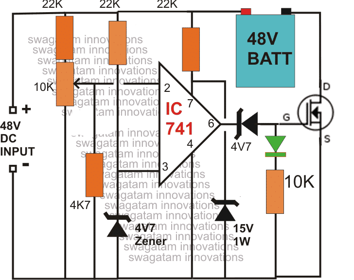
2) Current Controlled Version of the above Design
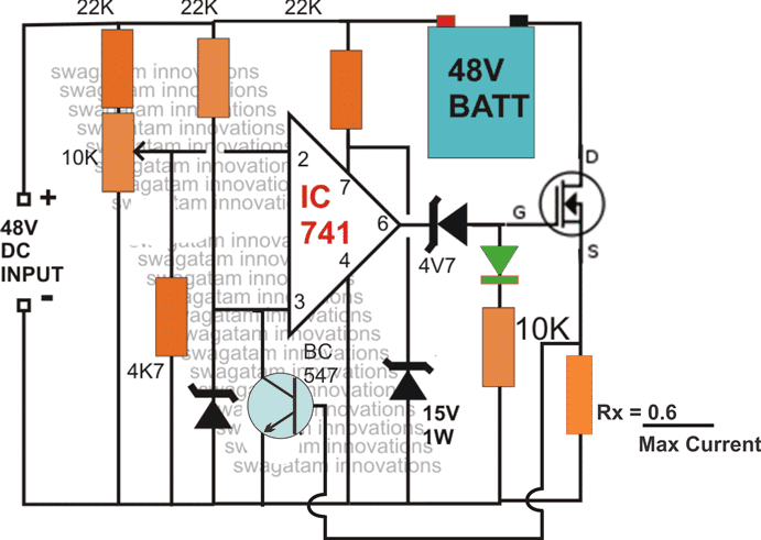
NOTE: The above diagrams mistakenly shows 48V as the input, the correct value is 56V. Because the full charge level of a 48 V battery is around 56/57 V.
NOTE: You will have to connect the battery first and then switch ON the input supply, otherwise the mosfet will fail to initiate for the charging process. Make sure the green LED remains illuminated after power switch ON, this will confirm the charging status of the battery.
The above design can be also built using a TIP142 and a red led charging indicator.
Simple 48 V 100 Ah charger Circuit using OP Amp and TIP142
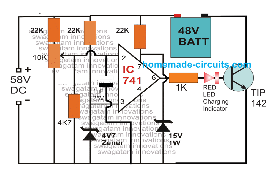
3) Making a Fully Automatic Version
The above circuit can be upgraded into an over charge cut off, as well as low charge restoring battery charger system, for charging 48V batteries.
The modifications enables the circuit to switch OFF the battery charging process at the set over charge threshold and restore back the process when the battery voltage falls below the low threshold value.
The 10k preset must be adjusted to set the full charge level while the 22k preset for detecting the lower threshold of the battery.
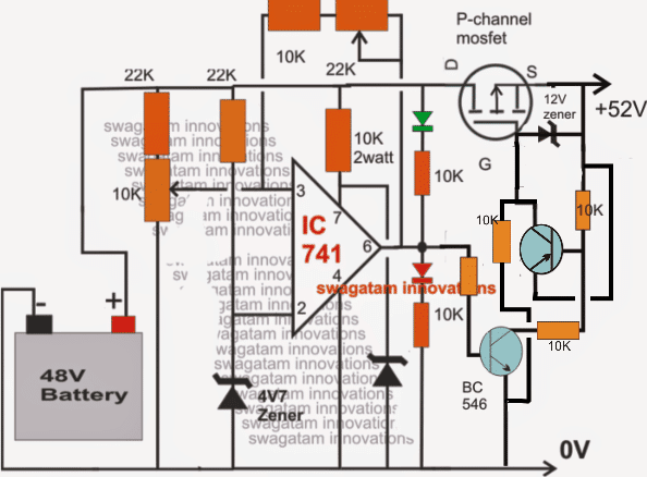
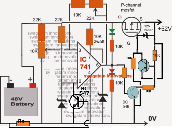
NOTE: In the above two circuits, please connect the RED LED in series with the BC546 base. This will prevent the op amp offset voltage from reaching the BC546 base and false triggering.
Simplifying the Design
The above design can be further simplified as shown in the following image. Notice that the input pins of the op amp are swapped in this design, which allowed the elimination of the extra PNP BJT from the circuit.
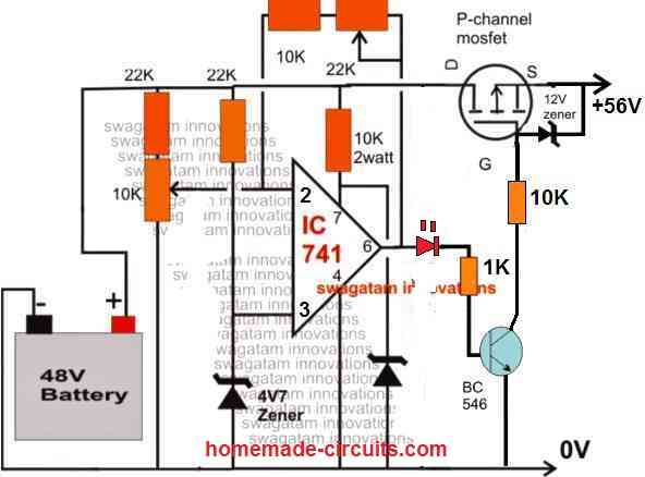
The above circuit can be also built using PNP BJT instead of a MOSFET, as shown below:
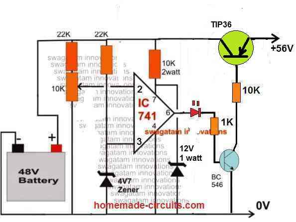
You can also add an current control feature to the above circuit, as shown in the following diagram:
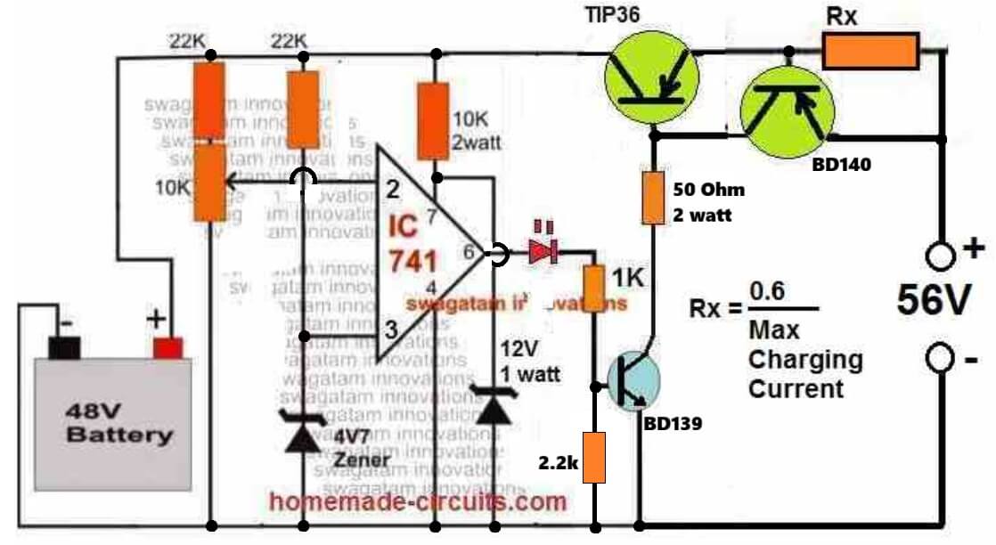
Complete Parts List
- Resistors are all 1/4 watt 5% CFR, unless specified
- 22k = 2
- 10k preset = 1
- 1k = 1
- 50 Ohm 2 watt = 1
- Rx = As per the formula
- TIP36 Base Resistor = (Input Voltage - 0.7) * hFE / Max Charging Current
- Semiconductors
- Zener diode 4.7V, 1/2 watt = 1
- Zener diode 12V, 1 watt = 1
- BJT TIP36 + BD140 = 1 each
- BJT BD139 = 1
- LED RED 5mm, 20 ma = 1
- IC 741 = 1
- Heatsink for TIP36 = 1
How to Set up the above Circuit:
For setting up procedure, the sample power supply should be connected across the points where the battery is connected, the mosfet does not require any attention initially. DO NOT connect the battery while carrying out this procedure.
Also keep the 22k preset link disconnected initially.
Apply the higher threshold level across the above mentioned points and adjust the 10K preset such that the RED LED just switches ON. Seal the adjusted preset with some glue.
Now reconnect the 22k preset link back into position.
Next, reduce the sample voltage to the lower threshold value and adjust the 22k preset such that now the green LED just lights up, while switching OFF the RED LED.
If you find no response from the circuit try using a 100K preset instead of the 22k preset.
Seal the adjusted preset as above.
The setting up of the circuit is over and done.
Please note that during actual operations, the above circuit will remain functional only as long as a battery stays connected at the shown points, without a battery the circuit will not detect or respond.
Feedback from Mr. Rohit
I have a 50-52v solar panel setup which is charging a 48v 78ah battery. What I want is when my battery is fully charged that is it reaches to 54v the battery charging stops and the supply which is coming from the solar panels is directed to another port from which we can charge any other device connected to the port. This charging should only continue till the battery is above 48v. Once it reaches 48v the battery again starts charging on solar panels and the supply to the other port is stopped.
Hoping you will reply soon.
My Response to the above Circuit Request
You can try the last circuit from the following artcilehttps://www.homemade-circuits.
Regards




Questions & Answers
check the current and voltage rating of the mosfet in its datasheet, if it's more than 60V and 20amps, then you can use it.
Sir … How can I used it to charge 24v battery … And what I change in the circuit
How can I charge 24v battery
you can use the last circuit as is shown, or alternatively try this one:
https://www.homemade-circuits.com/2012/02/how-to-build-automatic-6-volt-12-volt.html
Hi Swagatam, may I know how is the charging current being controlled in this circuit?
Hi Chamcl,
the above circuit does not have a current control feature, it can be added though.
So I'm actually going to need an Op-Amp and implement something like a voltage follower to have current control? Thanks in advance
48v,20ah(4 nos,12v*20ah battery series total volt 48v full charge 52v) escooter charger 48v 3a charger) and gate volt how much?
48v,20ah(4 nos,12v*20ah battery series total volt 48v full charge 52v) escooter charger 48v 3a charger) and gate volt how much?
dear sir,
please modify the 3rd circuit in led resister value and ic pin 6 to mosfet gate resister value and 22k preset value
Dear Subramanyam,
led resistor value is OK.
pin6 voltage will be equal to the zener voltage at pin7 of the IC…use a 15v zener here.
It's a lengthy and confusing procedure, better to check it practically by attaching a 1k resistor across it's gate and positive, and confirming a lamp activation across its drain and ground by touching its gate to ground.
Hi mate thought id ask to see if you could help me atvall as no one else seems to be able to, I need to charge 4x12v 75ah lead acid batteries from a 12v input. This is going to go into my van so will be charging from van alternator, looked at the alternator and it says 120a is there anything you could suggest and is that possible. It would need to cut out when it had fully charged the batteries and could do with being quite a good amp setup to charge that bit quicker than say a 3a system. Thank you in advance
Not sure I will get notifications through this butbif not my email address is babyboyk@aol.com
according to me, you will have to make the circuit that's given at the bottom of this article:
https://www.homemade-circuits.com/2012/05/make-this-voltage-stabilizer-circuit.html
you will need 4 of these with a common input….the individual 4 outputs will connect with the positives of the 4 batts.
all the negatives should be made into a common rail and connected with the alternator negative.
however the above set up would not give you an automatic cut, for that you will have to modify each individual circuit with additional parts as done in the following design:
https://www.homemade-circuits.com/2012/02/how-to-build-automatic-6-volt-12-volt.html
Wow lol way to complicated for me the thing is if you look at how 4x12v batteries are wired up to get 48v if you joined something up to all the positive wires then used the earth surely at some point on the batteries you would be running positive strait to negative somewhere along the battery cables. Ive done a drawing of it and dont think it would work, the only other thing I could do is add another alternator to the engine wich is possible and have it rewound to give out 48v and isolate the earth and just go strait to the batteries, someone said a car alternator is actualy 3 phase and generates 110v its the regulator and rectifier that trims it down so isnt there a way to change the regulator myself to give out 48v and isolate the earth then some how work out what amps that would give me
My suggestions are lengthy but not complicated,moreover the idea is technically correct and extremely safe…it will take care of your batteries for years to come.
Your idea could be quick but hazardous and non-friendly to the batteries.
Modding an alternator?? do you think it would be an easy job? Even a slightest mistake could mean fire and explosions.
Charging batteries by connecting them in parallel without appropriate isolation is never recommended.
So how much in gbp would it cost if you could make something for me to save blowing myself up lol
shipment could be a big hassle…so may be not a feasible idea to get it done from India
lol you wont blow up anything believe me, i'll show you how to do it step wise.
could you please procure the IC LM196 or LM396 one for each battery in the meantime??
As soon as you get them we can proceed with the construction, of course i am assuming that you know all the basics such as soldering, resistor color codes, mounting parts on pcb etc.
Just a quick thought before I make myself sound stupid by saying I can solder but thats about it lol could I get a permanent magnet wind turbine generator the 48v version and boltbthat to the engine and run it through a wind turbine regulator I could be realy wrong but just thought the only diference is its my engine driving the motor rather than the wind. But no idea about wats amps snd volts calculations lol with me having 4x 12v 75 ah batteries what sort of wattage or amp or even voltage for it to work. Like I say just a thought lol i can repair most electronic or electrical things but dont realy understand the ohms law thing i like working on circuit boards but wouldnt know where to get a circuit board from like you have in your pics with nothing soldered onto it to start with. What I do have here dont know if it might be the same as what is on your pics, I hav 2x kemo m102n accumulator chargers these are ment to charge 2x 12v batteries up so I bought 2 of them a while ago thinking it would do the job but like I say when I looked at the wire diagram I would have ended up with a strait positive to negative short with the batteries still connected up.
Considering your limitations, I think the last design in the following article would be the best for your application:
https://www.homemade-circuits.com/2013/08/connecting-batteries-in-parallel.html
The lamps are 24V truck head lamp bulbs….as long as the lamps stay illuminated would mean the charging of those particular bats are in progress,once the glow fades off would indicate a fully charged battery.
The arrangement is the safes according to me without much electronics.
Hi Swagatam, Ami battery byke charger toiri korchi, 12volt 20amp battery ache 4te. total voltage 48. ami ei page er 1st diagram ta toiri korbo thik korechi, etay to Hi voltage cut off ache, kintu 12 volt er battery te full charge hole 14.2 volt hoy, se karon e mot voltage hobe 56.8 volt ba pray 57 volt, ei circuit daigram e sei voltage e cut off kor jabe to ? ar ei prothom diagram tate ami ki mosfet use korbo seta ektu janao. tomar ei blog amader moto electronics premi manusher onek upokar e lagche. onek dhanyobad tomay, ei blog din e dine aro onek somriddhyo hok ei asha rakhi. – Dhrubajyoti
Hi Drubajyoti, thanks very much!
yes you can use the first diagram in the above article, and use a supply of 56V approximately as the input.
Without connecting the battery adjust the preset such that the LED just shuts off at 56V input.
After this switch OFF power, connect the discharged battery and then switch ON power again for the required charging until the supply cuts off automatically.
You can use a transistor TIP122 in place of the mosfet, use a large heatsink for it.
The input current should be 1/10th of the battery AH, that is around 20/10 = 2amps
Swagatam, tomake onek dhanyodab eto sojoj kore bujhie debar jonyo..Amar kache MJE 13007 transistor ache, ami ki TIP122 er bodole seta lagate pari ?
sorry Dhruba, MJE13007 will not work properly, you will have to use a TIP122 only.
Hi Swagatam, I simulated circuits 2 and circuits 3 with TINA and I found out that the currents flowed through the battery were both more than 30A. The cause of these were found to be the very high gate source voltage across the p-mostfet (i simulated with IRFP9140). can you comment on this?
thanks
Cham
Hi Cham,
You are right, we need to add 12V zener diodes across the gates of the shown p-channel mosfets for correct operations.
Thanks.
the 12V zener is to be connected between the gate and the drain of pMOS? what is the role of the OpAmp in this case? it doesnt seem to be helping in ensuring constant current does it?
the opamp cuts off the mosfet gate voltage when the battery is fully charged by applying a high logic at pin#6. this happens as per the setting of the preset a its pin3
the opamp is for controlling over charge of the battery, not the current.
Dear Sir
I have al-ready request the plz send to me 12vx4(48v ) Circuit when the battery discharge the battery bank to get 46v around . relay cut off with circuit diagram and install the parts in detail plz sir……
Dear Kailash,
Try the second circuit in the above article.
replace the mosfet with BC546 transistor. Connect its emitter to negative line of the circuit and connect a relay across its collector and positive, relay should be 48V rated.
Pleas I need a circuit that can charge 12v 100Ah battery for 2kva inverter
automatic or ordinary, pls specify.
Hello Mr. Swagatam;
how about battery over discharge cut-off curcuit for 48V battery. assume that, when battery level reduced to 43V, curcuit should cut-off the load, and when battery level reach to 46V curcuit should supply the load. do you think it is possible to make using op-amp 741 such a circuit? i think it is easy when battery level at 43V cut-off is easy, but re-conducting at 46V will be difficult?
Could you pls advise?
Hello John, yes it's possible, the above circuits are all designed to cut off and switch ON at the any desired high and low thresholds within the reange, so it's already there in the above shown design
Hello Swagatam;
i build third circuit, when i aplly the 52VDC, as per the cicuit set up procedure, while playing 10K preset, red led supposed to lit or off but strangely from the moment apllyinng 52VDC greed led lit, and do not switched off what ever i try and red led do not light at all. so actually i could not setup circuit.
Could you kindly tell what is the procedure to setup. pls note that, i follow your circuit set up procedure, with some trial and error also i could not fix. here below your comment which i have tried as well.
don't bother about the LEDs remove them for the time being or use 10K resistors.
Just check the output voltage while adjusting the preset. Do it in the following manner:
Initially keep the 22K feedback preset link disconnected.
feed approximately 52V DC to the circuit, with some trial and error adjust the 10K preset to make the output (where the battery would be connected) switch OFF. Flip the preset to and fro to confirm the adjustment….now glue the preset tight.
Now reconnect the 22k preset link back into position.
next apply a 46V DC input and adjust the 22k preset to restore back power at the output, if it gives problems increase the preset value to 100K.
the circuit is all set now
What im trying to set up is; at 43VDC battery should dissconnect the load and when battery level reach 46VDC or 47VDC battery should re-connect to load. is it possible with third circuit above?
you kind response will be highly appreciated.
regards
john
Hello John,
It will definitely work if you do as per the abve stated instructions.
It has to work.
The idea is (with a 46/47V input) to make the pin3 voltage of the IC just higher than the pin2 voltage of the IC by tweaking the pin3 preset so that the output of the IC is forced to go high (RED LED ON), until this happens meaning as long as pin2 V is higher than pin3 V, the output stays low (green LED ON)
You'll have to implement this by connecting the sample power supply input at the battery end….not at the mosfet end.
You can check the proceedings as explained above with a multimeter.
And as mentioned in the earlier explanation the feedback link should disconnected while setting the 46V threshold and must be reconnected and brought to use while
setting up the lower threshold cut off
Hi Swagatam;
İm a new bee in electronics,thx for the response, here below what i have seen, when, i try to build third circuit.
1-)Since im observing battery discharge cut off side, i have feed 52Vdc sample voltage to battery end,(not mossfet side) .
2-) i saw green LED lighted but not the red LED(red led never lighted actually,green led always lighted).
3-)İ checked with the help of multimeter voltage at PIN number2 of IC and saw 3,6V
4-)İ checked PIN number 3 of IC and voltage was 3,1. with the 10K preset i increase the level 3,8V.
5-)İ checked voltage at the output of PIN number 6 , 2V low logic.
6-) İ inserted 22K preset and feed the sample voltage 43V, nothing change, then i change to 22k to 100K preset, output of the İC became 14V, high logic.
7-)i remove the sample voltage source and connected the actual 48V battery and connect the load at mossfet side, battery level reduced to 43V but mossfet did not cut off the load.
😎 gate voltage for mosfet is maximum 14V when İC is high logic level and 2V when IC is low logic. but mossfet drain and source voltage is 42V. mossfet did not cut out out the load.
do you think, did i do correct? if i did correct, then when battery level falls to at 43V i should have seen the load cut out from the battery suplly.
Could you advise pls.
regards
Hi John,
Yes your procedures look OK, I think the IC could be duplicate or faulty.
I would recommend you to make the following basic set up as shown in the first circuit from this link:
https://www.homemade-circuits.com/2011/12/how-to-make-simple-low-battery-voltage.html
Use 12V, and check if the LED toggles ON/OFF at a particular point on the preset. If it doesn't work with your IC you can be sure the IC to be faulty.
You could try swapping the input pins of the IC for a reverse effect from the same.
Hello Swagatam;
your site is really informative, thanks for the response.
i have established the curcuit, without the mosfet part, operating just fine, i manage the trip at 45V and re-trip the 48V. but mosfet do not trip the load.
Since by placing 15V zener at opam supply,you fix the output of the opam at 14,6V(High logic case), gate of the mosfet is receiving 14,6v at 48,49,50,51,52,53,54V supply voltage. At 45V sample voltage mosfett gate is receving 2.2V(Low logic) but mosfett do not make any cut out for the load. pls note that at 45V sample voltage, drain and source of the mosfett is 45V. gate is only 2.2V. how will mosfett will trip, when gate is receiving only 2,2V in low logic case and 14,6V at high logic case,in the other hand drain and source receiving 45V. i have try N-channel and P-channel both.
Could you pls advise for the mosfett part.
Thank you John,
In order to block the 2.2V and make it zero you can try adding a 3V zener in series with the gate of the mosfet. (anode to gate)
Alternatively you could quit using fets and try BJT such as TIP142 for making things much easier.
In any case the 3.3V zener would be required at the output of the IC.
This should hopefully solve the problem.
Hi Swagatam;
İf, i remove the opamp suply voltage component(PIN number7) what i mean is, removing 15V zener and 10K resistor, by this way output of the opamp voltage will be the same suplly voltage available in the battery.
right now, output of the opamp is limited to zener voltage, which is max 14,6V(in high logic case). do you think, ill put the circuit in danger? by removing zener and 10K resistor at PIN number 7. the circuit can also operate without zener and 10K resistor at PIN number 7 ?
regards
Hi John, I would have never put the zener at the IC supply if it could tolerate anything above 40 volts.
The IC and the mosfet would get instantly damaged if the protection zener was removed.
Moreover any mosfet would nicely work at around 12V, irrespective of their S/D specifications, so 14V is quite optimal, I thought you were worried about the leaking 2.2V which was not allowing the fet to switch OFF at full charge levels.
Hi Swagatam;
i was bussy, just today had some time to experiment on circuit, evetually failed to switch off mosfet.
Actually; i was worried both the case, about 2.2V during low logic of the curcuit and not switching off the mosfet(you said that drain and source voltage doesnt matter and PİN7 have nothing to do), as per your suggestion 3.3 zener solved the 2.2V problem, i mean low logic,i get 0v instead 2,2v. but mosfet, from the moment, curcuit is energized, become on, and never becoming off. it is very strange.
i gave up on mosfet, i dont know, why, it is not becoming off, damn thing, always on, regardless of the low logic or high logic condition.
Could you advise me about BJT, i shall connect base to zener 3.3 (PİN6), collector to positive supply and emiter to load, right? and how many pcs would be enough? no need to make some darlington pair etc right? simple 1 transistor instead of mosfet right?
Hi John,
I think we are missing something here….the circuit uses a p-channel mosfet which will switch OFF with a positive that must be at least 5V more than its source voltage.
It means we need to supply at least 5 + 48 = 53V in order to switch OFF this mosfet.
oh that's a big blunder!!
The BJT will also face the same issues, it will require at least 48 + 1 = 49V in order to switch OFF completely.
And our opamo is helpless, it's not able to supply anything above 12V.
So that's the problem we are facing presently.
I would rather suggest that we switch to a N-channel device instead of the P-channel.
All connections remain as is.
we just need to put the N-channel in series with the negative supply instead of the positive, and swap the input pins of the op amp with one another.
Hi John, I have corrected the diagrams with respect to the above discussion, please check them out.
…by the way the p mosfet would require just 48V in order to switch OFF in your case and not 48 + 5 as wrongly mentioned in my previous comment:)
John, I was just going through your first comment and it made me realize that perhaps the last circuit will need to be modified differently for your application.
The above circuits are all configured for charging the battery and not for connecting or disconnecting a load with the mosfet.
So I am a little confused here with your following statement:
"What im trying to set up is; at 43VDC battery should dissconnect the load and when battery level reach 46VDC or 47VDC battery should re-connect to load. is it possible with third circuit above?:"
I would like to have a little more clarification on this.
Hi Swagatam;
regarding to your question, İ have managed to cut off at 43V and re-connect at 47V, if i be more spesific.
1-)i constructed to curcuit except mosfet part, and sample voltage suplied, where battery is printed. i aplly sample voltage 48V(where battery printed), i check PİN number2, it was 3.6V due to zener reference voltage. PIN number3, i adjusted to 3.7V(By the help of 10K pot). then i connect to hysteresis link 100K and reduced to sample voltage 43V . i played with 100K pot till, where output of the OPAMP just switch to low logic.
2-) then i experimented the curcuit at 43V, it was cutting output of the OPAMP, to low logic and at 47V, it was again reconnecting(making high logic output). then i replaced the PİN2 to PİN3 to see output of the opamp at 43V high logic and at 47V low logic. comparator part working superbly.there is no problem at all.
3-) my trouble strated, when i try to switch OFF and ON the mossfet, first, i thought due to P-channel N-channel mosfet diffrence, but later, i realize that, its always ON regardless of the OPAMP condition(Low logic or High logic no difference,always ON due to same supply line of the source, meaning at 43V supply voltage, gate of the mossfet low logic, but Source of the mosfet 43V and drain also 43V and mosfett ON, at 47V gate is high logic 12V at the gate, source 47V and drain 47V,what ever the supply voltage mosfett is ON), when i try to increase output of the OPAMP to full suplly voltage,by this way gate would also receive full voltage (cancelling PİN7 limitation) then mosfett started to act but not perfomed well as well.in order not danger curcuit, i asked you, you said, dont do it(but i did not check thoroughly increasing the output of the OPAMP, you said bad idea).
my question is, can i do, with this circuit 48V battery disconnect? ill constructed battery, where battery is printed and where you placed to 52V DC input, ill construct to load, and switch ON and OFF the load, by the help of this curcuit? if i manage to OFF and ON the mosfett then load also would be ON and OFF at desired level of battery since comparator part is working superbly.
Could you advise pls?
Thanks John, It's great to hear that you have succeeded in making the circuit work as per the explanation.
You are right, the second circuit can be used for connecting or disconnecting a particular load in response to the set battery thresholds, it could be a battery or any other load whatsoever.
You may go ahead and make the second design for the intended operations, in fact you could even try the first circuit for the same, using an N channel would make the design much easier to configure as could be witnessed by comparing the above schematics.