In the following post I have explained a simple low battery indicator circuit by using just two inexpensive NPN transistors. The main feature of this circuit is its very low stand by current consumption.
The Circuit Concept
We have so far seen how to make a low battery indicator circuits using a 741 IC and a 555 IC, which are no doubt outstanding with their abilities of detecting and indicating low battery voltage thresholds.
However the following post relates yet another similar circuit which is much cheaper and employs just a couple of NPN transistors for producing the required low battery indications.
You may also this Low Battery Alarm Circuit
Advantage of Transistor over IC
The main advantage of the proposed two transistor low battery indicator circuit is its very low current consumption compared to the IC counterparts which consume relatively higher currents.
A IC 555 would consume around 5mA, a IC741 around 3 mA, while the present circuit would just consume around 1.5mA current.
Thus the present circuit becomes more efficient especially in cases where stand by current consumption tend to become an issue, example suppose in units which depend on low current battery supplies such as a 9V PP3 battery.
Circuit can Operate at 1.5V
Another advantage of this circuit is it's ability to work even at voltages around 1.5V which gives it a clear edge over the IC based circuits.
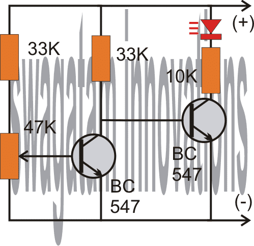
As shown in the following circuit diagram, the two transistors are configured as voltage sensor and inverter.
The first transistor on the left senses the threshold voltage level as per the setting of the 47K preset. As long as this transistor conducts, the second transistor on the right is held switched OFF, which also keeps the LED switched OFF.
As soon as the battery voltage falls below the set threshold level, the left transistor is no longer able to conduct.
This situation instantly switches ON the right hand side transistor, enabling the LED to illuminate.
The LED switches ON and provides the required indications of a low battery warning.
Circuit Diagram
Audio/Video Explanation:
The above circuit was successfully built and installed by Mr. Allan in his paranormal depletion detector unit. The following video presents the implementation results:
Upgrading the above Transistorized Low Battery circuit into a Low Battery Cut-off Circuit
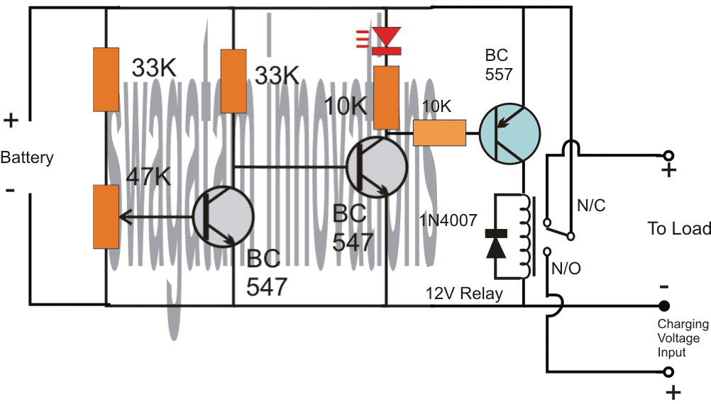
Referring to the above diagram, the low battery indicator is formed by the two NPN transistors, while the additional BC557 and the relay are used for cutting OFF the battery from the load when it reaches the lower threshold, in this state the relay connects the battery to the available charging input.
However when the battery is in its normal state the relay connects the battery with the load and allows the load to operate through battery power.
Adding Hysteresis
One drawback of the above design could be the chattering of the relay at the threshold voltage levels, due to the battery voltage dropping immediately during the relay changeover process.
This can be prevented by adding a 100uF at the base of the middle BC547.
However, this still wouldn't stop the relay from constantly switching ON/OFF at the low battery changeover threshold.
In order to rectify this, a hysteresis effect will need to be introduced which can be accomplished through a feedback resistor between the collector of the BC557 and the middle BC547 transistor.
The modified design for implementing the above condition can be seen in the following diagram:
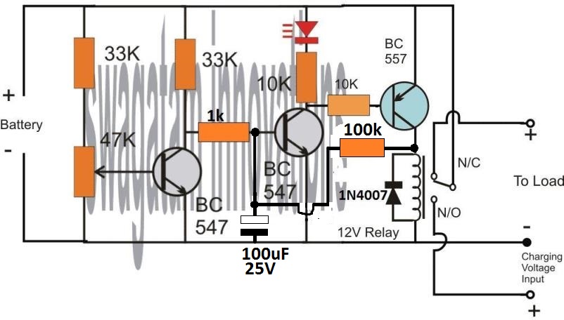
The two resistors, one at the base of BC547 and the other at the collector of BC557 decide the other threshold of the relay changeover, meaning the full charge cut off threshold of the battery.
Here, the values are arbitrarily selected, for accurate results these values will need to be optimized with some trial and error.
Low Battery Indicator using a PUT
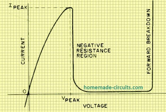
This low battery indicator circuit is used with a programmable unijunction transistor (PUT), since the threshold characteristics of the UJT could be effectively defined, and can be designed to flash a connected LED indicator.
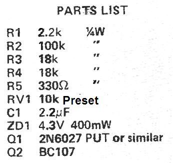
The PUT (Q1) is configured like a relaxation oscillator circuit.
As the supply voltage which is being monitored (Vmon) starts dropping, the gate voltage of the PUT (Vg) also begins dropping, while its anode voltage (Va) basically stays constant.
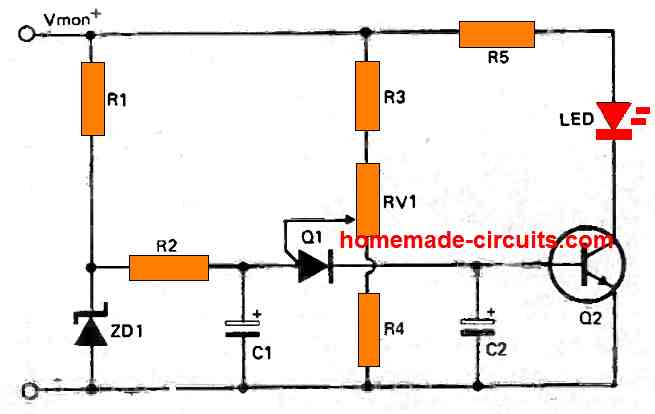
The PUT begins oscillating only as soon as the gate voltage drops below Va by 0.6 volts. As Vmon comes down further, Vg also drops accordingly and this situation triggers ON the PUT.
Therefore, the period of the cycle becomes lesser and this causes an increase in the frequency of flashing indicating that the battery has become too low and needs to be changed.
Parts List
Car Low Battery Monitor Circuit using a Single BJT
Here's a straightforward car battery monitor that eliminates the need for constant meter watching.
When your battery terminal voltage reaches a reasonable level, such as 12.5 volts as measured by a digital multimeter (DMM) or a reliable meter, you can adjust resistor R1 until the LED illuminates.
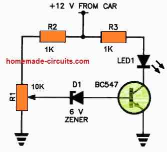
If the battery voltage drops below this threshold, the zener diode will switch to a non-conductive state, cutting off the base current to the transistor.
As a result, there will be no collector current, causing the LED to turn off.
If you don't notice the small indicator light shining on your dashboard, it could indicate a low battery condition!
It's advisable to use a green LED for better visibility. For R1, it's recommended to use a 10-turn trimpot for precise adjustments.



Questions & Answers
hello sir can i use this circuit for 12v battery?
yes it can be used with 12V supply also.
hi sir,
i am not good in electronics please guide me how second transistor is off while the voltage level is high. And how second transistor is on while low voltage. thanks
At higher voltages the left transistor conducts and grounds the base of the right transistor so that it gets switched OFF, at low voltages the left transistor doesn't get enough voltage at its base to conduct and switches OFF itself which initiates and switches On the right transistor.
This circuit is going on my little single cell micro helicopter to light a super bright led when battery goes from 4.20volts down to 4.0 v. Currently I'm shrinking it down & taking it off the breadboard.
Wow! that's great….go on
The transistor orientation will be exactly as given in the above diagram, just the supply will need to be reversed, and also the LED polarity.
That's correct!
47K is a preset to be precise,
yes you got it right about the 33k resistors, anyway nothing is crucial here.
hai sir, i want to use this circuit with 12V 4.5Ah battery but i dnt have 47k preset but am having 10K preset.. what to do now ??
10K preset will also work, you can use it.
Dear John,
Thanks!
To make it work as an over charge indicator you will need to alter the polarity of the transistors.
You will need to replace the transistors with BC557.
Its orientation will be exactly as given in the above diagram, just the supply will need to be reversed, and also the LED polarity.
However it won't give a sudden glow, a dim glow could be witnessed when the level is within 0.5V near the set threshold.
I meant that the LED won't produce sharp turn ONs rather grow brighter slowly as the threshold is reached, but at the actual threshold the brightness would be optimal.
Probably not possible through this simple design, you will have use an opamp circuit for that, as shown here:
https://www.homemade-circuits.com/2011/12/how-to-make-simple-low-battery-voltage.html
Hi Swagatham,
Hats off to your contribution. I tried this circuit https://www.homemade-circuits.com/2011/12/how-to-make-efficient-led-emergency.html, the second one with LDR, through another transistor bd140. It works like a charm. Initially i had set up the ldr ckt without low bat indicator for 440ma. R1 220E and p1 10k. I know one more stage of pnp is required to connect low bat ckt to LDR ckt to cutoff the battery power to LEDs. But i dono what to be used and where to connect to maintain the same 440 ma as output to LEDs. Plz suggest the circuit to be used. Thanks. Sham.
Hi Sham,
thanks!
For adding a low voltage cut off in the circuit you can repeat another stage identical to the LDR stage, with the following changes.
Use a 10k preset instead of 100k, remove the LDR and use a series resistor equal to 10k for the ground link. Adjust the preset such that the LEds just shut off when the battery voltages reaches 5V
I tried connecting the circuit as per your suggestion, but i could not get the desired result. So changed the values as given. I connected one more bc557 in the same manner as ldr ckt. Emitter to vc+ via 1k pot and other end to base of 2nd trans. Again base to grnd via 1k resis. Collector connected to base of bd140. Now ckt switches off with 5v battery when preset is calibrated but when replaced with 6v battery it continues in the same off state unless i have to recalibrate to new setting. Actually it should be ON since the voltage is more.
When checked at 2nd trans collector during LED off state at 5v it was reading 3.4 volts. When 6 volts battery was connected, it was showing 4.4 volts which keeps the bd140 base at high and hence it was still off.
Plz suggest me what to do.
Ho… BTW addition to my previous reply, in ldr ckt, i hv used 10k pot instead of 100k at emitter and 470E for bd140 base and grnd. I hv connected ldr to grnd without 1k.
plz suggest where the 2nd bc557 collector to be connected?
Sham, please try the 4rth circuit as shown in this article:
https://www.homemade-circuits.com/2011/12/how-to-make-efficient-led-emergency.html
Sure Swagatham, will try this and give feedback.
Hi Swagatam,
I tried with 4th ckt. I am not getting Battery cutoff. When emitter is connector to base of bd140 indicator is not lighting up.
Hi Sham,
Remove the LED, connect the collector directly to positive and then check.
Yes Swagatham, tried that too before posting. Changed the resistor values to lower ones too.. 🙁
according to me it should have worked, anyway there's only way left now… revert the connections back to its actual form as shown in the above article.
Connect an additional BC557 transistor base via a 10k resistor to the collector arm of BC547 where the LED is present.
connect the emitter of BC557 to positive and collector to base of BD140.
adjust the 47k preset such that at 5V all the white leds just shut off
This is 100% work, otherwise the issue could be something else.
Hi Swagatham,
I tried the ckt you suggested. But no response. I did some rnd and found that the biasing of ldr ckt is taking over the 557 one.
When pos supply from transformer is applied to base of bd140, ckt switches off. That means pos supply from battery is not sufficient to turn off bd140. If i connect pos of transformer to 557 emitter, my requirement is not met, bcos in absence of power supply battery may get drained.
I know its straight forward solution. but its not happening. Hope to get better solution to this.
Hi Sham,
the suggested circuit is perfect, it's the ultimate way of doing it and should work.
When the low voltage LED lights up, check the voltage at the junction of collector of the BC557 transistor and base of BD140, it should be equal to the battery voltage.
check by keeping the meter prods across positive and base of BD140
with potential at base of BD140 equal to the battery voltage, there's no way it can conduct.
you may also try increasing the base/ground resistor of BD140 for better and instant response.
Good day sir!!! another question from your no. 1 fan!! :-)…
1.Do you remember the the Ultrasonic weapon circuit of yours? You mentioned about the power supply which is 12v to 18v. Can I use 2 x 6f22 9v battery which would become 18v? And in case yes, I will put the above circuit. What modification will I make so that the led will glow at 12v?
I will always credit you in my projects…
My teacher once asked me in one of my project like the transformer less emergency light, she said "who is this Swagatam Majumdar in your acknoledgement" I said "He is an Engineer from India."
Thanks very much Achiless I appreciate your enthusiasm!
9V PP3 battery will not work for too long, because the ultrasonic weapon circuit could consume considerable amount of power at a go…..therefore you will have to either go for mini SMF batt or arrange many 1.5V pencil cells in series…you would require 12 nos of them in series for optimum results.
sir can i use it for 12V supply? what changes do i need to do? thank you 🙂
yes you can use it for 12V also.
I made the above circuit it.s working marvelously now I need a battery full indicator circuit as simple as the above one.
Thanks!
To make it work as an over charge indicator you will need to alter the polarity of the transistors.
You will need to replace the transistors with BC557.
Its orientation will be exactly as given in the above diagram, just the supply will need to be reversed, and also the LED polarity.
Sir I would like to make a circuit which includes a laser light and laser detector where they both can face each other when any human body or any other object comes in between the laser light and detector it should give alarm. I don.t have good idea please help me in making the diagram and description of components needed.thank you..
Mujahid, you can try the first circuit shown the following link:
https://www.homemade-circuits.com/2012/03/how-to-make-simple-scr-application.html
replace the "sensor" points with an LDR
Sir Swagatam circuit you recommended are great. The problem is that I cannot use an Ldr in open surroundings where it can be affected by sun light and other lights as well. I need circuit where there is specific light and its detector so when any object interrupt them means coming between the receiver and detector it should give alarm. I can configure the remaining circuit with scr application circuit.
Mujahid, you can keep the LDR enclosed inside a pipe like enclosure and align the laser beam such that only this beam enters the pipe, no other light is able to enter.
as shown in the last diagram in this ink:
https://www.homemade-circuits.com/2013/02/make-these-simple-cheap-home-burglar.html
otherwise you will have to go for an IR proximity detector circuit as given here
https://www.homemade-circuits.com/2013/10/accurate-infrared-motion-detector-or.html
How would i make this work for a 36v battery with an alarm at 30v please?
you can use the same circuit for 36V also, simply adjust the preset for 30v LED illumination
Dear sir You mentioned about the ic 4017 that it produces sequential output what does it mean kindly explain a bit.thank you.
Dear Mujahid,
please read this article for more details:
https://www.homemade-circuits.com/2011/12/how-to-understand-ic-4017-pin-outs.html
Ic 4017 is great but you are greater than it hence you made it easier for us to understand.thank you
You are welcome!
can i use a different resistor than a 33k one??
yes any nearby value will do +/- 20%
Can i use a 68k one?
yes will do.
Can u please send the design of the above circuit.
can u please send me the design of the above circuit
Will this ckt work for 1.5 volt battery ?
To indicate its low voltage?
Plz give proper details of ckt if not?
yes it can be used for 1.5V also….reduce the 33k resistors to 1k that's all.