The proposed long range transmitter circuit really is very steady, harmonic free design which you can use with standard fm frequencies between 88 and 108 MHz.
Technical Specifications of the Transmitter
This will likely encompass 5km spectrum (long range). It includes an extremely consistent oscillator for the reason that you employ LM7809 stabilizer that is a 9V stabilized power source for T1 transistor and for frequency realignment that may be reached by means of the 10K linear potentiometer.
The output strength of this long range rf transmitter is approximately 1W however may be more significant should you use transistors like KT920A, BLY8, 2SC1970, 2SC1971…
Transistor T1 is employed as an oscillator stage to present a small power steady frequency. To fine-tune the freq. apply the 10k linear potentiometer this way: should you moderate, in the direction of ground, the freq. would probably decrease but when you fine-tune it in direction of + it would climb.
Essentially the potentiometer is needed just as a flexible power source for the a pair of BB139 varicap diodes.
Both of these diodes function as a changeable capacitor whilst you regulate the pot. By tweaking the diode capacitance the L1 + diodes circuit renders a resonance circuit for T1.
Feel free to employ transistors similar to BF199, BF214 however be careful not to use BCs. At this point you don’t receive yet the long range fm wireless transmitter due to the fact that the electric power is fairly reduced, a maximum of 0.5 mW.
How it Works
The proposed transmitter circuit works in the following manner:
Always encase the oscillator stage in a metal guard to avoid parasite frequencies destabilizing the oscillating stage.
Transistors T2 and T3 functions as a buffer stage, T2 as a voltage amplifier and T3 as a current amp.
This buffer stage is vital for freq stabilization simply because is a tampon circuit between the oscillator and the preamp and final amplifier. It happens to be renowned that bad transmitter layouts normally change freq. whenever you alter the finalized stage.
Using this T2, T3 stage this won’t occur again!
T4 is a preamplifier stage and is employed as a voltage power rf amplifier which enables it to produce adequate power to the ending T5 transistor stage.
As is demonstrated T4 carries a capacitor trimmer in its collector, this is definitely accustomed to render a resonance circuit designed to drive T4 to promote more advantageous situations and do away with those undesirable harmonics.
L2 and L3 coils has to be at 90 degrees perspective one to another, this is to prevent frequency and parasite coupling.
The concluding stage of the long range rf transmitter is equipped with any rf power transistor containing no less than one watt production power.
Utilize transistors like 2N3866, 2N3553, KT920A, 2N3375, 2SC1970 or 2SC1971 should you wish to produce a professional fm transmitter with ample power to take care of an extended spectrum zone. Should you use 2N2219 you will definitely get a maximum of 400mW.
Make use of an effective heatsink for the T5 transistor because it becomes slightly warm. Make use of a reliable 12V/1Amp balanced supply of power.
How to Set-up the Transmitter
Begin by building the oscillator stage, solder a tiny wire to T1 10pF capacitor out and hearing a fm radio, tweak the 10k pot until it is possible to “hear” a blank disturbances or maybe if you connect an music base you could listen to the melodies.
With a 70cm cord it is possible to take care of a 2 – 3 meter region simply with the oscillator stage.
Next carry on and construct the remaining of the rf transmitter, utilize correct shielding as suggested in the above explanation.
As soon as you have completed the transmitter design, hook up the antenna or more effectively a 50 or 75 Ω resistive load and make use of this as a rf probe, feel free to use 1N4148 diode in place of the probe diode.
Fine-tune yet again the 10k pot to favored freq. thereafter go to T4 stage and scale down the initial collector trimmer for highest voltage signal on the multimeter.
After that carry on with the subsequent trimmer and so forth. After that get back on the very first trimmer and readjust yet again until you receive the maximum voltage on the multimeter.
For one watt rf power you could possibly ascertain a twelve to sixteen Voltage. The method is P (in watt) is equivalent to U2 / Z, wherein Z is 150 for 75Ω resistor or 100 for 50Ω resistor, nevertheless one should keep in mind that the proper rf power is lesser.
After those modification, in case things are heading nicely hook up the antenna, keep on employing the rf probe, readjust once more all of the the trimmers right from T3.
Guarantee you don’t have harmonics, verify the TV and radio set to determine if there exists fluctuations on the band. Verify this in an alternative area, a long way away from the fm transmitter or antenna.
The unit is all set up to be used for exchanging music, talks, chats across the suggested range and bands.
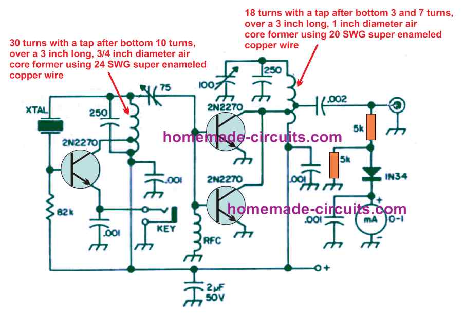
Circuit Diagram
All Inductors are air cored
L1 = 5 wounds / 23 SWG / 4mm silvered copper
L2 = 6 wounds / 21 SWG / 6mm enamelled copper
L3 = 3 wounds / 19 SWG / 7mm silvered copper
L4 = 6 wounds / 19 SWG / 6mm enamelled copper
L5 = 4 wounds / 19 SWG / 7mm silvered copper
T1 = T2 = T3 = T4 = BF199
T5 = 2N3866 for 1Watt / 2SC1971, BLY81,or 2N3553 for 1.5 to 2W power.
Feedback from Mr. Himzo (a dedicated follower of this website)
Hello Swagatam,
I have few questions about your long range fm transmitter.
Firstly about the shielding, what is the most simplest solution to avoid those "parasite frequencies"?
Secondly, what means those 1nF capacitors at the top? Can they be simple in parallel connection or they need to be separated to every transistor like in scheme?
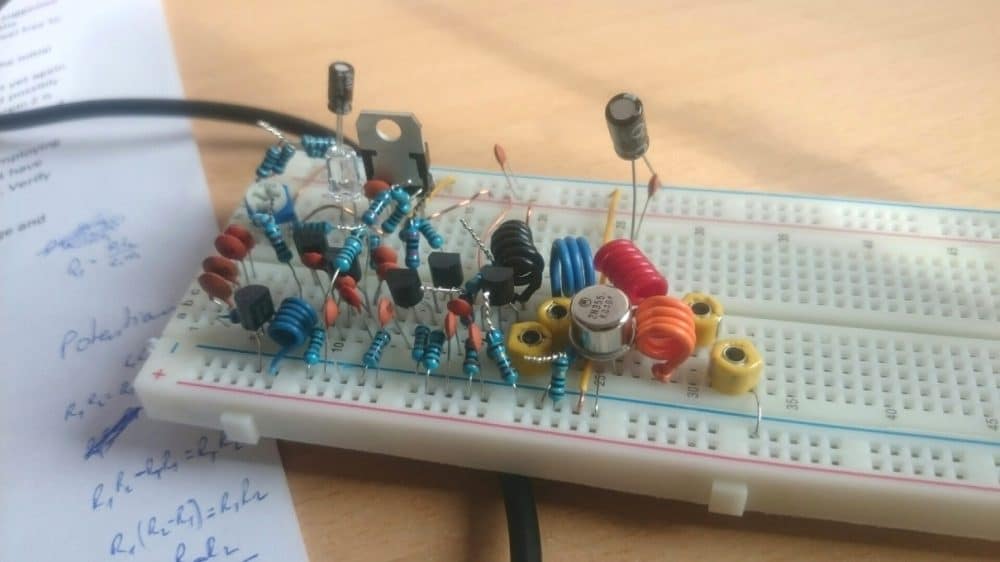
Thirdly, I sent you a photo of transmitter, I didn't turn on amplifier part because my heatsink is coming. Where can I put antenna for testing without amplifier (T5 stage)?
And lastly, how can I modulate those trimmers if I dont have plastic screwdrivers?
Thank you very very much, this is great project.
Your fan, Himzo.
Solving the Circuit Problem
Hello Himzo,
the simplest and the only way to shield the various sensitive stages is by using metal walls between the stages...
the 1nF capacitors should be positioned exactly where these are indicated in the diagram.... the picture which you have shown will never work... transmitter circuits require extreme care as far as their construction and positioning of the components are concerned.
You can never build a long range transmitter successfully on a breadboard, you will have to do it on a well designed PCB which should have a grounded track base layout encompassing all the thinner tracks, only then you can expect the transmitter to work...that too after careful optimization of the trimmers and by employing a compatible antenna.
Questions & Answers
Fine-tune yet again the 10k pot to favored freq. thereafter go to T4 stage and scale down the initial collector trimmer for highest voltage signal on the multimeter.
For this paragraph where do I put the multimeter probes to measure voltage?
Test the voltage across L4.
Hi,
Is it possible to be able to send bluetooth signal from a device via radio signal to a Phone/Tablet approximately 1500 meters. I have a project in mind but I’m struggling to find a solution
Hi, It seems it is possible, however I do not have the exact circuit diagram that would modulate RF with Bluetooth.
Hi , would you have any idea where I might start to look for one/
Thanks
Sorry, currently I have no idea about it!
Dear Mr. Swagatam, I am Krishna kumar from TVM, Kerala, an electronic enthusiast, looking for a long-range (5 km) RF (433Mhz) transmitter and receiver for my project to switch on and off an AC Power Source. If you have such a transceiver, please send me the details. Thanks in Advance.
Hi Krishna Kumar, sorry, I don’t seem to have this circuit with me right now, If I happen to find one will surely let you know…
i have managed and succesed to make all type of radio transmitter,,from 100m to 10 km but my question is how can I improve the range to 20km kindly assist me my email is peterkamau1344@gmail.com for replying
use amplifier to out.
Since you could build transmitters upto 10km range, you seem to have more knowledge and experience than me in this field. I do not have sufficient expertise to solve your query.
can i use this for sending multi-channel segnals
You can send multichannel signals through the shown single input
Hi Swagatam, please what are the diameters of the inductors?
Hi Sam, they are already given in the article, 4mm, 6mm, 7mm….
Thanks a lot. Keep up the good work, you are really making positive changes in the electronic world for newbies. Very fast and reliable replies. I always look for projects from your pages. Thanks again.????
You are welcome Sam, Happy to help!
I have built the transmitter years ago but with my own modification to get the range I wanted.
Hello Mr. Swagatam
I am building this circuit for a school project. Is there any way You could have a quick look at the PCB i produced? And I don’t exactly know where to put my antenna after. Thanks for your work and have a nice day.
Best, Tim
Hello Mr.Tim,
This project is not a school project and will require a high degree of expertise in the Rf field to successfully build it. So please proceed with caution.
The antenna connector is shown at extreme right across the “output” points
Hi Swagatam.
Thanks for the work on this project.
Can we make this transmitter for 5 Watts by simply changing the transistor?
And if we can, what part number do you suggest?
Regards.
Thanks Imran, that may be possible since the circuit has a separate driver stage. You can search online for a high power RF transistor, you might get some clue
Good Morning sir.
Please sir, i want make a final year school project of ( VOICE TRANSMITTER AND RECEIVER) please can you help me with the Circuit??
Hi Engr Bashir, you can try the following concept
https://www.homemade-circuits.com/homemade-walkie-talkie-circuit/
sir i want to make a RF transreciver of range upto 3km. Which gives a accurate data of that range. how could i make this model.
Hi Aakash, here’s one circuit that you can try:
makingcircuits.com/blog/powerful-transceiver-circuit-using-ic-mc2833-mc3363/
please,
apart from cabling is there any other way one could send video and audio signal up to a mile,if it requires any form of coding,can it be actualise,lf yes please,circuit diagrams.
thanks
I don’t know about video but audio can be sent through a transmitter above 1 km through a simple circuit, but might require special optimization and a special antenna for efficient transmission.
Thanks Mr Swagtam
I hope you will find solution..i believe in you
Thank you very much for sharing your knowledge. i am interested in the RF section of your design. ie the relationship between T5, L4, L5 and the two trimmers. Can you please shade some light on what is going on in that section. the closes idea i have is the working of a colpitt oscillator. The combination of the inductor L5 and the two trimmer capacitor has left me in the dark. I think L4 is a radio frequency chock. what is the power at the base of T5? Thanks
Thanks Abdul, They basically act like an LC tank circuit which resonates with the frequency of T4 stage and concentrates it many folds so that it gets amplified enough for the long distance transmission. Yes L4 is the choke, and L5 is the tank coil
hi Swagatam ,
could you able share your email id , i required 8 kilometers range transmitter and receiver ckt to trip my load my ELECTRICITY BOARD SUPPLY GOES off when DG is running . Here the constraints we are unable to lay the interlocking cable so we are going for wire less , if any circuit is there kindly suggest i will develop the same
Hi Venkatesh,
I have a 27MHz long range circuit designed by elektor electronics, but it can be extremely difficult to make and test such circuits for any newcomer. I would suggest you to buy one instead. Or you can use a GSM based design such as this:
https://www.homemade-circuits.com/24-ghz-10-channel-remote-control-switch/
Hi sir 1) I would like to know whats the use of those variable capacitors here. I dont know how to use it
2) What is shielding. What is its use
3) Which component is 100/0.5w
4) 10uf capacitor is of how many volts
5) Why 2 dotted lines in circuit which is connected to ground
6) Why T5 is based on watts and what is the difference between 1w and 2w output
Kindly please reply to me at mevivrg01@gmail.com
Hi Melvin, here are the answers:
1)Those are called trimmers, it is for optimizing the frequency and power output from the transmitter to maximum.
2) Shielding refers to adding metal partitions between the various stages of the transmitter so that processed signals across these stages do not interfere with each other and reduce efficiency, the metal can be preferably copper so that it can be fixed with the PCB by soldering.
3)100/0.5W = 100 ohm 1/2 watt resistor
4) 10uF/25V
5) The shield partitions explained above must be aligned across these shown dotted lines such that they stand like walls on these dotted lines…the height of these copper shield plates could be 2 cm and thickness could be 1mm.
6) T5 handles the power stage of the transmitter, and their watt rating indicate how much power each of these variants can handle and produce at the output
Hi swag its me again Melvin. Thanks for your reply but I’m a little bit confused of that first answer. So how to use those trimmers.
Hi Melvin, please read the comments, I have answered it in one of the comment replies.
Thanks swag
I have recently build lots of low power fm transmitter all claiming about 1km range but at most I could get 500mts only. I am not able to tune the circuit meaning to say that the oscillator and the tank circuit are not at same frequency and because of that I am getting signal at many places on fm band ie harmonics . how to tune such transmitter pls help. like in this you have got 4 trimmer capacitor how to tune them? which one should I tune first.pls help
disconnect the last T5 stage which has the antenna, and optimize the two trimmers to get maximum silence (null point) in the FM radio positioned at about 10 meters away, once this is achieved connect the T5 back and repeat the process without an antenna at a greater distance away from the transmitter.
Hello again sir swagatam I have no idea what component that bb139
Jamil, that’s a varicap diode
https://en.wikipedia.org/wiki/Varicap
Sir its possible to put crystal oscillator in transmiteer and receiver.
I am not sure how to do it, if you know you can try
Hello sir, My name is pakpa. I want to know something that is there any possible way to convert rc remote control car's remote to fm transmitter. Kindly help me.
Hello Pakpa, yes that may be possible by first converting the voice signals into digital mode through a class D amplifier circuit