An impressive 120 watt amplifier circuit can be built by cascading a couple of TDA 2030 IC in a bridged tied load (BTL) configuration and through a few current boosting transistors.
Advantage of a BTL Amplifier Topology
The main objective of a BTL configuration is to enable a two way operation of the load which in turn helps to increase a two fold increase in the efficiency level of the system. It's equivalent to a full bridge network which we normally find in inverters.
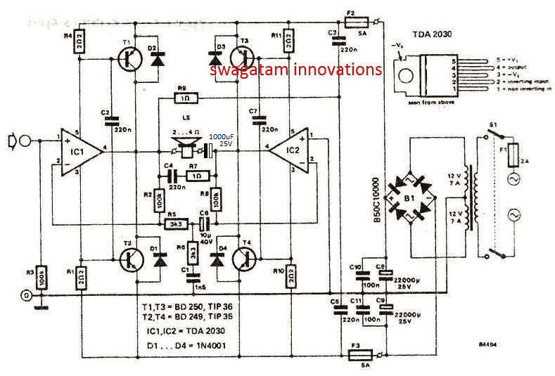
Image Courtsey: Elektor Electronics
The complete circuit diagram for the proposed BTL 120 watt amplifier circuit using two TDA 2030 ICs can be seen in the above diagram.
Circuit Operation
IC1 and IC2 are the two TDA2030 ICs rigged in a bridged tied load configuration which means the these two IC s now conduct in tandem in response to the high and low amplitudes of the input frequency and drive the loudspeaker in a powerful push pull mode.
For example when IC1 output may be delivering a high output to the speakers, IC2 simultaneously would be delivering a low output and vice versa enabling the required push pull action on the loudspeaker. This means the loudspeaker would be alternately operated with maximum positive and negative supply levels, causing the loudspeaker to work with double efficiency level compared to the normal amplifiers which are not BTL based.
The BJTs T1---T4 are included to boost the current level of the amplifier upto the specified 120 watt RMS, since the IC1, IC2 alone wouldn't be able to do this.
The NPN/PNP output BJTs also complement the BTL topology and help the ICs to achieve the specified amount of power on the loudspeakers.
The various resistors and capacitors around the speaker are introduced to suppress and filter the final outcome on the speaker, and to produce a clean and distortion free audio on the speaker.
Dual Power Supply for the Amplifier
The power supply for this 120 watt BTL amplifier using TDA2030 ICs is derived from a 12-0-12V / 7 amp transformer. whose output is rectified using a bridge rectifier and filtered using the indicated capacitor C8---C11.
The power supply produces a dual +/- 20V / 7 amp output which is mandatorily required for most BTL based amplifier circuits.


Questions & Answers
Hey, thanks for this. Do you have a BOM for this? I’d like to build one.
Sorry, I do not have a BOM, but you can easily create one by referring to the circuit diagram. All the resistors are 1/4 watt rated
Hallo am happy to be here. thanks for the nice schematics. They have been of great help.
Thank you, I am glad to hear that!
Please am a first year student in computer engineering, I have a project work to build an amplifier. Can you help me out? Please.
Hello, what is the quality of audio compare to TDA7294. What would be your personal preference?
It’s almost the same because both are equally advanced audio amp ICs
I very much enjoy these informative posts, Swagatam. I noticed another similar build to your above schematic here: https://www.electronicshub.org/200watt-audio-amplifier/
Nearly an identical schematic. The lm1875t is fairly much a drop in replacement for the tda2030 from information I have seen but I also would like to use mj15022/mj15023 for the output transistors.
I have an 18v split supply and want to use just one side of this bridged configuration, (single op amp and pair of output transistors) with the other side of speaker connected to center tapped ground.
I was digging around for some schematic of this type for a while knowing that there must be some way to use an op amp to drive a pair or more of output transistors, but I did not suspect the respective base connections to be wired directly to +vcc/-vee. It looks like your schematic calls for a 2 ohm 2 watt resistor limiting current to the IC and transistor base connections, while the other schematic calls for 1/4 watt 2.2 ohm resistors. Either schematic it appears both transistors are wide open at all times with diodes blocking what could possibly be a constant dc current drain? Not sure exactly how this circuit works, I am new to this field. I am guessing that the output of the IC from pin 4 in any positive range gets amplified through the npn power transistor, while negative signals get amplified through the pnp power transistor via power thresh-hold at their emitters. No voltage at the emitter = no current through the transistor.
Wish me luck with the lm1875t and mj15022/mj15023 project, going to try 12-0-12 for the first run but suspect that would be underpowered.
Thanks John, Glad you are liking my work!
Honestly, I have always found it tough to understand audio amplifier circuits and their configurations, the same goes for this design too.
The only vital thing I know about it is that its a BTL type of amplifier which works in a push pull manner for maximum efficiency.
For your present requirement I think the first diagram from the following article might help. It shows a simple design for using an opamp to drive a loudspeaker via a couple of driver transistor.
https://www.homemade-circuits.com/spy-bug-circuits/
I wish you all the best!!
Mr swagatam, please advise me on which circuit I can go for. I need an amplifier circuit that can be used in a room of 25 x25 m night club
Hi Emmanuel, you can try the following circuit, you will have to make two of them for a stereo effect:
https://www.homemade-circuits.com/40-watt-amplifier-circuits-using-transistors/
Sorry to sidetrack the discussion, but I found this after a lot of searching, and the setup intrigued me some. So if you have the time and chance to help me understand this, I would greatly appreciate it.
https://www.brighthubengineering.com/commercial-electrical-applications/57202-what-is-a-speaker-crossover-network/
I would like to try building it, though I realize some of the values are a little cryptic to me. So I liked to ask to make sure;
L1 – 3.00 mH?
L2 – 10.00 mH?
L3 – 0.25 uH?
L4 – 2.00 mH?
L5 – 0.10 mH?
C1 – 100.00 uF? mF? (this is listed as 100 Ω. Though I am not familiar with counting Capacitors by ohm?)
C2 – 33.00 uF
C3 – 10.00 uF
C4 – 6.00 uF
R1 – 10.0 Ω (10W)
R2 – 5.0 Ω (10W)
R3 – 2.0 Ω (3W)
R4 – 10.0 Ω (5W)
R5 – 3.3 Ω
R6 – 6.0 Ω
The 100 ohm is a typo, it is supposed to be 100 mH.
The design was taken from elektor electronics magazine so most probably this would work as intended.
thanks for all d knowledge you share us. we really appreciate it sir more grace by God’s grace. Is there any 400watt amplifier in your box.
You are welcome toba!
please sir the last capacitor that you added 25V 1000uf sir what is the function? any special name given to such capacitor arrangement.
It is a standard electrolytic capacitor, it is positioned to stop overloading of the speaker and to block DC from entering the speaker
pls how can I reduce or remove d humming sound due to the usage AC power but I power it with battery it was cool and clean sound. thanks so far sir
try increasing the filter capacitor value to a level which almost eliminates the noise, otherwise you may have to incorporate a notch filter, as explained here
https://www.homemade-circuits.com/designing-notch-filter-circuits/
thanks here I have made it and it worked as I want. I make the switch at the primary side but I build a transformerless circuit to power the relay and 4017 ic. thanks for the knowledge you are sharing always! stay blessed
You are most welcome! I am glad you could do it with such ease!
…and connect the +/- supply lines of the amplifier via the pole and N/O contacts of the relay….
I understand what you are saying. thanks so much. I want you to help me select d best *wattage* amps that I should build with it that voice will come out clean that ll feet with 120watt sub woofer cct…. sir how can I measure wattage of an amp? thanks in advanced.
thanks jesubiyi,
you can try the following concept for measuring power of amp
https://www.homemade-circuits.com/make-this-amplifier-power-meter-circuit/
you can use the following circuit for making a good power amp
https://www.homemade-circuits.com/how-to-make-simplest-100-watt-mosfet/
” so it is better to put the switch at the primary side only….twin switch won’t be required, just a single SPDT will be enough at the primary side.”
thanks for the light. I have a reason with you. I make small transformerless cct to power the relay and 4017ic and make the switch at the primary side. DPDT relay is not available yet.
sir please I want to include switch to ur cct but I don’t want it at d primary side of xformer. am confused which place to place my switch Bcos here is two voltage source. -ive and +ive &grnd .fear here… I don’t want to burn my ic… sometimes I don’t use to unplug it till Lite goes. lite may come over mid night heavy sound wake everyone up. I Don build toggle switch with 4017ic. that ll reset d relay off (NC) until I press d switch on.
Jesubiyi,
for the secondary side you can use a DPDT relay, connect its coil via one of the supplies of the trafo…and connect +/- supplies of the relay via the pole and N/O contacts of the relay….
However switch should be always at the primary side so that the transformer also gets switched off, otherwise your transformer will be always ON and consume some current even while the amp is switched OFF, so it is better to put the switch at the primary side only….twin switch won’t be required, just a single SPDT will be enough at the primary side.
correction:
…and connect the +/- supply lines of the amplifier via the pole and N/O contacts of the relay….
“
note.
if u want good output add 25v 1000uf cap in series with d speaker and it also protect ur ic. and also never use same heat zinc for all ic and transistor .Q1, Q2 can be together on a heat zinc and Q3 ,Q4 on another zinc also different heat zinc for each ic .if u use it, it means u hv short cct d output. d ic is grounded to heat zinc already and transistors collector shouldn’t be connected on the same heat zinc. I wish u good luck…please u cn add it up in d write up @ swagatam .thanks in advance
Thank you very much Jesubiyi, appreciate your concern and the notes….
pls direct or gv me an 2030 amp cct that can be used for sub woofer cct without center tap transformer. which I can power it wit 12V 7AH battery
I will do some online search and update it if I happen to find the required design…
i have 2 transformers—–same type—–15 v 6a —each———
can i join the 0 v of each to make dual rail supply of 15-0-15 v 6a for amplifier ?
——–thank you
that may no be possible because the phase direction can be different in their winding and will need to be matched before connecting, I am not sure what can be the consequences if it is not matched.
ok
in ab amp as tda 2050—–when i play songs—i usually do not raise volume above 50%——–it becomes too loud————but in english 5.1 movies downloaded from internet—most of time aac audio———–volume so low——-i have to put 100% volume———to make it equal to songs sound level earlier written———–both cases sound decibel approx same—-
1————-in these 2 cases–what do you think in which case power output will be more ?
2——–i dont have ac meter to measure current—basic multimeter measure ac volts, dc amps/volts——-can i measure ac current of amp output with dc multimeter ?
————thank you
you can compare the current by measuring it in series with the DC supply to the circuit….if the input source is low, the amplifier will also generate lower output.
thank you
i made 6 mono amp boards tda2050(fake ics very cheap rs 15)——working sounds very nice good power for my 3 way tower—-FUSE I HAVE GIVEN FOR SPEAKER PROTECTION
but i have a weird tention going on my mind—–
if amplifier fails suddenly like –inner transistor of chips shorts or overheating or some weird(USING FAKE ICS SO I GUESS THEY DONT HAVE ANY INNER PROTECTION) reason———IS THERE ANY CHANCE BY WHICH MY INPUT SOUND SOURCE DEVICES AS DESKTOP PC OR MOBILE GETS DAMAGED ?
IF SO THEN PROTECTION———
——–THANK YOU
you can use an LM35 relay circuit and use it to switch OFF when the temperature exceeds a certain level:
https://www.homemade-circuits.com/lm35-circuit/
Hi swagatam.thanks for replying….I am not getting bd series transistor…..can I use 2sc 5200 &2sa 1943 toshiba.
Hi Waqar, Any transistor will work, just make sure the emitter-collector voltage and the maximum current handling capacity of the transistor are adequately higher than the maximum supply voltage of the amplifier.
Thanks…a lot……send some project for microcontroller burners
please provide the requirement specs more elaborately. I’ll try to get it..
Hi sawagatam……can we use 2sc5200&2sa1943….transistor in place of Bd250&bd249 what difference in output wattage…….I am not getting bad series transistor……
Hi Swagatam please send modified updated ver of this Amplifier With capacitor in series and lm 1875 also works well .it has same pin configuration…or give some hint to update….thanks
Thanks Waqar, I do not have much idea about the other IC, if you think the pinouts are similar, you can try configuring them in the same fashion as above and see if it works, ….will be great if you could update the results here 🙂
pls give me best fit sub woofer cct that I can couple to it. thanks in advance God bless you
you can refer to the first 3 links in the following page and build the subwoofer from the given information
https://www.homemade-circuits.com/?s=low+pass
thanks for the update. well-done boss
you are welcome!
I have built d this same cct with all d component stated but I found out that on d connection of d speaker something is wrong . guess what happened I smell magic smoke through the speaker and a lot of heat was been generate on each heat zinc so I try to measure voltage and it’s 15v+… what I did was I added a cap 1000uf series with d speaker. that’s my solution and it work. or any better suggestion sir ?thanks to great icon swagatam
yes I think you are right. because normally when we operate a single IC we employ a series capacitor otherwise the speaker and the IC can get shorted.
I will update the circuit soon with a capacitor…thank you for this useful information.
Hi Swagatam, hope you are doing well. BTW is this amp truly a 120-RMS or 120-Watt, lastly I can replace the two TDA2030 with a TDA2050. Thank you. Regards.
My pleasure!!!
Thank you Swagatam, you are a great man. Regards.
OK great, no problems then!!
Yes it is. I have checked their datasheets and they are almost same, the only difference is TDA2050 has a higher input voltage and more wattage power on the output. Some few months ago I have replaced TDA2030 with TDA2050 on my old PC woofer and it still works like a charms:) Thank you. Regards.
You are most welcome Lima!! hwoever I am not sure whether TDA2050 is pin to pin compatible with TDA2030 or not.
Thank you so very much for your time and help, greatly appreciated:) OK this will be my project for this season:) but I will be using TDA2050 instead of TDA2030. Regards.
Hi Lima, it is 120 watt RMS, because along with the IC the load is also handled by the external BJTs, which allows the design to run the specified amount of power continuously without any problems.
please mention the wattage of the resitors and the voltage raings of the condensors along with a pcb for the 120w amp
non-polar caps can be all 100V rated and PPC type.
when not mentioned, you can always assume them to be 1/4 watt 5% CFR
I would want to use it for car audio since its single railed. Normally removing the transformer and the power supply stage should do the trick but I realize in this circuit the transformer center tap has made a few connections, IF I was to to run this from just a 12v battery that means I could just replace the center tap connections with battery negative?
No that may not be possible, you will have to use two 12V bats in series, and use the series joint as the ground for the amplifier, this will replace the center tap rail of the trafo.
and the +/- from the battery can be used for (+) and the (-) supplies of the amplifier.
Was this circuit tested
yes 100% tested