In this post I have explained how to configure a couple of LM380 ICs in the bridged format to create an output power that's two times more or double of a single IC amplifier.
When two identical amplifier circuits are configured such that the loudspeaker operates at the center in a push pull manner, between the outputs of the two amplifiers, it is called a bridged amplifier circuit.
Many handheld radios or cellphones provide a power output that hardly ever goes beyond 100 milliwatts into the connected loudspeakers. Although this power may appear completely satisfactory for regular listening, lots of people realize that it is simply insufficient when these kinds of devices are used in a cars or in picnics and outings.
Nevertheless this issue could be solved employing a little booster-amplifier which could give the required extra power to the loudpseakers. This kind of amplifier can be operated through the 12 volt battery supply and able to take an input from any earphone socket, or line out socket of the radio, USB, or any cell phone.
The proposed booster amplifier is configured in the form of a bridged amplifier circuit using the IC LM380, and has been built to amplify small signals into large boosted output over the connected loudspeaker.
The circuit works by using the low-cost LM380 ICs. A couple of LM 380 ICs can be seen connected in a bridge configuration that generates an output power of approximately 5 watts RMS by suing a 12 volt supply and a 8 ohm speaker).
How it Works
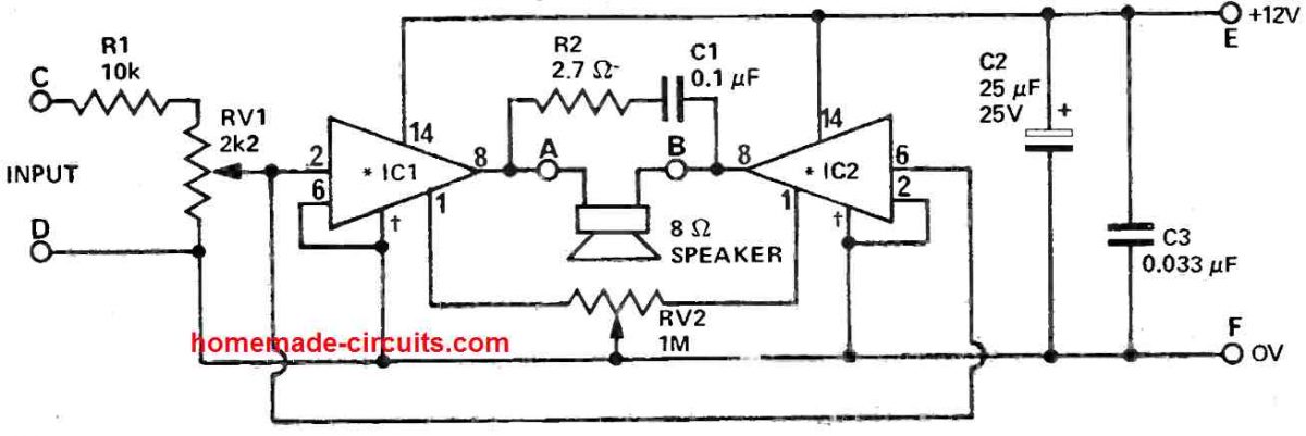
The IC LM380 is an integrated audio amplifier that, provides a constant gain of 50 (34 dB) and, could be hooked up in either inverting or non -inverting mode (meaning output can be connected in the 'out of phase' manner or 'in phase' with respect to the input signal source).
A pair of of LM380 ICs can be seen wired up in a bridge configuration to enable increased power output using a rather lower power supply voltage of 12 V.
To accomplish this, we operate the two amplifiers using the identical input signal. However we link the common signal one with the inverting, and the other with the non-inverting modes of the amplifier.
The loudspeaker is then hooked up between the two bridged LM380 amplifier circuits, so that it can consequently get two times more output amplification compared to a single IC. The input necessary for 100 % power output is approximately 50 millivolts.
Therefore an input attenuator can be seen included in the design to boost the input specification to around 1 volt so that it allows the user with a preset adjustment to accommodate the majority of the signals from radios, USBs, or cellphones.
We can be see a trimpot on the PCB provided for tweaking the sensitivity of the bridged amplifier so that complete volume range becomes available for the volume control of the source signal, with around 50 % rotation of the trimpot.
If it becomes necessary, a separate potentiometer could be employed instead of the preset for the volume control implementation. The IC's output voltage will be about 50 % of the supply voltage.
Remember that, because the loudspeaker is connected directly, any minor variation in the outputs of the amplifier will cause a dc current to enter into the loudspeaker.
Construction
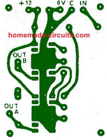
All the parts must be assembled over a a small PCB as indicated in the component overlay picture. The LM 380 ICs, can be seen positioned in line, such that it becomes possible to use a common heatsink that could be connected to the two ICs on each side. Each of the heatsink must be a minimum of 25x50mm in size and must be made of copper or aluminum plate.
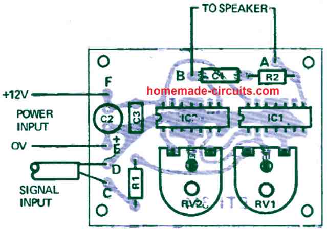
As can be seen in the layout diagram, the a pair of variable resistors or presets are given for setting up the amplifier. The, RV1 which is for adjusting the volume of the amplifier should be tweaked according to the output voltage available from the music source which is being amplified.
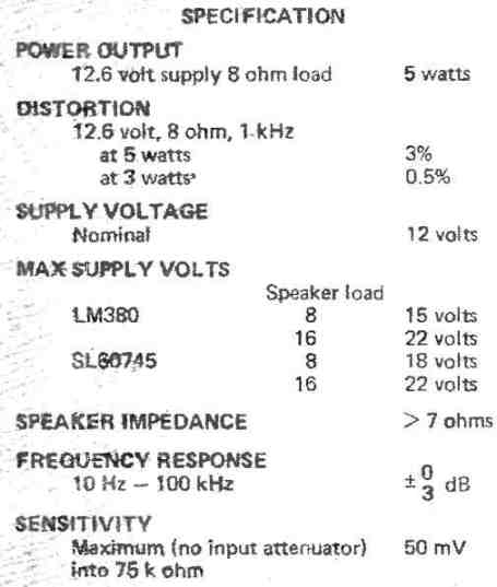
The sensitivity spec of this bridged amplifier circuit will be 5 watts output will be when with RV1 is adjusted at its maximum sensitivity level, with an input signal level of 50 mV. This input level should be totally sufficient since many radios might deliver higher than 200 millivolts.
The second variable resistors which is for the balance control must be adjusted to get the lowest DC into the speakers as explained in the following paragraphs.
How to Set up
The trimpot RV2 must be set up, by referring to a multimeter, to get a zero volts across the loudspeaker points A and B (or try getting minimal current through the input supply).
Another manual option could be, to make and break one of the loudspeaker wires while simultaneously adjusting RV2 until the 'clicking' sound from the speakers fades off or becomes almost inaudible.
Specifications


Questions & Answers
Very interesting circuit with minimum components count. I have decided to assemble this circuit and would like to know whether the ics are operating in class A mode.