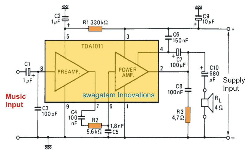
A very simple yet useful 6 watt audio amplifier circuit using IC TDA1011 is explained in the following article, which can be built by new hobbyist and used for amplifying music from different sources such as cellphones, FM radios, doorbell etc.
By:Dhrubajyoti Biswas.
A monolithic integrated audio amplifier circuit TDA1011 is especially used for recording systems or portable radio. TDA1011 has the power to delivery up to 4W on an impedance of 4W load.
The device can also reach 6W on 4W where the supply would be 16V in those applications which are mains-fed.
The maximum permissible supply of TDA1011 is 24V. It is for this reason the device is well suited for AC and DC systems.
Also the low voltage supplies of 3V and 6V enables applications that run on 6V.
TDA1011 comes with various features.
They are:
a) SIL based which enables easy-mounting of the device;
b) power and preamplifier is separated;
c) output power is high;
d) has thermal protection;
e) input impedance is high;
f) current drainage is low;
g) generates less noise to radio frequencies.
Technical Specifications
Other electrical specifications for the proposed 6 watt amplifier circuit using TDA1011 are as follows:
- Peak output current is as high as 3 amps
- Total Harmonic distortion is 1.5 watts
- Frequency Response is within 60Hz and 15kHz
Heat Sink Design
Just like any other amplifier IC, the TDA1011 too will require a heatsink in order to perform optimally at full load conditions, that is high volumes.
Let's assume the supply voltage to be 12V, then as per the standard calculation a hetasink of 39 K/w would be just enough for keeping the IC col and running faithfully regardless of the load conditions.

Questions & Answers
como posso colocar potenciômetros no circuito?
Do you want to connect a volume control pot?
when signal cable open——–noise stiill there
1) The volume control should be from the amplifier side and controlled from the amp side and not from the tone controller side… otherwise the noise issue will be always present
2) use good quality SHIELDED wire from the tone controller to the amplifier, and make sure the shield of the shield wire is correctly grounded with the amp ground.
3) unregulated power supply will work but it must a pure DC and within the specified limits of the circuit.
should i connect grounds off both amp, preamp transformer ?
——-actually amp trannsformer 22-0–22=44 v so i cannot use in preamp
all grounds should be connected in common, that’s compulsory for any DC circuit work….
picture———–https://ibb.co/bHm1pw
———–does this pic makes clear to you connections———–amp is grounded to amp transformer ————
signal grounded to tone board transformer——–tried grounding too amp transformer—-no result———in the pic———–+-g is supplied by 12-0-12 v dc from unregulated supply using transformer-bridge-caps———
input—–is given from pc out–input is grounded to gr of power—-output connected to amp input
I hope you understood what I meant by shielded wire….in the image I can clearly see you have not used a shielded wire for music input. better do it if want to reduce noise pick up…
+ supply can come anywhere but the ground line must be connected in common for the DC stages.
does it works on unregulated supply
my amp do not consist of vol knob——–pc out set to full vol——-i adjust vol by tone board
photo sort of this type–
———without regulator———-i have unregulated supply
also vol pot–47k, bass trble mid–100k
i have tda 2050 stereo made by me—working fine no noise——i buyed–readymade–tone control board bass,mid,treeb,vol–2 ic —–4558d—-pho
power supply separate is for tone board—
9-0-9 v ac after bridge rectify—-12-0-12 v dc power given to tone board—-in board written d c—-( + – gr)
observations—-
1——-when i connect tone board—sound ok but huge background noise also when pause song huge background noise —-noise decreases if vol turned down
2———weird thing in tone board—vol increases if i turn anticlock direction, all other pots increase anticlock direction
3——–when i turn off power to tone board with amp on no noise
4—–in board power ground, input,output,vol pot same ground
5—–in input of tone board 150 k ohm there—output 10k
6————-tried star grouunding for amp,signal,tone—–noise there
——–what should i try to resolve issue ?
———–thank you
How did you connect the tone board with the amp?….make sure either the tone board is directly attached with the amp volume or if it is through a cable make sure it is a shielded cable…and the shield of the cable appropriately grounded with the ground of the amp.
to correct the volume orientation of the tone, just interchange the outer wires of its volume pot….
in input of tone board i have given pc out right/left and ground—-in output of board connect to amp input right /left tda board and ground together