In this post I have explained how to make an electronic stethoscope amplifier circuit for enabling a loud audible reproduction of the heart beats which is being diagnosed.
The article also reveals how the same can be applied within a cellphone through a wireless circuit. The idea was requested by Dr. Ankit.
Main Requirements
- I would request you to help me with the following circuit "An Electronic Stethoscope".
- Significance- An ordinary stethoscope is a device used to listen to breathing and heart sounds. A hollow rubber tube is connected at one end to a disk shaped diaphragm (placed over the patient) and other end connected to as Y shape to the ear of listener.
- As breathing and heart sounds create slight vibrations, these make the diaphragm vibrate and then the sound is amplified in the disk and audible through the tube to the other end.
- In hospitals, often there is noise of other equipment hence the weak sounds transmitted by stethoscope are sometimes inaudible and important diagnosis missed by the listener.
The Objective:
A circuit is requested that picks up sound vibrations from the diaphragm of the stethoscope and convert it to electronic signals that are then amplified and can be heard through a speaker loud enough that connecting to ears is not required and no sound is missed (even by less experienced practitioners).
The battery utilized may be small lightweight 4.5V or 6V (like ones used in rechargeable led torch) OR through mobile power banks since stethoscope must be portable and easy to carry at the same time avoiding wall socket connections for power supply.
As an improvement of this circuit - If possible the circuit may derive power through an android phone directly AND again if possible the output signals may be visualized as a graph in the android screen.
As there is no direct contact with ears, this will also prevent cross infection of ears as sometimes happens when one stethoscope is used by multiple users.
The Design
The sound of a heart beat can be extremely weak and therefore it cannot be heard without a minimum suitable device such as a stethoscope.
A stethoscope is a basic device which relies on picking and transferring the air vibrations through a tube into the ears of the user.
The vibrations are caused by the heart beats on the stethoscope's sensing diaphragm when it is brought at a close proximity to the chest where the heart is situated, and the diaphragm movement sets the air column inside the tube into a correspondingly push-pull vibrating motion
This surely means that even though the air vibration or the sound vibration generated by the heart could be small enough but it's loud enough to be heard without the aid of electrical device, which implies that the sound may be sufficiently strong to be amplified using an audio amplifier, because if a naked ear can hear these minute vibrations so can the amplifier MIC.
Producing Heartbeat in Loudspeaker
In order to reproduce the sound over a loudspeaker, the signal needs to be amplified significantly and also in the course it must be suitably processed to remove any associated disturbances.
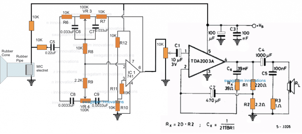
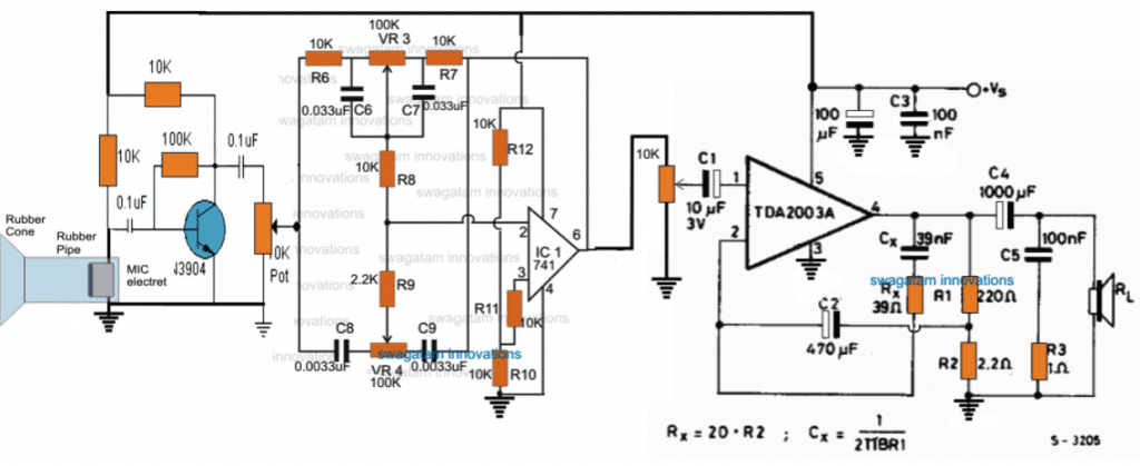
The circuit diagram of the proposed electronic stethoscope amplifier is designed using two stages, one consisting of the opamp based tone control circuit, and the integrated proper amplifier stage.
The tone control stage is built around the opamp 741, and with the help of the associated RC networks and the pots.
The upper pot controls the low frequency limit, while the lower pot is used to control the upper frequency limit. Both these pots can be appropriately set for achieving the best possible sound clarity.
In addition to the sound processing, the opamp stage also acts like a preamplifier for elevating the very low amplitude of the heart beat pulses to a suitable level for the power amplifier input.
This enables the power amplifier to pick the signals at above the required minimum detectable level and amplify it on the loudspeakers optimally.
MIC as the main Sensor
The main sensing stage of this electronic stethoscope circuit is formed by an electret MIC which can be seen configured across the input of the tone control stage via an RC network.
In order to enable the MIC to sense the minute heart beat signals, the mic is enclosed within a rubber pipe with a rubber funnel like mouth opening.
The funnel like opening is supposed to be stuck over the chest of the patient just above the heart area for allowing the MIC to detect the concentrated heart rate sound and convert it into minute proportionately pulsating electrical pulses.
The opamp circuit responds to these signals and processes it appropriately as per the setting of the low pass and the high pass filter pots.
The finalized signal is applied to the input of the power amplifier configured around the TDA2003 amplifier circuit which is capable of generating a strong 10 watts of amplification over a 8 ohm loudspeaker.
The pot between the 741 output and the TDA input determines the volume of sound and can be adjusted for the same.
You May Also Want to Learn the Construction of a Bluetooth Stethoscope Circuit
Convert Heartbeat Sound to Loud Thumping Sound [Tested]
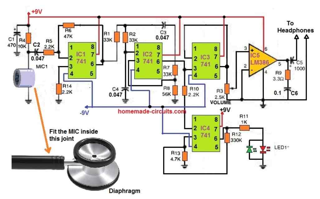
The next circuit shown above is a tested design which is able to convert a heartbeat sound into loud thumping sound over headphones.
In addition to amplifying heartbeats to thumping levels, this circuit seems to be more enjoyable with headphones because good headphones help cancel out background noise.
Also, an active lowpass filter helps the stethoscope's diaphragm frequency response to create a superb overall acoustic quality.
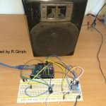
We tested with several diaphragm, bell, and hybrid stethoscope instruments in a wide range of levels, from cheap to costly, when building this circuit, and the results were astonishing.
The mid-frequency response of a simple diaphragm head is superior to that of a bell shape, and it produces reduced background noise.
Additionally, a less costly diaphragm operates practically as effectively as a costly one; perhaps the electronic circuitry is responsible for this balancing.
How the Circuit works
A couple of 9-volt batteries (or 9-volt AA battery packs) are used in a dual supply to provide the DC power to the circuit.
Make absolutely sure the batteries are new to avoid performance issues. Layout and design of the circuit components are not important.
The IC1, an LM741 integrated circuit arranged as a gain amplifier, is capacitively hooked up to the microphone output.
The IC1 output is supplied into IC2, which is a second 741 setup as a lowpass filter.
The cutoff frequency is little above 100 Hz with the resistor values R1 and R2 as indicated in the schematic (33k), which, according to our detailed evaluation, provides the overall optimum response.
You can achieve an variable output response by replacing R1 and R2 with ganged 50k or 100k potentiometers, but you might most likely end up keeping these settings tuned in the 30k range eventually.
Be careful when selecting much higher cutoff frequencies because they increase the circuit's sensitivity to feedback and cause the diaphragm on your patient's chest to sound like an explosion (really uncomfortable with headphones!). Next, the filtered output from IC2 now divides into IC3 and IC4.
Another 741 is used as a buffer for the low-voltage audio amplifier, while IC5 is an LM386 IC that operates the headphone speakers.
R3's potentiometer adjusts loudness.
Since the output impedance is 4 ohms rather than 8 ohms, when typical 8 ohm stereo headphone speakers are combined and operated in parallel, the LM386 is perfectly capable of handling this situation.
Returning to the output circuitry, IC4 is a second 741 that has been set up as a gain amp and has been specifically designed to drive a bipolar or two-color LED, which produces a very intriguing visual representation of the heartbeat.
High Precision Electronic Stethoscope Circuit with PCB Design
How does it work?
This high precision electronic stethoscope circuit consists of two parts: the microphone and the amplifier. Let's start with the electronic part.
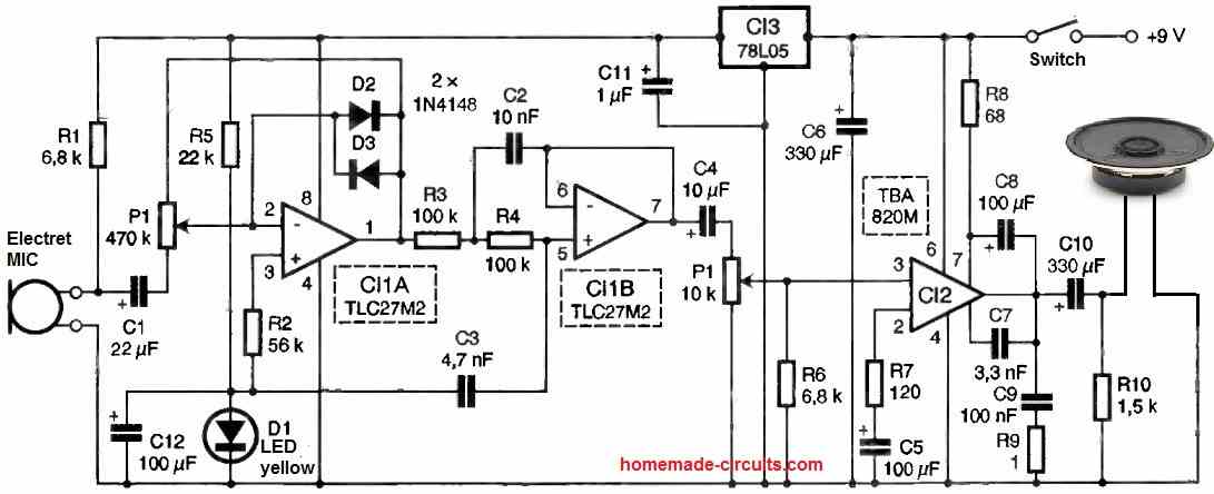
We begin with a preamplifier built around IC1A. The integrated circuit is used as an amplifier, and the gain can be adjusted by the two resistors located on either side of the slider of potentiometer P1.
The microphone is an electret type and is polarized by resistor R1. Capacitor C1 has a relatively high value. Heart sounds have a relatively low frequency, and they are also impulsive in nature.
The two diodes D2 and D3 limit the output voltage amplitude and prevent saturation in case of impact on the microphone.
The circuit is powered by a 9V battery, and a 5V regulator supplies power to the dual operational amplifier IC1 and the microphone with a voltage that is not dependent on the sound level.
The circuit is biased by a yellow light-emitting diode (LED), and the internal resistance of this component is reduced by capacitor C12.
IC1B is used as a second-order low-pass filter in a Sallen and Key configuration. The cutoff frequency is 200 Hz, prioritizing low frequencies.
As an experimental option, one can also play with changing the cutoff frequency to listen to sounds outside the chosen 200 Hz range.
The biasing of this stage is done directly through the output of IC1A, and resistors R3 and R4 provide a direct connection for DC. We use IC1, a UNCMOS amplifier with almost zero bias current, so there is no voltage drop across these two resistors.
The filter is followed by a power amplifier using a TBA820M, which is a classic circuit surrounded by the usual collection of resistors.
R6 helps maintain input bias in case of poor contact with the potentiometer slider. The potentiometer itself will be a logarithmic model.
The two contacts of the stereo output jack are in parallel, so we have mono headphone listening here, with both earphones connected in parallel.
Resistor R10 is used to charge capacitor C10. If we connect headphones that are already on the ears, there will be no charge in the earphones, therefore no harmful or unpleasant noise.
The microphone is of the electret type, but as it does not provide efficient capture of body sounds, we have modified it to change the active surface of the membrane, as we will see.
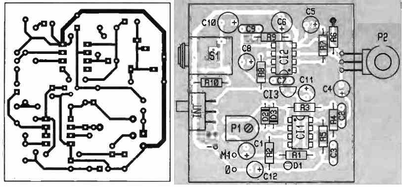
PCB Designs
A Simpler Alternative (using a Wireless FM Transmitter)
In the request we also see the mentioning of a android phone compatible unit, which is difficult to achieve using the above circuit since the minimum operating voltage of this circuit can be over 12V so it cannot be operated easily using a cellphone existing battery
A simpler yet a more advanced method for achieving an electronic stethoscope amplifier functionality with a cellphone is to go wireless.
A small FM transmitter circuit can be used and positioned near the chest of the patient, and the heart pulses can be heard or recorded loud and clear over any cellphone equipped with an FM radio, which is commonly included in all standard cellphone regardless of its sophistication level.
The mic will need to be encapsulated appropriately inside a pipe/funnel kind of enclosure as suggested in the previous discussion, so that other forms of disturbances become undetectable for the MIC.
Once the heart beats are recorded inside the android phone, this can be easily used with a suitable app for converting the same into a graphical format and for enabling a more scientific assessment of the patient heart condition.
The wireless stethoscope amplifier circuit set up can be understood from the following diagram
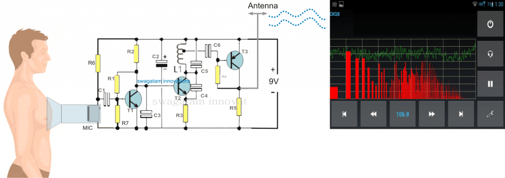
Parts List
- R1 =1M,
- R2 = 2K2,
- R3 = 470 Ohms,
- R4 = 39K,
- R5 = 470 Ohms,
- R6 = 4k7
- R7 = 270K
- C1 = 0.1 uF,
- C2 = 4.7 uF,
- C3, C6 = 0.001uF,
- C4 = 3.3pF,
- C5 = 10pF,
- C7 = 100uF/16V
- D1----D4 = 1N4007
- L1 = See Text
- T1, T2 = BC547B,
- T3 = BC557B
- TR1 = transformer, 0-9V, 100mA
Feedback from Mr. Jan
I have built this project and it works well as a normal amp, but it is not sensitive enough to pick UP any heartbeats.
Any suggestions as to how I can make this more sensitive? Your assistance will be much appreciated.
Solving the Circuit Query
My Response: The design explained above needs to be correctly optimized in order to get the most favorable results, however in order to enhance the outcome to maximum, a transistorized MIC preamp could be introduced at C5, as illustrated in the following diagram, this should hopefully make the proposed electronic stethoscope circuit extremely sensitive and enable the heartbeat to become loudly audible.
Jan:
Thank you for the update.
I have made the changes and must admit that it is much more sensitive, although I still cannot pick up a heartbeat clearly. I think the problem might be with the microphone.
Question: Are all electret microphones more or less the same or do you get some that are more sensitive?
Analyzing the Circuit Results
Thank you Jan,
Electret Mics are all similar with their specs according to me, they will behave identically unless the device is faulty or accidentally a duplicate low quality piece.
I think you will need to fine-tune the circuit for getting a proper optimal response from the output.
For this first you must replace the speaker with a headphone so that the initial low un-optimized sound becomes slightly audible in our ears.
Once you get hold of the sound you can begin adjusting the bass treble pots until the most favorable sound becomes available in the headphones, later on once the audio is perfect the headphones can be replaced back with loudspeakers.
If you find the existing bass treble stage inadequate, you can replace it with the following 10 stage equalizer and get an access to a 10 level optimzation control.
https://www.homemade-circuits.com/2013/06/10-band-graphic-equalizer-circuit-for.html
Best Regards.
Warning: The concept has not been verified for its accuracy and credibility and the author does not in any manner endorse the use of this circuit for serious heart diagnosing. Consult a qualified medical personal before using the explained circuit practically on a patient.
Listening to Heartbeat on Loudspeaker
This straightforward circuit, if attached to an audio amplifier, enables you to hear your heartbeats.
The op amps's low frequency gain is adjusted by means of R1 and R3, together with VR1 and R4. Preset VR1 makes it possible for the gain to be adjusted through a range of 60-80 dB.
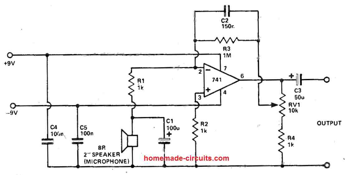
C1 and C2 generate a bit of low frequency cut, lowering 50Hz pickup while the capacitors C4 and C5 alleviate problems with instability due to the circuit's high gain.
The output of the circuit must be hooked up to the input of an audio amplifier which must include a bass adjustment feature. The bass pot must be adjusted to a high point for getting the best possible heartbeat sound response.
Efficient Stethoscope Preamplifier Circuit
Want to diagnose your heartbeat and listen to it closely? Using a small 50 mm loudspeaker, we're turning it into an unconventional microphone.
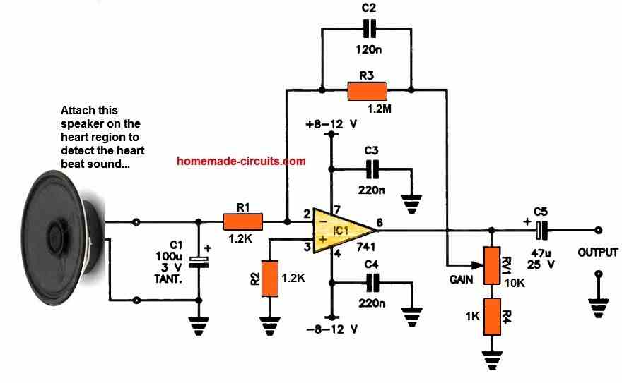
We've set it up to boost the low-frequency heartbeat sounds while reducing the other external high-pitched ones.
This clever circuit acts as an efficient preamplifier for a stethoscope, allowing you to amplify heartbeats before connecting to an audio amplifier.
You can control the level of amplification using Potentiometer RV1.
Capacitor C1 helps smooth out the high-frequency response from the speaker microphone, while capacitor C2 fine-tunes the op-amp's high-frequency gain.
You can now connect the output of the above circuit to the input of any audio amplifier for loud amplification of the heartbeat sound.

Questions & Answers
What does this “A couple of 9-volt batteries (or 9-volt AA battery packs) are used in a dual supply to provide the DC power to the circuit.” Mean in 4 741 ICs circuit? Do we have to connect 2, 9v batteries in parallel or in series? Or do we have to give 9v to the upper 4 ICs and a separate 9v battery to power the lower 741 IC as mentioned in circuit diagram?
You will need two 9V PP3 batteries connected in series. So, the (+) and (-) end terminals of the series battery becomes the +9V, and the -9V supplies, while the series connection of the two 9V batteries can be used as the GROUND for the circuit.
Please see the following image:
https://qph.cf2.quoracdn.net/main-qimg-26458b88044d4b939f5ea985810e87d8
I’ve used 2, 8ohm speakers in the output of my electronic stethoscope circuit(using 4, 741 ICs). Can u refer what kind of speakers should I use for perfect circuit working and output?
If your circuit stages are working correctly, then any small 8 Ohm speaker will work, or even headphones can be used.
I’ve done the same but my circuit is not working (Only red LED is lit). Can I get your email so that I can share pictures of the circuit with you and if you can guide me through?
The circuit using the 4 IC 741 and Lm386 has many parts and many stages and it can be difficult for me to troubleshoot your circuit because I don’t how you have built it and the other issues in it.
Ok thanks.
Is there a device / app that can be ordered to make the breathing/heart beat audible without ear tube? This DIY exercise would take quite a bit of time…
Did you search this on amazon? I think it should be available on amazon or flipkart.
I did look for it, indeed. Actually before I found this page. It shows me plenty of stethoscopes; a few “digital” – a ‘stemoscope’ with bad reviews (not audible..).amazon.com/stethoscope-amplifier/s?k=stethoscope+with+amplifier
Yes that’s right, Even I could not find the desired readymade options.
in that case it would be better to build one at home. The last design looks easier, the output could be heard on an earphone.
Hi, I’m currently working on a stethoscope project which will capture heart sound and send to PC via Arduino for heart sound classifications. Do you the circuit in “Convert Heartbeat Sound to Loud Thumping Sound [Tested]” is enough for this? I need a rather clean waveform.
I have not tested the waveform for the “Convert Heartbeat Sound to Loud Thumping Sound [Tested]” so I am not sure whether it will work correctly for the heat sound classification or not?
Why have you used four 741 ICs in this circuit “Convert Heartbeat Sound to Loud Thumping Sound [Tested]” in addition to an audio amplifier, meanwhile the last two circuits utilizes only one 741 IC for apparently similar function? Is there any more precision or advancement in the output of the circuit that uses four ICs? Can you please tell the need to use four ICs instead of one?
The circuit using four IC 741 will have more precision and clarity. The function of the ICs are explained in that section below the diagram, you can read it for more details.
The last two designs are not so accurate and also they use a speaker as the MIC instead of an actual electret MIC.
Which electret MIC is best for high precision and sensitivity for electronic stethoscope project?
Any standard electret MIC will work.
Please Answer this question honestly: If you were to make a semester project out of any of the above electronic stethoscope circuits, which of these would you make? kindly tell the Title of that very circuit.
First of all these circuits are not easy to build, therefore they are recommended only for those who are well versed with basic electronics.
So if you are new to electronics then I would not recommend any of these circuits to you.
If still you want to try, you can try the last circuit. Test it with a headphone first, if you are able to hear the heartbeat sound, you can then connect the output with an LM386 amplifier, or any other small amplifier for producing the sound loud on a loudspeaker.
I am familiar with basic electronics and now studying “Amplifiers and Oscillators” for which I wanna design this as a project.
Ok, then you can try the circuit using four 741 ics, or the one which has a pcb design is also good.
The last two circuits are much easier but they use speaker as the mic.
Also specify the Farads of the capacitors used in this circuit “Convert Heartbeat Sound to Loud Thumping Sound [Tested]” (for example; only 0.47 is written) Idk what to assume, farads or microfarads?
The capacitors are all in “µF”
Can I get a detailed step by step video of this circuit “Convert Heartbeat Sound to Loud Thumping Sound [Tested]”?
And where to exactly fit the electret mic in the stethoscope in order to listen to the heart beat clearly?
Sorry, a video demo may not be available, since the circuit was tested a long time ago. The MIC can be fixed within the tube which connects the diaphragm section of the stethoscope.
EXCUSE HELP ME WITH A CIRCUIT AND THE WORKING PRINCIPLE OF THE ELECTRONIC STETHOSCOPE THAT ITS OUTPUT WOULD COMPRISE BOTH HEADPHONES AND SPEAKER THAT WOULD HELP THE MEDICAL PRACTITIONERS TO EITHER OPT TO USE HEADPHONES OR SPEAKER DEPENDING ON HIS OR HER PREFERENCES. KINDLY
You can try the circuit which 741 ICs. It is a tested design. You can use heaphones and speaker both in this design
Hi Swagatam, nice website, very interesting projects. At the outset I must tell you that I’m a medical doctor with basic electronic knowledge. Do you have full vacuum tube amp circuit based on the ubiquitous 6J1 or 6K4 vaccum tube commonly found in ebay? I have scraped the internet and found only preamp circuits. Not one pre and full stage amplifier. I know people will scorn me for choosing something highly in-efficient but that’s how I want it.
Thank you Samuel,
Glad you liked the website!
However, unfortunately I do not have any amplifier circuit which uses vacuum tubes.
If possible I will try to search on internet and post it for you if I happen to find one.
Hello!
I want to use this model for practice before completing a course project. If possible, could you give me a more detailed description of the operation of the electrical circuit, which will explain the role of each component in the circuit? Thank you in advance
Hello, giving the details of each and every component can be difficult and too lengthy. In short the circuit has 2 stages, a bass treble control circuit which also works like a MIC preamplifier and a power amplifier which amplifies the signal from the bass/treble MIC preamplifier to produce the audio on the loudspeaker.
Making a Stethescope Amplifier Circuit
Hello Swagatam,
greetings to you,
I some times fix my mechanical watches and would love to hear the beat of the watch Audiobly but unfortunately the beat of the watch is less than 30db, Does the above circuit sound suitable for my application, I have tried couple of circuits using the TBA820M, but sadly does not help.
Thanks & regards
Hello Patrick, yes definitely that’s possible. As long as your ear is able to hear the beats then the MIC will too, and amplify it to the desired levels,
The TBA820 must be preceded by a MIC preamplifier, then the output will be audible.
Thank you Swagatam, I had attached the Preamp circuit to the amp, but the output is very feeble. Hence want to try the above circuit.
No problem Patrick, in that case you can use a higher power rated amplifier such as TDA2003 wit your preamp, or may be even an LM386 amp could be tried with a gain of 200
Yes, you’ll need more amplification (I have four amp stages). Instead of the LM741, you should use a dual opamp like the TL082. My opamps are very tiny… little circuits that can be found on the Amazon and only require 3 or 4 volts.
I put the low pass & high cut filters in between each amp stage. Also this is prone to feedback therefore, earphones are a better choice. Additionally, I put a 2 ohm resistor in series with the output because of the possibility of over-driving the tiny earphones.
thanks for the valuable inputs james, appreciate it.
I made something similar before I ever saw this website. I placed the electret mic in the enlarged steth. tube about 6 inches away from the regular steth. head (called the chest piece). The diaphragm is extremely thin. I can hear S1 & S2 heart sounds in a non-obese person, especially if the head is pressed against the sternum, just slightly to the left. Of course it’s not as loud as the breathing sounds.
Please note: it requires a lot of amplification and you WILL pick up back ground noise.
Thanks for the update, yes the amplification level will need to be extremely high for detecting the heart beats loudly, however the background noise if any can be eliminated by incorporating a variable low pass filter after the MIC as indicated in the above diagrams, which can be adjusted to acquire the most optimal response!
what could be change if i want to send the heart or lung sound audio into a microphone to send through the GSM network in a phone call?
You just have to feed the amplified output signal from the processor to your GSM’s input port, this could be best done perhaps through an optocoupler.
and should we use 9v or more? plzzz reply
you can use 9V or 12V also, preferably a battery
the circuit is a sensitive amplifier and will work if done step wise and correctly….
sir i want to make wireless stethoscope need your support
Hi Ajay, I can help you but only if you are well versed with all the basic and practical knowledge of electronics, otherwise it can be very difficult to build this project.
sir do you try this circuit by yourself ? and is it work correctly ? and plzz upload its video too so it make us easy to understand
sir do you try this last circuit practically by yourself ? and is it work correctly ?