This two tone siren circuit explained here gives out a continuously varying high amplitude sound. Since the supply voltage is not critical, it can be used in cars, motor cycles or at home. It can replace the ordinary call bell.
A dual one siren is an amplified alarm circuit designed to generate two different audio tones resembling an alarm sound operating with two alternating tone outputs.
Circuit Operation
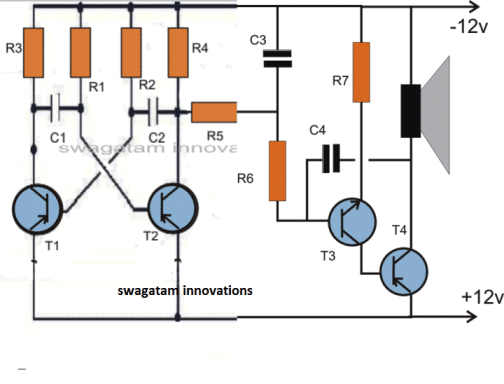
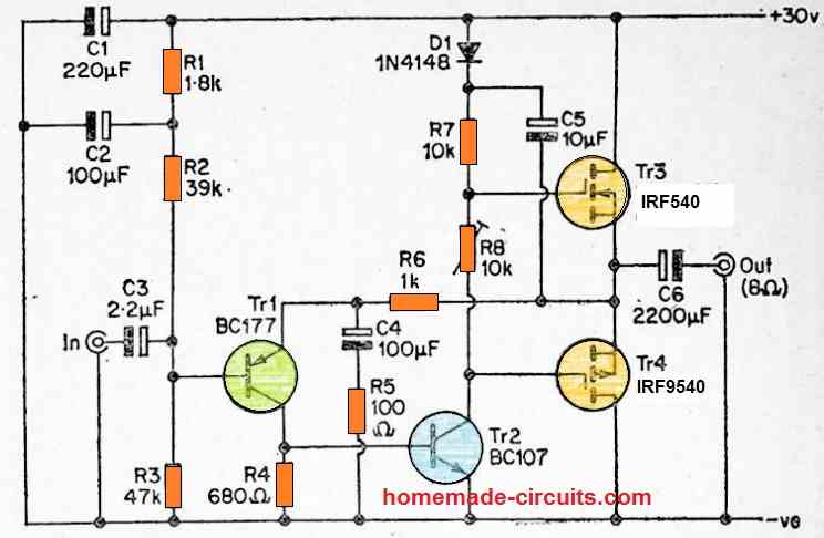
The circuit consists of two separate free running multivibrator and an oscillator.
A free running or astable multivibrator is one which has two quasi-stable states and the output of one stag is connected to the input of the other through a coupling capacitor.
Since both the states are quasi-stable, the output attained is continuously varying in nature i.e. high, low high low.
The output is in the form low pulses, the frequency of which depends on the base biasing resistor and the coupling capacitor.
When these resistances and condensers for both the stages are of different values, the output wave form is rectangular; this is because the time constant of the two quasi-stable states becomes different.
If this time constant of the two, states is made the same, the output obtained then is square wave. Two states of the multivibrator are made identical by the use of the same values of components.
The components used in this dual tone siren circuit result in a square wave output and the time constant selected is so as to give a fairly good rise and fall of the siren.
However, one may change the value of coupling capacitors to get any other desired time constant.
The second unit is an oscillator section. The condenser connected at the output is the feed back condenser. It determines the tone of the siren.
Higher the value of the condenser the lower is the pitch, for high pitch sound (generally used in siren) feed-back condenser ranging from 0.047 ufd to 0.1 mfd should be selected.
The speaker may be metallic case (horn type) or small paper cone. The metallic cone horn gives better results.
The transistor astable parts could be calculated with the following formula:
- T2 = OFF Period of transistor Q1 = ON Period of Transistor Q2 = 0.693 * R2 * C2
- T1 = OFF Period of transistor Q2 = ON Period of Transistor Q1 = 0.693 * R1 * C1
Component List (BOM)
| Component | Specification |
|---|---|
| Transistor (BC177) | BC177, 2 pieces (T1, T2) |
| Transistor (BC107) | BC107, 1 piece (T3) |
| Transistor (SK100) | SK100, 1 piece (T4) |
| Capacitor (0.1 µF) | 0.1 µF ceramic or polyester, 3 pieces (C1, C2, C4) |
| Capacitor (16 µF, 16V) | 16 µF, 16V electrolytic, 1 piece (C3) |
| Resistor (2.2K) | 2.2K Ohm, 1/4 watt, 2 pieces (R5, R6) |
| Resistor (22K) | 22K Ohm, 1/4 watt, 2 pieces (R1, R2) |
| Resistor (27K) | 27K Ohm, 1/4 watt, 2 pieces (R3, R4) |
| Resistor (10 Ohm) | 10 Ohm, 1/4 watt, 1 piece (R7) |
| Speaker | 8 Ohm to 16 Ohm, 1 piece |
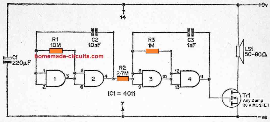
2 Tone Siren Using IC 7400
The next 2 tone siren circuit siren is built using two oscillators for generating the tones.
A third oscillator is incorporated to toggle its counterparts ON/OFF alternately, producing the required two tone sound effect.
You can try experimenting with the value of the capacitor for having different ranges of tones and change it as per your preferences.
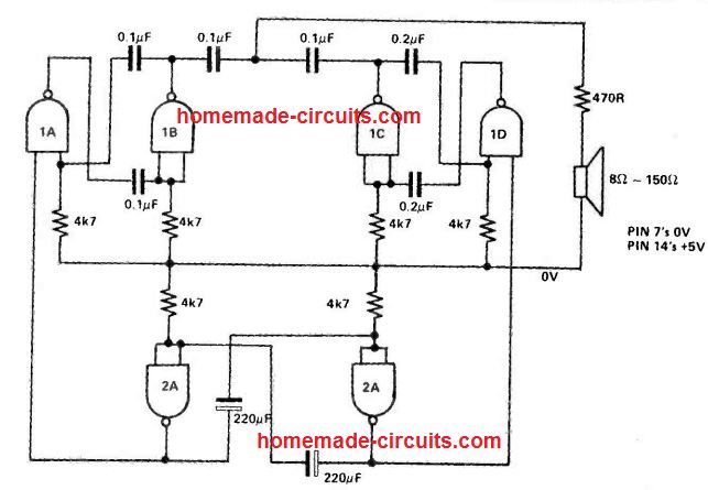
Formula for Calculating the NAND gate Oscillator
Frequency (f) ≈ 1 / (2.1 * R * C)
Where:
- R is the resistance in ohms
- C is the capacitance in farads
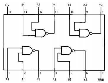
IC 7400 pinout diagram
Two Tone Alarm Circuit using NAND Gates
The frequency modulated alarm generator is yet another highly effective type of two tone alarm generator.
In this case, the frequency of the output tone is altered in a specific manner. By implementing a square wave modulating signal, for instance, the tone is altered between two different tones at a rate equivalent to the modulation oscillator's frequency.
When a triangle modulation signal is used, the output signal's tone is exponentially changed up and down with the operating frequency of the modulation oscillator.
However, R2 only weakly links the modulation astable's output to the tone generator astable's input, and the latter's operating frequency is switched up and down as the modulation oscillator's output shifts from one logic state to another.
As a result, the tone generator's frequency output is altered between roughly 500 Hertz and 1.2 kHz, and it simply does not work at its normal operational frequency.

Questions & Answers
Hi Abu,
I have gone through the link you have provided. I want to know, how did you connected the speaker. I can't find the speaker in the software. so, I connected a 8 ohm resistor instead. With this, I simulated the circuit. But, I am not getting the sound.
Hi Surya
I have simulated the circuit for you in LTSpice.
Here is the output:
https://dl.dropboxusercontent.com/u/20969135/dual-tone.wav
If you want the LTSpice data file, here it is too:
https://dl.dropboxusercontent.com/u/20969135/Two-tone%20Car%20Horn.asc
Hi Surya
I think you have read the article carefully. In the last para it is clearly mentioned that "feed-back condenser ranging from 0.047 uf to 0.1 mfd should be selected".
0.047µF = 47nF and 0.1µF = 100nF
With 0.1µF, the pitch of the sound would be low.
You could have googled for LT Spice to get the link. Anyway, here it is:
http://www.linear.com/designtools/software/
You will find the option for downloading for Windows 7, 8 and 10.
Hi Abu,
Thank you for simulating circuit for me. i have an doubt, in posted diagram c1 and c2 is .1uf but in your circuit c1 and c2 was 47nf . is there any problem using capacitor .1uf.
Can you send me a link for LT spice software to download.
Hi Swagatam
I tried the transistor as per the datasheet. But, it is not working. Can this circuit be simulated . If so, please provide me the link.
Swagatam, Thanks for your valuable reply. I tried as per reply and get back to you soon.
Surya, a transistor astable is one of the easiest circuits and has hardly any parts in it….please build the astable section again separately and keep testing it until it works….make sure the transistors are of good quality and are not faulty.
you can connect a small speaker in between the collector and positive of any one of the transistors, and test the sound with a 3V supply, if the speaker generates a buzzing sound then the astable may be working fine.
Hi Swagatam,
I tried this circuit but it is not working. I trace out this circuit and found the problem is multi vibrator circuit is not working. Only one transistor giving continuous output other transistor didn't give any output.
T1 Gives continuous output T2 didn't give any output. But T2 base getting 12 volt. Why it happens, any modification required in this circuit. Please do the needful.
Surya, you can easily verify the pinouts by checking the datasheet of the particular transistor, for example if it's BC557, then you can search for "BC557 datsheet" and confirm the pinouts there.
Hi Swagatam
Thanks for your reply.. How to check the transistor polarity? i google it some image show it as a 1st pin as Collector another image show it as 1st pin as Emitter. How can i confirm the transistor polarity? Please do the needful
Hi Surya, if your astable is not working then you will have to locate the fault by yourself, I cannot troubleshoot from here. you can check the transistor polarity or simply change them completely,
remember the supply here is opposite compared to the normal circuit diagrams, the positive is applied to the bottom rail and negative to the upper rail….you can disconnect R5 and first verify the astable working….and then proceed.
Hi Swagatam
I had discussed about a car horn circuit earlier, based on 2 x 555. I failed to locate that post. I tried that circuit, it produces sound which has digital signal and hence cannot be used in cars.
Is it possible to convert those digital signals into analog to have a real sound like electrical car horns? Any simple approach?
Hi Abu-Hafss,
You can conversation from your email, but again it could be quite tedious to find them from so many posts:(
the digital music should be fed to the "clock" input
Hi Swagatam
Yes, I will explained it through comments of some article. But I couldn't find the article.
Where the digital input be fed into the DAC circuit shown in the link you provided?
Hi Abu-Hafss,
A tried a lot too, but couldn't find it, I don't think a relevant article was published, we may have only discussed it through comments.
I do not have much idea regarding a DAC, rather an ADC is much easier.
may be this post could throw some light:
www(dot)circuitsgallery(dot)com/2012/04/digital-to-analog-converter-using-r-2r(dot)html