In this post I have explained how an accurate 10 LED tachometer circuit can be built using ordinary parts like IC 555 and IC LM3915. The idea was requested by Mr. Munsif.
What is a Tachometer
A tachometer is a device which is used for measuring vehicle engine RPM. Thus, it is basically used for checking the performance of the engine and helps an auto mechanic to understand the condition of the engine so that it can be corrected or optimized as per the desired specs.
Generally a tachometer may be considered an expensive equipment as these are highly accurate and intended for obtaining correct RPM rates of the concerned engine under test.
The conventional units are therefore very sophisticated and generate highly accurate results while testing.
However it doesn't mean that a simpler version cannot be built at home. With electronics at its best today, making a tachometer circuit at home isn't at all difficult. What's more the results obtained from such circuits are fairly accurate and provides the required data for assessing the overall working condition of the system.
The Design
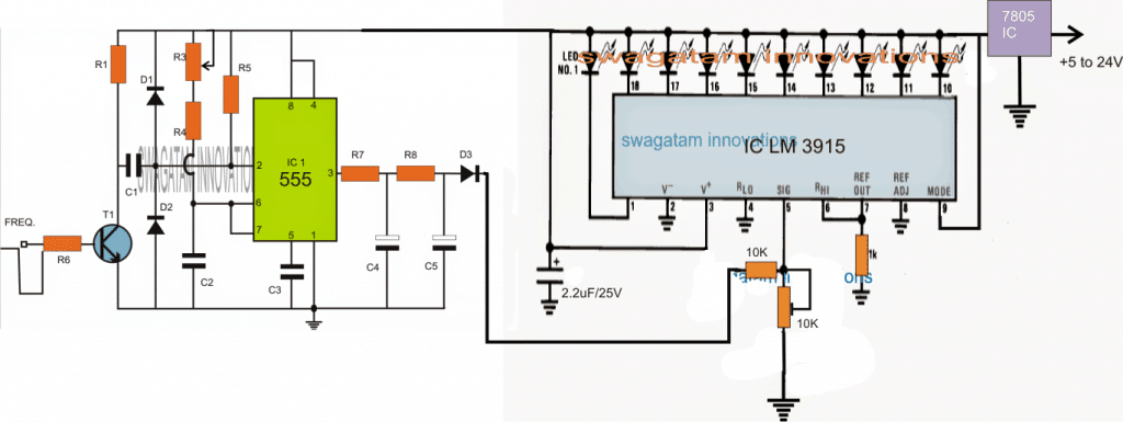
A simple 10 LED tachometer circuit can be seen in the above diagram.
The circuit basically consists of two mains stages. A monostable based tachometer using IC 555, and an LED driver stage using IC LM3915.
Referring to the figure below, the left side stage consists of a IC 555 monostable stage which triggers to the input frequencies from a given source such as an automobile engine, and causes its output to stay ON for a predetermined period as set by the R/C components at its pin6/2.
Circuit Diagram
This situation allows the user to set the response pattern of the output.
The output triggering of the IC 555 is further smoothened by an integrator stage using R7/R8 and C4/C5.
The integrated or smothened output is applied to a 10 step dot/bar LED driver LM3915 circuit stage.
The processed frequency to voltage conversion from the IC 555 tachometer circuit is appropriately displayed across the 10 LEDs associated with the LM3915 IC.
Since pin#9 of the IC is attached with the positive rail, the LED displays a bar mode pattern of the frequency level or the RPM level of the connected engine.
The 10 LED bar graph ascend or descend their illumination in response to the frequency levels from the automobile engine and allow the circuit to be used like an effective 10 LED tachometer.
Parts list for the IC 555 section
- R1 = 4K7
- R3 = CAN BE VARIABLE 100K POT
- R4 = 3K3,
- R5 = 10K,
- R6 = 470K,
- R7 = 1K,
- R8 = 10K,
- C1 = 1uF,
- C2 = 100n,
- C3 = 100n,
- C4 = 22uF/25V,
- C5 = 2.2uF/25V
- T1 = BC547
- IC1 = 555,
- D1, D2, D3 = 1N4148
Using only LM3915
A closer inspection of the above circuit reveals that the IC 555 stage is actually not required and seems like an overkill for the purpose.
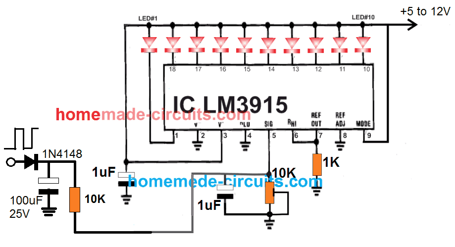
The main concept here is to convert the frequencies into an average DC whose level would be proportionate to the input frequency level. This implies that a simple diode, resistor, capacitor network would be enough to accomplish this action.
Also called an integrator, this small circuit network could be integrated with the LM3915 for ensuring that the voltage level stored in the capacitor is proportionately varied depending on the frequency levels.
Faster frequencies would allow the capacitor to charge and hold the DC proportionately better resulting in a higher average DC output and vice versa. This would in turn produce an equivalent level of LED illuminations on the LEDs attached with LM3915 output.
Here's the simplified version of the 10 LED tachometer using just a single IC M3915.
A Video Demo for the above Circuit can be witnessed below:
My Conclusion is not Correct
It's indeed very silly of me, since I completely missed the point that the above circuit was only interpreting the voltage generated by the motor, so it is not representing the frequency or the RPM, rather only the generated voltage levels.
Although this may be also proportionate to the RPM, it is technically NOT a tachometer circuit.
Therefore I confess that the first circuit shown using the IC 555 circuit the actual and true tachometer design.
Simple Tachometer Circuit
So far we studied a 10 LED version of a tachometer, however the idea could be much simplified using a moving coil meter as I have explained below. Here I have explained how to build a simple IC 555 based tachometer circuit which can be used for directly measuring any frequency over an analogue volt meter.
Circuit Operation
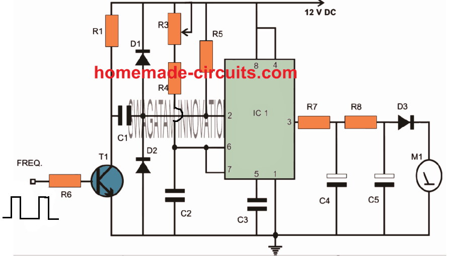
The circuit diagram shows a simple configuration utilizing the IC 555. The IC is basically configured as a monstable multivibrator.
The pulse is derived from the spark plug and fed to the end of R6.
The transistor responds to the pulses and conduct in accordance with triggers.
The transistor activates the monostable with every rising pulse of the input.
The monostable stays ON for a particular moment each time its triggered and generates an average ON time at the output which is directly proportional to the average trigger rate.
The capacitor and the resistor at the output of the IC integrate the result so that it can be directly read over a 10V FSD voltmeter.
The pot R3 should be adjusted such that the output generates the exact interpretations of the fed RPM rates.
The above setting up must be done with the help of a good conventional tachometer unit.
Parts List
R1 = 4K7
R2 = 47E
R3 = CAN BE VARIABLE 100K POT
R4 = 3K3,
R5 = 10K,
R6 = 470K,
R7 = 1K,
R8 = 10K,
R9 = 100K,
C1 = 1uF/25V,
C2 = 100nF,
C3 = 100n,
C4 = 33uF/25V,
T1 = BC547
IC1 = 555,
M1 = 10V FSD meter,
D1, D2 = 1N4148
Video Demo shows the testing of the above circuit
Simple Moving Coil Meter Tachometer Circuit
The figure below displays how a simple analog ,tachometer or revolutions per minute (rpm) meter can be built for motor vehicles. The circuit is driven by a regulated 8.2 volts acquired through the vehicle's 12 V battery and the ignition switch. The supply is stabilized using resistor R1, Zener diode D1, capacitor C1.
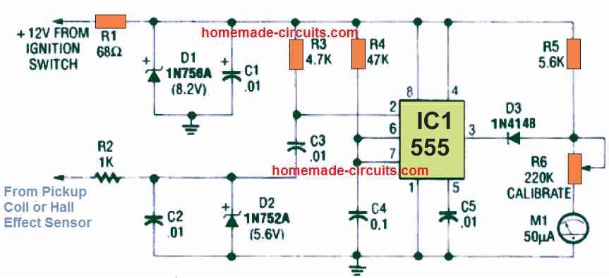
The 555 is activated with a signal from the vehicle's pickup coil processed by the circuit stage comprising of resistor R2, capacitor C2, and Zener diode D2.
The 50 uA moving coil meter M1, which is rigged as the the rpm indicator here, is triggered through pin 3 of the 555 via diode D3. The meter gets the driving current by means of a series-connected resistor R5 and potentiometer R6 through the power supply the moment the 555's output is high.
However, the current is decreased almost to zero by means of diode D1 as soon as the 555's output becomes low. The meter is actually a current indicating system, although it is hooked up like a voltage measuring meter with appropriate multiplying resistors.
FET Tachometer
The next diagram below exhibits a different analog tachometer meter which involves neither a multiplier resistor nor a stabilized power supply. In this design, the IC 555 output pin 3 is attached to the meter via JFET transistor Q1.
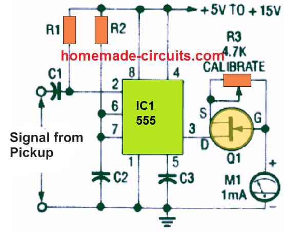
The FET is wired like a constant-current generator by means of potentiometer R3, it delivers a fixed-amplitude pulse to the meter irrespective of the fluctuations in the supply source.


Questions & Answers
How difficult to expand output from LED Bar Graphic to LED numeric output???
the above circuit cannot be modified for that, it will need a completely new design
So could you in theory change the frequency input to a magnetic pick up and have this work as an led speedometer?
yes that's possible, but the pickup output does not determine the vehicle speed, rather it's the wheel RPM which is normally considered for speed indications.
Right, but couldn't you add a variable resistor to the frequency input and calibrate the circuit so that for example: 1 led would light up when the wheel reaches 10mph (or the wheel rpm equivalent) or is there a simpler way to achieve the same result?
yes that's possible, I meant to say that speedometer is usually linked with the wheel for getting the right assessment of the RPM, the engine RPM could be accelerated even while the wheels are stationery.
Awesome. Thanks for the response and happy holidays 🙂
you are welcome!
Hi there
Where does the input come from and will this work on a single cylinder 2 stroke engine.
Cheers
Phil
Hi, the input comes from your bikes pickup coil, or from the spark plug.
reduce R6 to 10K if it is from the pickup coil
Hi
Thanks for the fast reply. Do I just wrap the wire around the HT lead.
Phil
yes that will do, also attach a 12V zener across base emitter of T1
sir more wisdom and knowledge in jesus name, can this work for my electric car if i tap the pwm from the motor controller to the above circiut
thanks abioye, yes you can do that….
sir can i use 22uf for c4 because i could not get 33uf thanks for your quick reply sir
yes that will do…
I don’t see the capacitance for C5 listed. If u used a 33uF in circuit lab to simulate there was no output, and I found an output of .5v – 4.5v for the estimated frequency range of my cars crank signal (66Hz idle, 755Hz rev limiter.) I still need to hook it to a function generator to test operation. I was just curious what your design calls for a value of C5?
The output RC network works like an integrator and makes sure that the output ripples are converted into a reasonably good exponentially rising and falling DC, which can be measured, or appropriately interpreted by the subsequent stages.
C5 can be a 4.7uF/25V cap.
also you can try increasing the value of C1 to 1uF, and adjust the R3 pot carefully for getting the right calibration at the output.
sir is it possible to change lm3915 to lm3914?
yes that’s possible!
I was concerned about the tach because of the price. I needed to measure the speed of my lathe at different speed settings. I added a small piece of the reflective tape to the drive shaft and the tach worked great. It measured the speed at each setting and was stable. The readings were able to be repeated the next day. This is a great product especially for the price
Best regards.
Thank you J. Laparaon for sharing your views, I am glad the design helped you and served the purpose. Please keep posting!
Where to connect FREQ and if i m using it on scooty India what is value of C5 . What is R3 pot means. Can it use for 110 cc engine. Thank you
Frequency inut can seen at the base of BC547. R3 pot can be used for optimizing the best possible response on the LED bar for the entire frequency range. You can use this circuit for any engine.
What is voltage of c1,c2,c3
disc caps are always rated at 50V or higher
Sir what is used on resistance on ic Lm 3915 leg 5 is confusing resistance has only 2 legs how to make that connection with other resistance. How 10k is connected in centre . Thank you
Rohit, that’s a preset as shown below:
short the center pin with any of the outer pins together, use this shorted pin to connect with the 10K resistor and pin#5, and then connect the other pin of the preset with the ground line.
Sir why R6 (resistance) is having two wire where to connect it .
R6 has a single end only, the other one is a square wave symbol…
make sure to make all the negative lines or the ground lines in common, otherwise the circuit will not work
Sir i can’t see a value of D3 and R2 and R9 are missing but listed in parts list where R2 and R9 will connect.
Rohit, R2 and R9 are not there, they were included for some other application, you can ignore them…D1, D2, D3 are all 1N4148
I am a auto electrician in sri lanka . I have found this circuit diagram when I am trying to find a circuit digram in internet to convert deisel pump rpm sensor signal to square wave puls .But I have changed my idea and I intend to make this circuit with led display to fit to the relavent car directly .Thank you for this unexpected help I got from your website .
Glad you found this circuit helpful, wish you all the best!
Hi Sir. Thanks for this project
As i want to use it to read rpm with a microcontroler… do you know to tell me if the output voltage is pwm ?
i have 2 options..
one is to use 2 resistors at the output as a voltage divider and read rpm with an analog input (but i want to use my analog inputs for other purposes)
and the second one if it is pwm output to use microcrocontrolers digital inputs for pwm
thanks in advance
Hi Caslor,
If you are using a microcontroller then the IC 555 circuit will not be required. You can directly feed the pulses from the hall effect sensor attached on the rotating shaft.
In the above design the output from the IC 555 will be a PPM not PWM, meaning it will be pulse position modulation. The position of the pulses will closer or wide apart depending on the RPM frequency.
Hi
Unfortunately my car is from 1970’s and the distributor doesn’t have any hall effect sensor.
i tried to use a single NPN transistor circuit to take pulses from the spark-plug cable but it was very noisy signal .
that is why i thought to use your circuit to get more cleared signal.
I will use an Arduino as a microcontroller and i saw that can read also PPM signals with interrupts
so maybe i can use your circuit with an additional 2 resistors at the output for voltage divider and drop the voltage to 5v max
In that case you can use the first circuit, just make sure to remove the resistor and capacitor network at the pin3 of the IC, and then you can connect your resistive divider.
Thanks again for the help
So i have to remove R7 & R8 , C4 & C5 .
what about D3 diode? should i remove it also or keep it ?
You can remove the diode also, it has no significance.
Hi i have a single cylinder motorcycle and i have arduino based circuit and it is working fine with signal from pick up coil but i want to connect it with sensor to make a meter to measure wireless rpm hand held device what kind of sensor you recommend and my arduino input is max 5v for frequency signal.
Hi, You can try infrared (IR) concept.
Apakah ini(skema no 1) bekerja di sepeda motor?
yes can be used in motorbikes or any vehicle.
Why are there 6 capacitors? In the component list only 5? And how much is the value of c4 c5? And at the input of LM3915 pin 3 there is a capacitor value of 2.2uf … and in the list C5 is 2.2uf too …
buenas tardes disculpa la señal de entrada al 555 es de la bobina o en el cable de bujia de alta tension gracias
Hi, It is from the pickup coil…
Hello! Tell me please, can I use second schematic, without 555, for a single cylinder motorcycle, and take signal from the hall sensor? ( crankshaft position sensor?) Or before inductance coil? Thank you!
Hello, yes that may be possible, you can try it.
Can i use a BC548 instead of a 546?
There’s no BC546 in the circuits
i mean 547
You can use BC548 in its place
What is the function of the IC7805 in your first diagram?
To provide a 5V stabilized DC to the circuit
Thank you! (I was confused as Vcc arrow is pointing away from the circuit)
No problem!
THANK YOU for this helpful and seemingly hard to find information.
My son has a little 250cc ATV and I’m trying to adapt an LED strip to brighten from 5V to 12V as the engine RPM revs (like a dimmer) for “underglow” that reacts. It’s nothing serious, just a fun project. I’m having a hard time understanding how I can wrap a wire around the spark plug wire to make something like this work. Would you be able to help or have ideas as to which circuit here would work best? Thank you so much!
Thank you and glad the information helped you!
I think winding across the spark plug may not be required….you can extract the voltage from the alternator, and connect the supply with the LED strip through a resistor and bridge rectifier. The resistor value may be selected such that it provides a dim light on the LED at 5V and higher illumination at 12 V
I have one question after successfully building the two circuits for a Yamaha race monster.
Led #1 is dimmely lit even when I disconnect the 555 oscilation circuit.
What do I need to adjust or replace to solve this?
I remember this being mentioned in an article, but can’t find it anymore. Once again thanks for the circuits!
Hope you can help
Glad you could make the design successfully.
I think all the LEDs from #1 to #10 can be completely shut off in the absence of an input signal by finely adjusting the 10K preset or by adjusting the 1K resistor value connected across pin6 and pin7.
Using the first circuit, can a MM5451BN (35 LED IC) replace the LM3915 (10 LED IC)?
And
Will the 555 still be needed or can the second circuit be used? (4 cyl engine with a tacho lead from ecu)
Or
will a new circuit need to be designed? Looked with Google to try and find one. Found 1 that uses a PIR chip, (where the 35 LED IC came from)
that means a lot more outlay for me just to create a trigger when the 555 will do it.
No, a MM5451BN (35 LED IC) cannot be used in place of the LM3915 (10 LED IC)?
The MM5451BN requires a serial data input from where will you supply that?
Ok, this might get messy. Might be a whole new project to place on your website.
Can you add another LM3915 IC to the circuit to make the total number of LEDS 20?
Can a fader circuit be add to the LEDS, so they fade out as the revs change?
Can a small add-on circuit be added to the second last LED to make all the LEDS in dot mode go to bar mode, to indicate nearly max revs?
This is for my car, a 4cyl with ecu plug for revs input.
(I am also building a dot LED battery monitor 10.5v to 15v)
That would require a lot of drawing. I am not sure if would be able to fulfill this requirement, let me see, in my free time I may try this.
how can i make only one led lit for that tacho? i mean if the 2nd led is “on”, the 1st led ” off”, if the 3rd led is “on” the 1st and 2nd “off’ anyone could help me? thank you
Keep pin#9 of LM3915 unconnected or disconnected.
very tqhank you, i’ll try this.
New problem, Pin 7 controls the brightness of the leds, how can the brightness be lowered when car headlights are turned on? as the lads are too bright at night. What needs to be added to pin 7 thru a resistor to earth? (guessing that’s where the circuit needs to be adjusted)
Looked at mosfets, transistors even adding a mini relay, but got complicated. Is there an easy add-on?
Pin#7 of which IC are you referring to? Sorry, I cannot understand your schematic.
LM3915, Pin 7 to earth (controls led brightness)
Changing the resistance dims the leds. Thats where I was trying to add something to lower brightness of the leds when car lights are turned on.
Actually I haven’t tried this current limiting feature so I cannot suggest about it. I checked the datasheet of the IC, there seems to be a formula for calculating the LED current using the pin#7 resistor. You can check the datasheet for the details. However, if you are able to reduce the LED brightness by simply changing the pin#7 resistor, then it is fine, you can do it.
Greetings for you all, Can you please tell me how to connect this circuit to the car ??
I’m trying to understand just on which wire i need to connect the input frequency
Thanks ????
Hi, You can integrate the signal from your pickup coil with the input of the second circuit. However before integrating please confirm the working of the circuit on your work bench, using an external frequency as the input signal.
Thanks a lot Sir, i will build the circuit 1st then try using external frequency source
But, I don’t know about this frequency source, is it a circuit to build or which set to use as a frequency source
You are welcome Ramy. The frequency generator can be built using a IC 555 astable or any other similar oscillator circuit.
Please build the first circuit because that is a real tachometer, the second circuit will not detect a frequency rather it will detect only the voltage fluctuations.
Great work and it has prompted me to think out side the box.
Can the circuit be altered to illuminate only a single LED at a time?
Also can it also be altered to include 20 or 30 LEDs for finer resolution (by a series of LM3915s ?)
What I have in mind is to have two tachometer circuits reading from two independent sources.
Then when both have the same reading use an AND gate arrangement to trigger an output.
Thank you
Thank you Paul,
Your ideas are all completely feasible.
You just have to keep the pin#9 of the IC disconnected to make the LEDs glow individually.
Cascading LM3915 ICs is also possible to get at least an output of 20 LEDs. The details can be found in the datasheet below.
Using an AND gate for processing two inputs also looks a viable idea.
https://www.homemade-circuits.com/lm3915-ic-datasheet-pinout-application-circuits/
good afternoon, do you still take requests? Is it possible to make a two column tachometer ? similar to an abacus. would you use 2 drivers and a 556 ic ?? I dont have the knowledge to make it restart to one after it calls the other driver . is that called a flashback ? , If you could think of something that would be great.
Hi, yes that’s possible by replicating the first circuit from the above article.
Sorry I am not sure about the “flashback” thing.
Two identical circuits can be used if the there are two input sources, if there’s only one input source then I think a cascaded circuit would be required.
Thank you so much for the drawing. I’ll test it to keep track of the basic speed of my generator.
No problem, all the best to you!
I was thinking about the tachometer that you sent a suggestion for. To be able to test the counter without the pickup. Should a 555 connected as an astable flip-flop with adjustable frequency be able to work. And trim it to the right frequency. I thought about measuring the rpm with an optical measuring instrument. Regards Göran
Sure, you can feed the astable pulses to the point where the pickup input is supposed to be connected in the tacho circuit.
I appreciate your commitment immensely with our questions, thank you very much. Göran
You are welcome, Goran!
Hi! Regarding the LM3914, it is possible to connect some outputs to make the LED shine longer than the other LEDs. Regards Göran
Yes, it is possible, connect the LED through a BJT in the following manner:
Take a BC557 BJT.
Connect its base with LM3914 output through a 10k resistor, followed by a series 1N4148 diode (anode to base, cathode to LM3914 output 10k resistor)
Connect LED between BC557 collector and ground through a 1k resistor.
Connect a 100uF capacitor between base and emitter of BC557..
Connect emitter of BC557 with the positive supply, preferably +5V.
It shows a point bar.
Did you connect pin#9 with the positive line, only then it will show bar graph, otherwise it will be dot mode…
Hello and thanks. I left pin 9 open because I wanted dots instead
ok, then what is the problem you are facing?
My question was. If I could connect several outputs, e.g. pin7-10, to make the LED shine longer than the others. because one output at a time goes low.
Yes, you can do that through diodes on each output (cathode to IC pinouts, and diode common anodes to the LED)
thoughts so much for info
You are welcome, let me know if you any further questions….
You are fantastic at helping people with electronics questions. I’m sure there will be more questions from you in the future
You are most welcome, please feel free to ask, i am always happy to help!
Hello again! Trying to explain how I think with the LEDs. With diodes 1N4148 on each output works well. Now to my problem. I have 3 diodes yellow. green. red. Yellow warns of low engine speed Green shows normal speed. Red warns of high speed. I would like to have the green diode within a much narrower range. Than the other diodes. Is it possible with this LM3914.
The outputs of the LM3914 correspond to a range between 0 and 200 mV at pin#5, so if you adjust the resistive divider across pin#5 so that your input voltage range corresponds to 0 to 220 mV at the resistive divider output, then it might fulfill your requirement.