A simple motorcycle battery over discharge protector circuit is explained in the following post. The circuit will prevent the battery from over-discharging by the motorcycle headlamp whenever the mo-bike alternator is not enabled or is idling in the neutral mode in which case the battery is normally subjected to excess loads via the headlamp bulb.
Increasing Motorcycle Battery Efficiency
Motorcycle batteries are normally a lot smaller with their sizes and ratings compared to the vehicle and the usage. The main use of the battery present in mo-bikes is for enabling electronic start through a press of the given start button.
However this small sized battery also has to undergo further stresses while operating excess loads such as the horn, the indicator lights, the tail light and the brake light.
Even though the above loads mostly tend to depend on the motorcycles battery power, these do not affect the battery charge level significantly.
The one that truly affects the battery is the motorcycle headlamp, which when switched ON starts drawing huge current via the alternator and the battery in a shared manner.
This is the reason why we normally see the headlight intensity vary with varying mo-bike speeds.
At higher speeds the alternator shares the load to fair extents, but in cases when the vehicle is not moving or is idling in the neutral mode, the lamp starts consuming substantial amount of battery power, depleting it's charge to dangerous lower levels, and this may happen within minutes if not switched OFF.
The proposed circuit of motorcycle headlamp low battery discharge protector circuit is intended exactly to tackle this issue automatically.
It's nothing complicated, it's a simple low battery cut-off circuit set to switch of the link between the battery and the headlamp whenever the battery level falls below some set predetermined level.
The circuit may be understood as follows:
How it Works
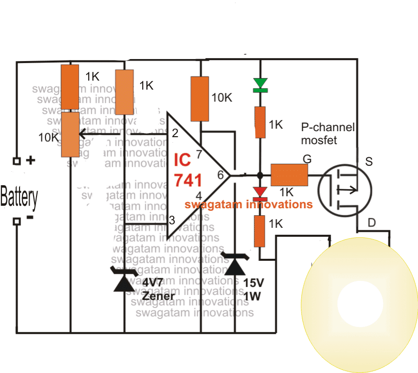
The opamp 741 IC is configured as a comparator here.
It's pin#3 is referenced at a fix voltage determined by the connected zener voltage. Pin#2 of the IC executes the function of the sensing input and keeps the output of the opamp pin#6 low as long as its potential stays above the reference value of pin#3.
The above condition is held in position as long as the battery voltage is above the set safe threshold level, which in turn keeps the output pin#6 at a low logic level.
The low at pin#6 ensures that the p-mosfet is allowed to conduct and illuminate the attached headlamp.
Therefore the headlamp is allowed to receive the required power through the mosfet as long as battery voltage continues to be above the safe threshold.
Now suppose the battery level begins falling beow the set level, this would mean pin#2 potential going down below the reference level at pin#3, or in other words pin#3 reference getting higher than pin#2 potential.
The above situation instantly prompts the output of the opamp pin#6 to pull at the supply level or at a high logic.
A high at pin#6 means the mosfet is now inhibited from conduction, switching off the headlamp.
The above situation continues in a flip flop manner until the battery voltage is no longer able to rise above the safe threshold when the lamp is permanently switched Off.
Circuit Diagram


Questions & Answers
Hi,
Is there a product to prevent prevent overcharging of a battery? I have a veteran motorcycle with a 3 brush 6V magdyno. The problem with these early three brush types is they supplied constant 6V, and with headlights off during the day it tended to overcharge the battery and ruin it after a while. It is described on ‘The Magneto Guys’ website in the three brush dyno information section, along with a solution that involves adding a resistor to the system. Unfortunately my headlight switch design doesn’t allow this type of fix. I was hoping to wire something to the battery that prevents overvoltage, through a resistor perhaps.
Thanks
You can attach the following simple design to your battery. The zener value must be selected in a such way that it is 1 V higher than the maximum charging voltage of the battery
Hello, I have one problem and I have been suffering with it for a long time, I can’t solve it. I would beg for help if it is not a problem.
It is about protecting the 12v car battery from deep discharge at 10-10.5v. I made some devices but the problem is that the device turns on and off because the battery voltage rises and the inverter turns on and then falls again and so on. Is it possible to make some protection that is activated with a voltage of 10v and cannot be turned on until the terminals are removed, or the main switch is turned off and on?
Hello, you can try the following transistorized version of a deep discharge protector and check if that helps!
Battery Deep Discharge Protection Circuit
Respected sir
Hope you will fine
Sir I want your help
Regarding bike electrical system
Old model bikes provide 2 phases 1will go to regulator rectifier and 1 will go to head light
I want to convert head light phase AC to DC
Please give me your suggestion how I’ll make proper circuit
I’ll try but I didn’t got results
Please help me
Your sincerely
Hello Mohammed, you can connect a series diode 6A4 with the phase line which goes to the headlight, and also connect a 2200uF/35V capacitor parallel to the headlight.
Thanks a lot sir
I’ll make the circuit and give you results
Thanks
Also I am interested to make CDI unite and regulator rectifier SO please help me
And how I’ll make ignition coil tester from 220v AC please suggest me thanks
No problem Mohammad, wish you all the best.
You can try the following concept for making the CDI tester
https://www.homemade-circuits.com/make-this-enhanced-capacitive-discharge/
Dear swagatam,
I seen circuit but how much input power and my battery is lithium battery it’s 60v 24ah nd 2nd battery is 72v 25ah how much power input voltage and how much output voltage to charging for battery , i m using dc to dc converter als , can u pls help me on it.
Hi Suman, are the 60 V and 72V full charge levels of the battery? If it is then it may require two different power supply sources, one rated at 60V 10 amp, and the other 72V 10 amp. These can be connected across the two changeover relays contacts separately. But first it is important to build the changeover circuit successfully.
Dear swagatam,
I have two dc to dc converter circuit I/P 12 -60v dc and O/P is 12-90v but for this i need auto changeover isolated switch circuit. For the same O/P voltage Battery to run hub motor
Hi Suman, what is the amp rating? The charging will be isolated via two relays, but I am not sure how two batteries with different ratings could be used for operating a single common load?
Dear swagatam,
Dc to dc converter booster out can giv 10-30ah and voltage is 12-92v , is it possible to make auto change over circuit can we use with preset 1battery and 2battery voltage settings
Dear Suman, you can use the last circuit from this article for the changeover, I think we have discussed this earlier also
https://www.homemade-circuits.com/automatic-dual-battery-charger-with/
Thnks swagatam,
Can u pls share the two different power supply circuit one for 60v and other for 70v.
Suman, You can build it using transformers and bridge rectifiers or through SMPS
Hola, gracias por tan buenos aportes tengo una inquietud: si yo conecto en paralelo al bombillo del faro un relé para controlar las luces de posición y que cuando se apague el bombillo se me enciendas estas luces es posible
Gracias por querer mis publicaciones, ¿podría mostrarme el esquema? sin diagrama puede ser difícil para mí sugerir. ¡puedes subir el esquema a cualquier sitio de imagen gratis y proporcionar el enlace aquí!
Hey sir
I have a street light led project that's going to use v 12v 4.5AH battery. Can i use the above circuit to prevent the led's from over discharging the battery when power is bot around,
What will i be required to change in order to make this circuit work under this conditions
Hi Joshua, yes definitely you can use the circuit for achieving the same….or you can also try the last circuit from this article:
https://www.homemade-circuits.com/2011/12/how-to-make-simple-low-battery-voltage.html
Hello Mr. Swagatam;
İ built this circuit but it doesn't cut the low voltage for battery? i used for 24V battery, could you kindly help please. when i try to adjust POT, both voltage at PIN2 and PIN3 are equal. what i mean is at PIN2 if i fix the voltage at 15 PIN3 also adjuting itself to 15. could you help please.
Hello oktay,
do the setting in the following manner.
apply an external 23V to the points where "battery" is printed.
connect a lamp at the shown points.
now adjust the preset until the lamp just switches OFF.
the circuit is set now, you can connect it in the application area.
but in actual use te mosfet will not cutoff the lamp, it will switch ON/OFF rapidly at the threshold point.
if you dont want this you can add a 100k resistor across pin6 and pin3
Hi, thanks for making this circuit, i like the explanation, which more usefull while creating this circuit, btw can we use a relay instead of P-channel mosfet? Its to hard to find here, since im living in small town 😀
I will try to do it as soon as i get time.
Can you make the circuit with relay driver?
Please 😀
you are welcome! Relay will keep on chattering at the threshold level, that's why I employed a mosfet here, you can try using transistors instead.
OK, a relay can be made to work by associating a delay network at the base of the driver transistor. This will control the chattering problem.
Replace the mosfet with an NPN transistor/relay driver stage and connect a 470uF/35V capacitor across the base/ground of the transistor.
Wire the relay N/O with the headlamp and battery positive.
In this case the pin#2 and pin#3 positions will need to be swapped, this is important.
The 10k and the zener at pin7 of the IC are not required actually, so they can be removed and pin7 directly connected with the positive.
Hi Swagatam,
The Batt. does not get fully charged when bike is in motion. and similarly I have a question regarding to Head lamp of non-Y2K slpendor, as I have one. The illumination of Headlamp is not so Bright, even I have changed the Headlamp Console to new, which has a Halogen Lamp fitting 12v/35w, but it has of no use, the lower filament light is still Dim…so regarding this can I connect Voltage Doubler Circuit at the rectifier ???
or how do I get Bright Light from Halogen same as all todays new bikes have.
Regards
You can see one example here:
i01.i.aliimg.com/photo/v0/332537589/Replacement_of_10W_halogen_lamp_SMD_LED.jpg
Hello pp,
you may have to replace the halogen module with the LED module inside the headlamp reflector.
The leds will need to be equipped with all the necessary current limiting circuitry before it can be powered.
Hi, PP
Did your motorbike headlamp using power from altenator which call fullwave rectifier? Or still halfwave? If your motorbike using halfwave rectifier then you must change to fullwave rectifier, this mean your motorbike headlamp now using power from battery, that will bright like new motors, and this circuit will help you (very usefull) for manage voltage battery 🙂
…OR LED Halogen lamps are available in market, Do you have any Idea ???
Hi swagatam,
I Need 1 help from you i have 2 lithium phosphate battery 60v 24ah nd 2nd is 60v 30ah, i need 1 circuit for self charging dual battery pack where one battery pack is used to run the hub motor while the other is charged need smart switching system where it monitors the voltage level of the batteries and decides which battery pack. Has to charge. pls help to share circuit and make video for this concept wiring diagram and circuit share me
Hi Suman, I think I have answered to this question in one of the other posts. You will have to first build and optimize one of the circuits explained in this article.
https://www.homemade-circuits.com/automatic-dual-battery-charger-with/
opamp or comparator circuits are very smart and will cut off the battery as soon as the set threshold is reached. But these are difficult to build and optimize for any new hobbyist.
I recommend the last since it can be built stage wise by verifying the two identical stages separately.
Dear swagatam,
The mention above circuit will work for the same 60v 24ah nd 30ah battery are any components can i change, i hve dc to dc converter booster 12-92v O/P with 30ah input will be 10-60v with 8-10ah . I want to use this dc converter .
Suman, the above circuit is over discharge protector, it will not protect against over charge.
Hello Sir,
By replacing Halogen lamp, Do you mean I should break halogen lamp and connect high wattage LED's after removing Upper and Lower Filament ???
Regards,
Hi PP,
Voltage doubler circuit won't work because here voltage is not the issue rather it's the low current which is causing lower illumination.
For better and consistent illumination, the only way of achieving it is to upgrade the battery to some higher level, meaning replace with a bigger battery.
In Place of halogen lamp you can try a LED lamp which would consume a lot less and produce equivalent lights.