Here we'll see how a simple yet accurate analogue speedometer circuit can be constructed at home using just a single IC and a few external passive components. The speedometer can be universally used with all 2-wheeler, 3-wheeler, even in bicycles for indicating their speeds.
Using Frequency to Voltage Converter
In my previous article I have explained about these wonderful ICs 2N2907/2N2917 which are basically frequency to voltage converters and therefore perfectly become suitable for all frequency measuring related applications.
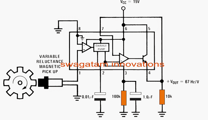
Referring to the simple speedometer circuit diagram below, we can see the IC LM2907 occupying the center stage in the configuration and forms the main detector device.
Circuit Operation
As can be see the internal of the IC comprises an input differential comparator, followed by a charge pump, an opamp buffer and a emitter follower amplifier stage.
Pin#1 of the IC becomes the tachometer input and accepts the magnetic pick up information in the form of varying magnetic electrical pulses.
The differential opamp compares the input with its ground referenced inverting input and amplifies even the minutest pulse detected at pin#1.
The function of the charge pump stage is to hold and pump the above amplified signals such that with increasing frequency the corresponding amplified output from the differential stage is sustained and boosted proportionately across the next opamp buffer stage.
This is achieved by the presence of the capacitors at pin#2 and the resistor at pin#3 of the IC.
The final proportional boosted potential is fed through the emitter follower transistor across the 10k resistor.
As given in the diagram, the output sensitivity here is around 1V for every 67Hz, meaning if the frequency reaches 67+67 = 134, would result a linear output of 2V and so forth.
Calculating the Output Voltage
To be more precise, the output voltage can be simply calculated using the formula:
VOUT = fIN × VCC × Rx × Cx,
where Rx is the resistor at pin#3 and Cx the capacitor at pin#2 of the IC.
This can be directly read by connecting an analogue moving coil voltmeter across the 10k resistor.
The magnetic pick-up for the proposed speedometer circuit could be made by winding 50 turns of 30SWG wire over a small ferrite ring.
The wheel should be complemented with an appropriately dimensioned magnet stuck or fixed over the rim such that the two elements come face to face once on every single rotation.
Circuit Diagram
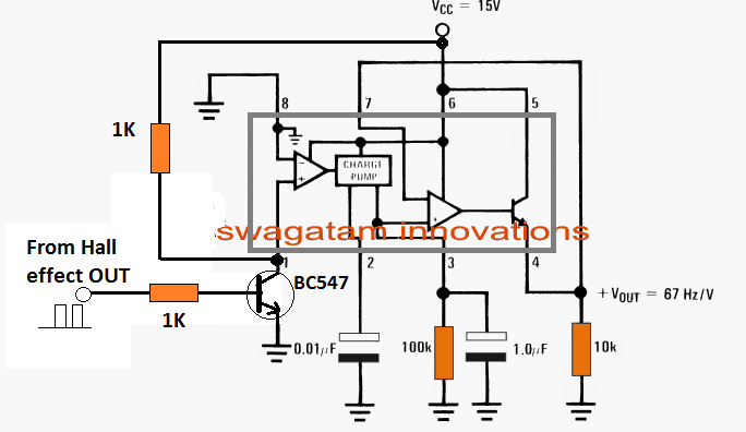
If a hall effect sensor is intended to be used as the sensor, then the pin1 of the IC can be modified with an external BJT stage as shown below, for the required frequency sensing.
For Hall Effect Sensor Integration


Questions & Answers
Could you explain what the BC547 does?
BC547 switch ON/OFF in response to the hall effect pulses, and creates the required frequency input for the IC
Thanks – my hall sensor is outputting a square wave 0V (off) and 5V (on). How does the BC547 modify that? Could you sketch what the output of the BC537 would look like?
When hall sensor outputs 5V, the BC547 conducts and grounds the IC sensing pin#1 sending a 0V signal to the IC. When the hall sensor outputs a 0V, the BC547 remains shut off, causing a 15V to enter the sensing pin#1 of the IC via 1K resistor. So basically the BC547 inverts the hall sensor signals and sends an equivalent ON/OFF pulse information to the IC.
Thanks. Afraid I don’t follow why one has to invert the signal from a 0V-5V square wave to a 15V-0V square wave? Would 5V not be enough?
5V will also work, but the transistor ensures perfect logic zero switching for the IC pin. Inverting the signal is not important or relevant. Direct connection with the hall effect might not produce perfect 0 volt switching for the IC opamp and might generate errors. However, to process a signal from the hall effect sensor a correctly calculated resistive divider would be required across the base/emmiter of the transistor, because the output from a hall effect never reaches a proper zero volt during the absence of a magnetic field
where i can put my hall effect sensor to read this analog values?
you mean near to running shaft ? or near to meter
Near the running wheel, and magnet stuck on the wheel, which must be face to face with the hall effect sensor when it approaches the hale effect sensor.
Hello,
I stumbled across this post and am wondering if you can help with a project I have. I am trying build a circuit to take a hall effect signal from a vehicle speed sensor, and adjust it so that the speedometer in my car will read correctly even though the wheel diameter is much larger than what the speedometer is calibrated for.
I have considered trying to use a frequency to voltage converter, adjust the voltage with a potentiometer, the convert the voltage back to a frequency. I cannot seem to find a VFC with good resolution down low. For example, at 60 mph the VSS signal is around only 70hz.
Thank you for your suggestions!
Hello,
I have a couple of VFC circuits in this blog which you can try and check if they work:
https://www.homemade-circuits.com/voltage-to-frequency-converter-circuit/
Digital gauges in motor vehicles usually have a diode labled “IGN” which has an internal earth and a outside contact.
As you know a car alternator “Ign” light operates differently to this. A circuit is needed to connect the two
existing wires, one from alternator and one from 12v ign power, to this LED.
Can you suggest a way to do this?
Sorry, I have no idea about these connections!
Very simply, the IGN light bulb is connected between the alternator (or generator in the old days…) + output and the battery via the ignition switch.
There is no ground connection as such.
When you switch on the IGN, the light sees +12 volts from the battery and a path to ground via the alternator (or generator) windings. So the light comes on.
When the car starts and the alternator starts charging, the light sees +12 volts (about) from the alternator so there’s no voltage difference across the bulb. It goes out.
The bulb is also used to provide a small current to the alternator, so if you replace it with an LED or even a bulb of the wrong wattage, the alternator may not work correctly.
Cars with an LED “battery” warning light will probably have a voltage sensing restistor instead of the incandescent bulb, and a circuit driving the LED.
Hell Mr Swagatam,
Congratulations on your excellent websites – you are certainly quite a prolific writer!
I’m about to get started building an electronic speedo for my elderly Suzuki. Speedo cable broken – that was easy to repair but it also destroyed the small speedometer gear box on the front wheel, which now costs over $100 to replace, if I can find one. My plan is to use your circuit design and take the output to a small DC motor to drive the speedo input, thereby keeping the original look, hopefully.
About Ian Simmons’ question:
1. The ignition terminal on OEM or commercially electronic instruments is usually to take a signal from the ignition switch when it is turned on. Power for the device may come from elsewhere, in which case the “IGN” signal tells the device when to be on or off, to avoid running down the battery.
2. The light referred to as IGN with regards to the alternator has really nothing to do with ignition. It is usually set up so that the light comes on when the engine is running or ignition is powered up, but there is no electrical output. It thereby indicates an alternator failure.
Best regards, Steve (Phnom Penh)
Thank you Mr. Steve, for your kind complements!
Yes you can try the above explained circuit, it will definitely work if all the connections are done correctly.
And thank you for explaining the ignition system of the car!
Hi Roger
Thank you for your reply and also thanks for sharing of your knowledge , very helpful and much appreciated! Also,I noticed that no one else posts their last name so is it possible for you to remove my last name from my article, please?
Thanks and have a nice day!
Gary
please, what is a charge pump? Thanks
Here, the charge pump refers to a circuit that produces an increasing DC level in response to the increasing input frequency, and ensures that the level does not drop during the OFF periods of the frequency.
How can I use this circuit with a 3 wire Hall Sensor with a 16 tooth trigger wheel mounted on my driveshaft for speedometer? I currently have a Megasquirt 2 Extra ECU (v3.0 board) that controls my fuel injection, spark control and knock control on my old Datsun. The ECU firmware doesn’t support a VSS signal for an electronic speedometer.
BTW, the tire size is 22.69 inch in diameter with a final gear ratio of 5.13. This works out to 888.85 tire revolutions per mile for 82.08 trigger wheel pulses per tire revolution (or 72957.20 pulses per mile) for a pulse frequency of 20.266 Hz.
Based on the equation VOUT = fIN × VCC × Rx × Cx,I should be able to select the appropriate Rx and Cx components to match the 20.266 Hz per volt.
Do you think this would work?
You can connect the 3 wire hall sensor by following its basic wiring layout. Connect its supply pins with 5V regulated suplly, and connect its OUT pin with the pin#1 of the IC.
https://www.homemade-circuits.com/linear-hall-effect-sensors-explained/
Thanks for confirming that a Hall sensor will work with this circuit.
BTW, in your example, how was the 67Hz per volt calculated?I
Thanks
Roger
It is calculated using the given formula, as suggested in the datasheet of the device.
By the way I have updated the hall effect integration diagram at the end of the post….
Thank you so much for pointing me in the correct direction. I never would have figured this out without your help.
Roger
Swagatam,
Can you please confirm as to what is the minimum Vcc allowed and the maximum Vout allowed on the LM2907?
Based on the data sheet Section 7.1 on the TI , it shows the supply voltage maximum at 28 volts but does not show any value for the minumum supply voltage. I understand that the supply voltage is the same as Vcc.
Roger, the recommended range is between 6 and 24V
It’s my pleasure!
Hello sir lm2917 Ic pin no 1 conecting to bike pickup coil
Mr.Singh,
yes, you can connect pin#1 it to the pick coil output
Hi Sir, i would like to as request if you can post about digital(7segment) speedometer for bike so i have idea or guide for personal use.
Hi Adem, I’ll try to do it soon, thank you! Basically, for this you will need a magnet and hall effect sensor on the bike’s wheel. The output can be then connected to the clock input of a IC 4033 seven segment display circuit.