In this post I have explained many simple NiCd charger circuits with an automatic overcharge protection and a constant current charging.
When it comes to correctly charging a Nickel-Cadmium cell, it is strictly recommended that the charging process is halted or cut off as soon as it reaches the full charge level. Not following this may adversely affect the working life of the cell, reducing its backup efficiency significantly.
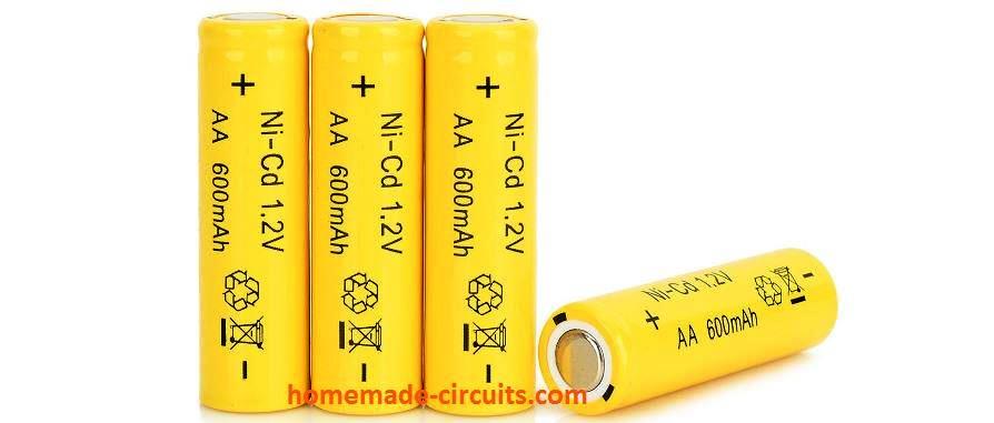
Simple Adjustable Nickel Cadmium Battery Charge
Practically every single nickel-cadmium battery in use today could be charged using the following universal adjustable Ni-Cad battery charger circuit.
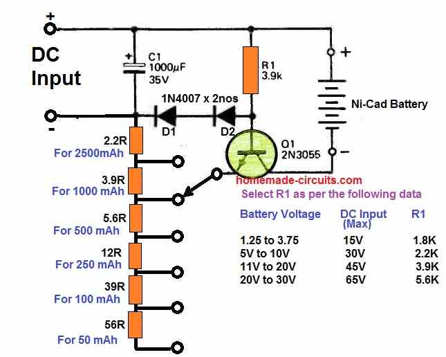
For batteries with a capacity ranging from 50 mA/h to 2500 mA/h, the rate at which they are charged can be adjusted through a rotary switch.
It promptly adapts to any battery voltage up to 20 volts. Voltage selection is not necessary. A fully depleted battery takes around 14 hours to charge, whereas a half drained battery takes correspondingly fewer hours to charge.
Nickel-cadmium batteries may be overcharged at the right ampere/hour rate without suffering any harm.
Since no damage will result from leaving the device on charge for 48 hours, a prolonged charging using a 10% ampere/hour charging rate has been adopted.
Using IC 4093
The next simple Ni-Cad charger circuit presented below effectively tackles the overcharging criterion by including facilities like a constant current charging as well as cutting off the supply when the cell terminal reaches the full charge value.
Main Features and Advantages
- Automatic cut off at full charge level
- Constant current throughout the charging.
- LED indication for full charge cut off.
- Allows the user to add more stages for charging up to 10 NiCd cells simultaneously.
Circuit Diagram
How it Works
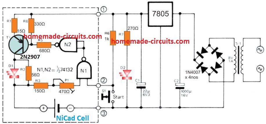
The simple configuration detailed here is designed to charge a single 500 mAh 'AA' cell with the recommended charge rate of close to 50 mA, nonetheless it could conveniently be customized cheaply to charge several cells together by repeating the area shown in dotted lines.
Supply voltage for the circuit is acquired from a transformer, bridge rectifier and 5 V IC regulator.
The cell is charged with a T1 transistor which is configured like a constant current source.
T1 on the other hand is controlled by a voltage comparator using a TTL Schmitt trigger N1. During the time the cell charges the terminal voltage of the cell is held at around 1.25 V.
This level appears to be lower than the positive trigger threshold of N1, which keeps the output of N1 high, and the output of N2 becomes low, enabling T1 to get the base bias voltage through the potential divider R4/R5.
As long as the Ni-Cd cell gets charged the LED D1 remains illuminated. As soon as the cell gets close to the full charge status its terminal voltage climbs to approximately 1.45 V. Due to this, the positive trigger threshold of N1 rises causing the output of N2 to go high.
This situation instantly turns off T1. The cell now stops charging and also the LED D1 is shut off.
Since the positive activation limit of N1 is approximately 1.7 V and it is controlled by a specific tolerance, R3 and P1 are incorporated to alter it to 1.45 V. The negative trigger limit of the Schmitt trigger is around 0.9 V, which happens to be lower than the terminal voltage of even a completely discharged cell.
This implies that connecting a discharged cell in circuit will never trigger the charging to initiate automatically. For this reason a start button S1 is included which, when pressed, takes the input of NI low.
To charge more number of cells the portion of the circuit revealed in the dotted box may be repeated separately, one for each battery.
This ensures that, regardless of the discharge levels of the cells, each one of them is individually charged to the correct level.
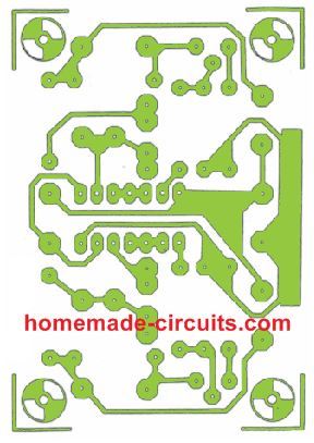
PCB Design and Component Overlay
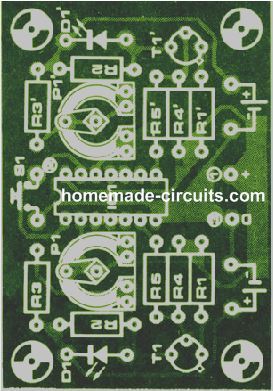
In the PCB design below two stages are duplicated for enabling two Nicad cells to be charged simultaneously from a single board set up.
Ni-Cad Charger using a Resistor
This particular simple charger could be constructed with parts that could be seen in just about any constructor's junk container. For optimum life (number of charging cycles) Ni-Cad batteries must be charged with a relatively constant current.
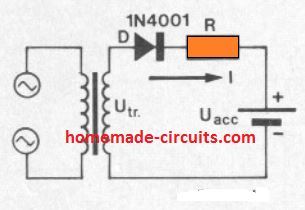
This is often accomplished rather easily by charging via a resistor from a supply voltage many times higher than the battery voltage. Change in the battery voltage as it charges will likely then have minimal influence on the charge current. The proposed circuit is made up just a transformer, diode rectifier and series resistor as indicated in figure 1.
The associated graphical image facilitates the necessary series resistor value to be determined.
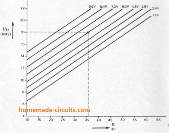
A horizontal line is drawn through the transformer voltage on the vertical axis until it crosses the specified battery voltage line. Then, a line pulled vertically down from this point to meet the horizontal axis subsequently provides us the necessary resistor value in ohms.
For instance, the dotted line demonstrates that if the transformer voltage is 18 V and the Ni-Cd battery to be charged is 6 V, then the resistance value will be around 36 ohms for the intended current control.
This indicated resistance is calculated to deliver 120 mA, while for some other charging current rates the resistor value will need to be reduced down appropriately, e.g. 18 ohms for 240 mA, 72 ohms for 60 mA etc. D1.
NiCad Charger Circuit using Auto Current Control
Nickel-cadmium batteries generally require a constant current charging. The below shown NiCad charger circuit is developed to supply either 50mA to four 1.25V cells (type AA), or 250mA to four 1.25V cells (type C) connected in series, eventhough it could simply be modified for various other charging values.
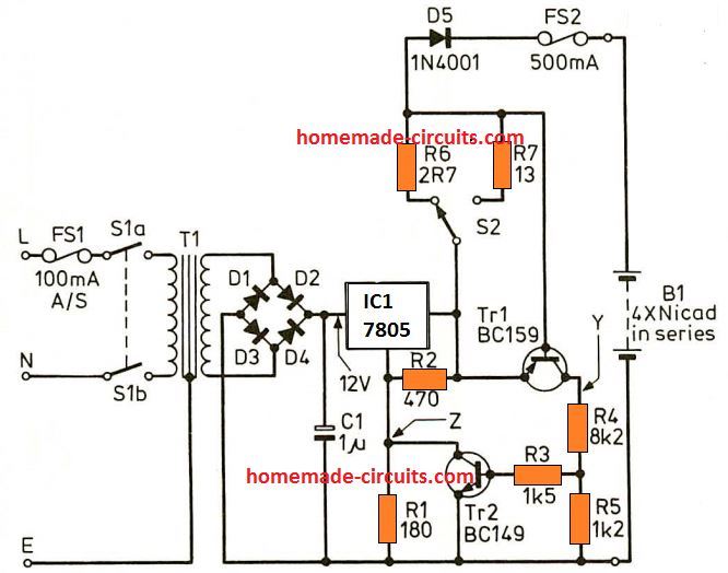
In the discussed NiCad charger circuit R1 and R2 fix the off-load output voltage to approximately 8V.
The output current travels by means of either R6 or R7, and as it rises transistor Tr1 is gradually switched on.
This causes point Y to increase, switching on transistor Tr2 and enabling point Z to become less an less positive.
The process consequently decreases the output voltage and has a tendency to bring down the current. A balance level is ultimately attained which is determined by the value of R6 and R7.
Diode D5 inhibits the battery which is being charged, providing supply to the IC1 output in case of the 12V is removed, which could otherwise cause serious damage to the IC.
FS2 is incorporated to protect against damage to the batteries which are under charge.
Choice of R6 and R7 is done through some trial and error, which means you will need an ammeter having a suitable range, or, if R6 and R7 values are genuinely known, then the voltage drop across them could be calculated through Ohm's Law.
Ni-Cd Charger using a Single Op Amp
This Ni-Cd charger circuit is designed for charging standard AA size NiCad batteries. A special charger is mostly recommended for NiCad cells for the reason that they possess an extremely low internal resistance, resulting in an increased charging current even if the utilized voltage is just slightly higher.
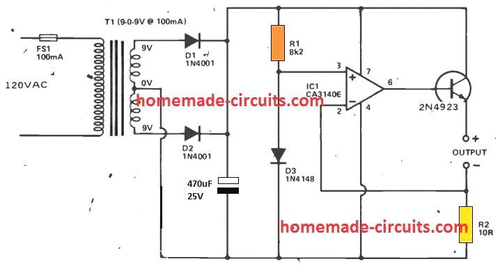
The charger should therefore include a circuit to restrict the charge current to a correct limit. In this circuit, T1, D1, D2, and C1 work like a traditional step-down, isolation, full-wave rectifier, and DC filtering circuit. The additional parts offer the current regulation.
IC1 is employed like a comparator with a separate buffer stage Q1 providing a appositely high output current functionality in this design. IC1's non-inverting input is supplied with a 0.65 V: reference voltage presented through R1 and D3. The inverting input is connected to ground through R2 within quiescent current levels, allowing the output to get completely positive. Having a NiCad cell attached across the output, a high current may make an effort to via R2, causing an equivalent amount of voltage to develop across R2.
It might merely increase to 0.6V, nevertheless, an increasing voltage at this point reverses the input potentials of the IC1 inputs, causing the output voltage to be reduced, and lowering the voltage around R2 back 0.65 V. The highest output current (and also the charge current received) is as a result the current generated with 0.65 V across 10 ohms, or 65 mA put simply.
Most AA NiCad cells possess a optimum preferred charge current of no more than 45 or 50 mA, and for this category R2 must be increased to 13 ohms so that you can have the appropriate charge current.
A few rapid charger varieties may work with 150 mA, and this demands lowering R2 to 4.3 ohms (3.3 ohms plus 1 ohm in series in case a ideal part cannot be procured).
Furthermore, T1 needs to be improved to a variant with a current rating of 250 mA., and Q1 must be installed using a tiny bolt-on finned heatsink. The device can easily charge up to four cells (6 cells when T1 is upgraded to a 12 V type), and all these should be attached in series over the output, and not in parallel.
Universal NiCad Charger Circuit
Figure 1 exhibits the full circuit diagram of the universal NiCad charger. A current source is developed using the transistors T1, T2 and T3, that offer a constant charging current.
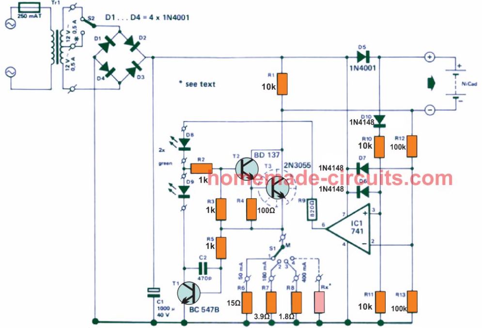
The current source becomes active only when the NiCad cells are attached the correct way round. ICI is positioned to check the network by verifying the voltage polarity across the output terminals. If the cells are rigged properly, pin 2 of IC1 is not able to turn as positive as on pin 3.
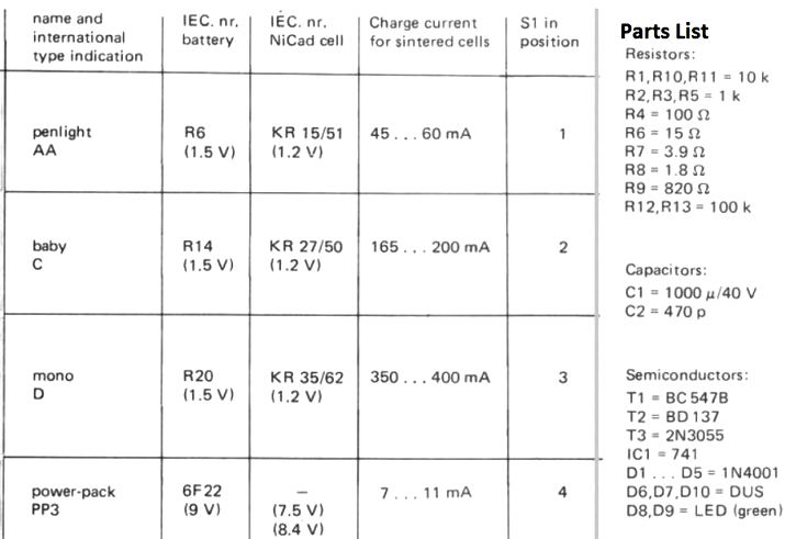
As a result IC1 output gets positive and resources a base current to T2, which turns on the current source. The current source limit could be fixed using S1. A current of 50 mA, 180 mA and 400 mA could be preset once the values of R6,R7 and RB are determined. Putting S1 at point 1 shows that the NiCad cells can be charged, position 2 is intended for C cells and position 3 is reserved of D cells.
Miscellaneous Parts
TR1 = transformer 2 x 12 V/0.5 A
S1 = 3 position switch
S2 = 2 position switch
The current source works using a very basic principle. The circuit is wired like a current feedback network. Imagine S1 to be at position 1 and IC1 output is positive. T2 and 13 now begin getting a base current and initiate conduction. The current via these transistors constitutes a voltage around R6, which triggers T1 into operation.
An escalating current around R6 signifies that T1 can conduct with greater strength thus minimizing the base drive current for transistors T2 and T3.
The second transistor can at this point conduct less and the initial current rise is restricted. A reasonably constant current by means of R3 and the attached NiCad cells thus gets implemented.
A couple of LED's attached to the current source indicate the operational status the NiCad charger at any instant. IC1 resources a positive voltage once the NiCad cells are hooked up in the right way illuminating the LED D8.
If the cells are not connected with correct polarity, the positive potential at pin 2 of IC1 will be higher than pin 3, causing the op amp comparator output to become 0 V.
In this situation the current source will remain switched off and LED D8 will not illuminate. An identical condition can transpire in case no cells are connected for charging. This may happen because pin 2 will possess an increased voltage compared to pin 3, due to the voltage drop across D10.
The charger will only activate when a cell comprising of a minimum of 1 V is joined. LED D9 shows that the current source is operating like a current source.
This might appear quite peculiar, however an input current generated by IC1 just isn't adequate, the voltage level also needs to be large enough to reinforce the current.
This implies that the supply should always be greater than the voltage across the NiCad cells. Only in this situation the potential difference will be sufficient for the current feedback T1 to kick-in, illuminating the LED D9.
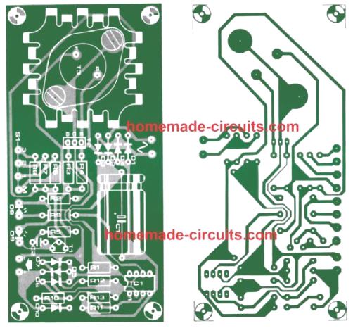
PCB Design
Using IC 7805
The circuit diagram below demonstrates an ideal charger circuit for a ni-cad cell.
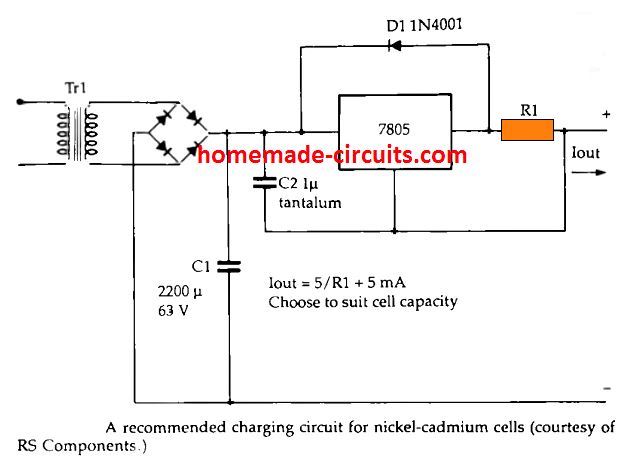
This employs a 7805 regulator IC to deliver a constant 5V across a resistor, which causes the current to be dependent on the value of resistor, instead of on the cell potential.
The value of the resistor should be adjusted with regard to the type that is used for charging; any value between 10 Ohm to 470 Ohm could be used depending on the cell mAh rating. Due to the floating nature of the IC 7805 with respect to the ground potential, this design could be applied for charging individual Nicad cells or series of a few cells.
Using 7805 and LED based Constant Current
The next circuit is dependent on a voltage regulator 7805 which handles a fixed load R1, and a varying load in the form of two NiCd batteries. The outcome is quite noticeable: voltage and load both are constant. The complete device including the voltage regulator and load R1 could subsequently be hooked up in series to a varying potential load, which is in this particular case our nickel cadmium battery which is going to be charged, and we have the current remaining totally constant. This situation is, surely, always assuming that the input voltage is adequately high.
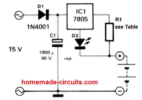
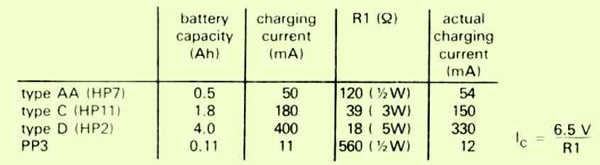
The circuit includes a small extra feature which is the LED connected in series with the ground pin of the regulator lC. This LED is configured to work like a NiCd charging indicator.
A predetermined current of 8mA +/-1 mA, that is determined by the preferred output current and which should be incorporated to this output current, runs by means of the LED. While fixing the value of the resistor R1, it is crucial to rememeber about the extra 1.5 V dropped across the LED.
As already considered, this current source is utilized as the charging current for NiCad batteries. As opposed to lead-acid batteries NiCd batteries must be charged with a constant current.
Typical NiCads needs to be charged with a current that must be 1/10th value of its mAH rating, and charged for a approximate duration of 14 hours.
It is always recommended to ensure that the NiCd cell is fully always discharged, and then quickly connected to a charger. This will enable the cell to have a longer life and provide higher number of charge/discharge cycles.
Charging Ni-Cd Cell from a 12V Supply
The most fundamental principle for a battery charger is that its charging voltage must be more than the nominal battery voltage. For example, a 12 V battery should be charged from a 14 V source.
In this 12V Ni-Cd charger circuit, a voltage doubler based on the popular 555 IC is used. Because output 3 of the chip is connected alternately between the +12 V supply voltage and earth, the IC oscillates.
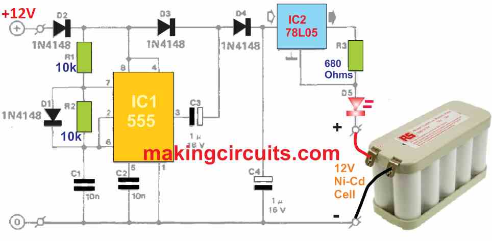
C3 gets charged through D2 and D3 to almost 12 V when pin 3 is a logic low. The moment pin 3 is logic high, the junction voltage of C3 and D3 boosts to 24 V due to the negative terminal of C3 which is plugged at +12 V, and the capacitor itself holds a charge of the same value. Then, diode D3 becomes reverse biased, but D4 conducts just enough for C4 to get charged over 20 V. This is more than enough voltage for our circuit.
The 78L05 in the IC2 positions acts as a current supplier which happens to hold its output voltage, Un, from appearing across R3 at 5 V. The output current, In, can be simply calculated from the equation:
Iη = Uη / R3 = 5 / 680 = 7.4 mA
The properties of the 78L05 include drawing current itself as the central terminal (usually earthed) gives ours around 3 mA.
The total load current is about 10 mA and that is a good value for constantly charging NiCd batteries. To display that charging current is flowing, an LED is included in the circuit.
Charging Current Graph
Figure 2 depicts the properties of the charging current against battery voltage. It is quite evident that the circuit is not entirely perfect as the 12 V battery will be charged with a current measuring only around 5 mA. A few reasons for this:
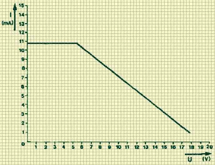
- The circuit’s output voltage seems to drop with the escalating current.
- The voltage drop across the 78L05 is around 5 V. But, an additional 2.5 V must be included to ensure the IC operates precisely.
- Across the LED, there is most likely a 1.5 V voltage drop.
Considering all the above, a 12 V NiCd battery with a rated capacity of 500 mAh could be charged uninterruptedly using a current of 5 mA. In total, it is only 1% of its capacity.
Charging 8 Cells in Series with Auto Cut off
With a constant current of up to 100 mA, this circuit can charge up to eight 1.25 V Nicad batteries. The charger trips and charging stops when the battery voltage reaches a predefined threshold. The voltage of a Nicad cell rises as it is charged, reaching a maximum of about 1.45 V when completely charged.
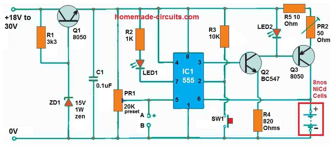
When the voltage of an eight-cell battery reaches 11.6 V, it is completely charged. A Nicad cell's suggested charging current is generally 10% of its mAh rating, or 50 mA for a 500 mAh battery. Connect a voltmeter to terminals A and B to complete the circuit. PR1 is set to the appropriate trip voltage, which in this case is 11V6 for eight batteries.
Then, between terminals C and D, a milliampere is attached. The minimum charging current is adjusted by PR2 when the reset button SW1 is briefly pushed. Between terminals C and D, the battery could now be attached. LED 2 illuminates as soon as SW1 is pushed, indicating that the battery is charging.
The charging current reduces to zero when the battery voltage reaches the predefined trip voltage, and LED 1 illuminates, showing that the battery is completely charged.




Questions & Answers
Iwent through the article above and appreciate the way of explaining. I shall thank you to give a circuit for charging 3.6VDC / 4500mAh NI-CD battery with autocut facility. I have some of such type of batteries but do not have a good circuit for charging. Already I lost a few batteries due to wrong way of charging. Please help. Thank you,
Thank you! You can try one of the circuits explained in the following article:
https://www.homemade-circuits.com/usb-automatic-li-ion-battery-charger/
Just make sure that your input supply is rated with a current not more than 500 mA.
You can use a transformer power supply of 6 V 500mA as the input supply.
Thank you very much for a prompt action to reply me with a solution. In fact this is a great help to me. I will follow your publications when ever I need. Thank you.
You are most welcome, I am glad to help you!
Please I need a circuit diagram to charge 18 pieces of 1.5V nicd batteries within 2 hour with auto cutoff at full charge. Thanks
You can try the circuit explained under the heading: “Ni-Cd Charger using a Single Op Amp”
You can put all the cell in parallel and dimension the R2 value appropriately.
sir,
I need 17 pcs ni cad battery charger
Hi Masum, sorry I don’t sell ready made kits from this website.
Dear Sir Swagatam
Help. I hope you are fine and healthy
I was looking for a circuit in my notebooks when I found the circuit diagram of a flashlight which I had given it as a gift to a friend of mine a few years ago. I remember that the flashlight was made in Germany and had worked me well for long years. It needed 2 Nos. of 1.2 v NiCd batteries and it took about 15 hours till the batteries got fully charged. you know better the role of capacitors in transformerless circuits is very important and great care should be taken to choose from a good quality such as one that I will send pictures of it through your Email along with the picture of the aforementioned circuit diagram. Perhaps it would be useful for your readers.
Best regards
Ersa
I hope you like it.
List of components:
R1 = 1R5 1/4W
R2 = 220k 1/4W
R3 = 270k 1/4w
C1 = 470nf 400v
D1 = LED red
D2 to D5 = 1N4007
Bat. = 2.4V 700mAh = 2×1.2V
Lamp = 2.5v 300mA
Thank you so much Dear Ersa.
It is indeed very useful circuit and the readers will be very happy to learn about the concept.
I have published the details at the end of the following post:
https://www.homemade-circuits.com/how-to-make-led-flashlight-circuit/
Dear Sir Swagatam
Hello. Once again you published my circuit diagram. I am so happy you found it useful for readers. Thank you very much for encouraging me.
God bless you
With best wishes
Ersa
Please ignore my previous comment for errors.
Thank you so much Dear Ersa,
Your kind contributions are much appreciated. Please keep up the good work
All the best to you. God bless you too!
Hello Swagatam,
I am building a 24v Nicd battery pack with many cells in a parallel+series configuration so I need to know the best way to charge this pack and if you have any circuits that could help?
Nominal capacity of the pack will be about 70Ah.
Should I charge the pack as a whole or charge each parallel bank to 1.5v?
Many thanks,
Kyle
Hello Kyle,
I think charging each parallel bank with 1.5V would be a convenient way to charge the cells. However to implement this you would require a current controller installed individually for each cell. This could be in the form of a high watt resistor which should allow a current not more than 1/10th of the cell mAh.
If you think this is too much work, then you can connect many cells in series and use a common high watt current limiting resistor for this series combination. This method could be sometimes inefficient but much easier than charging the cells in parallel with a current controller for each cell.
Hello Swagatam,
Okay so I was thinking correctly then!
The trouble is not giving 1.5v, but giving 1.5v at a high current and watching for the small voltage drop to signal the cell is full….
My estimation is looking like 16 cells in parallel. The battery pack will be a 20S16P configuration.
Could I simply use a LMxxx IC for charging these cells? Or will this lead to damage over time?
Many thanks again,
Kyle
Hello Kyle,
You can use LM317 or LM338 IC for generating the 1.5 V high current, but you will have to install a high watt resistor for each individual cell. Each resistor value should be such that it allows a current that’s 10% of the cell’s mAh rating. So you will need 16 resistors one for each cell. If the mAh of each cell is 1000 mAh then the resistor must be calculated to allow only 100 ma current and so on.
Hello Swagatam,
Yes that makes sense, but what about detecting the small voltage drop at the end of the charge? Won’t a constant charge eventually overcharge and damage the cells?
Or maybe because of the many cells in parallel, it is not possible to detect the end of voltage drop?
Thanks again,
Kyle
Hello Kyle,
You can keep the charging voltage marginally lower than the actual full charge level of the battery, which will ensure that the batteries can never get over charged. For example if the actual full charge level of the battery is 1.5V, then you can make the input voltage set at 1.48V. Although this will mean that the batteries are getting only 90% charged, they can never get over charged.
Hello Swagatam,
Ahh okay that makes sense!
What if I were to put a resistor and diode at the positive end of each 20S series string, and connected them all to a charger in parallel?
Would the diode prevent each string from discharging into each other and the resistor would limit the current to C/10?
Many thanks again!
Kyle
Hello kyle,
charging in series may not be a good idea since the charging could be then inconsistent across the cells. You will have to connect them in parallel and then charge with individual resistors.
Yes a diode can be added in series with each cell to avoid cross discharge of the cells. But remember each diode will drop 0.6V, so this much voltage much be raised to compensate the correct charging value for the cells.
Hello Swagatam,
Okay charging the parallel banks to 1.48v sounds like the best idea, but the only issue I see is bypassing the resistors for discharging and how to prevent parallel cells from discharging into another cell if they are in the same parallel pack?
Thanks again Swagatam,
Kyle
Hello Kyle,
You can add diodes in the following manner to prevent cross discharging and for bypassing the resistors while discharging…. but the problem is that the diodes can drop 0.6V which can be huge when compared to 1.5V rating of the cells:
Hi Swagatam,
Can this circuit be used to charge a 9V battery, NiCD?
Best Regards,
Nélio
Hi Nelio,
yes the second circuit can be used for charging a 9V battery. The formula for the resistor will be:
R = (Supply DC – 9) / 0.05
My previous comment was to build a 3.6 volt battery charger with a circuit board.
Hi Swagatam,
I am an electronics hoppyist and a fan of yours. I am trying to build a circuit board to charge 3 three AA NiCD batteries. The batteries supply power to 8 to 10 5mm 3 volt LED lights through the same circuit board. The input is from a water wheel supplying between 5 and 13 volts. I currently have the input going to a voltage regulator so that I have a reasonably steady 5 to 8 volts input goint to the battery charger. Although not necessary, it would be nice to have an LED light to show charging and an LED light to show fully charged. I purchased a similar product from DiGi Key Electronics. Their part number is 1738-1227-ND. This is a 3.7 volt charger for lithium batteries. The concept is what I need but it only takes a 5 volt input and it is for lithium batteries – so it won’t work for me. Thanks for any help you could give me.
Hi Robert, thank you for liking this site! I Appreciate it!
You can probably try the following design to charge your battery and also get the required LED indications. The 2N2222 along with its base zener diode restrict the output voltage to the 3.7V Ni-Cd battery to around a fixed 4V. The current limiting resistor must be calculated so that it limits the current to the battery to 50 mA.
Dear Swagatam
Hello. would you please tell what is the function of Diode 1N4001 in circuit under the topic “Using IC 7805”
Thank a lot Sir
wish you all the best
Nassim
Dear Nassim, it is for protecting the IC 7805, in case the input side is accidentally shorted. In such situation the voltage from the battery can enter through the IC and damage it, the diode bypasses the IC and protects the IC in such conditions.
Dear instructor; Sir Swagatam
Hello. I thank you very much for answering my questions. You are kindly requested to please tell me:
1. What should we do to prevent IC7805 from output short circuit ?
2. Are we allowed to do so with all regulated power supplied 78.. series?
3. Since the input voltage of 78.. ICs is about 30V, the voltage after bridge rectifier won’t damage the 7805?
wish you all the best
affectionately yours
Nassim
Hello Nassim, the 7805 has an internal short circuit protection therefore even if the output side of the IC is shorted or overloaded that won’t cause any damage to the IC.
Yes the maximum voltage to 7805 must not exceed 30V preferably, so you will have to make sure that the input supply is rated at 30V
Dear Sir engineer Swagatam
Hello. I hope that you are fine and healthy. I have still one question. I want to know the amount of DC V after bridge rectifier which is certainly
not above 30V as you have mentioned .
Thank you in advance for your reply
Wish you smiling lips
Best regards
Nassim
Dear Sir Swagatam
Hello and thank you very much. I made a very bad mistake and thought that bridge diodes had been connected directly to 220V mains ???!!! thank you again for your kindness
I will never forget you great favor
Wish you all the best
Truly yours
Nassim
No problem Dear Nassim, wish you all the best!
Dear Nassim, the output voltage after the bridge rectifier will be = transformer secondary voltage x 1.41, so you will have to select the transformer accordingly.
I am wondering if I can carefully solder very fine wires to ni-cad batteries, for electric razor no longer available batteries. Thank you SIR. Respectfully, Bob.
Hello Bob, If the unit had NiCad batteries originally, then it may be possible to replace with NiCd batts having the same specs as the original
Swagtam,
I need to initially boost charge and then switch to trickle charge 12v NiCad packs; do you have a circuit which will do that? They are standard ‘Super C’ cells with a capacity of 1200mAh
Hello Paul, you can try the following circuit:
That is excellent, thank you Swagatam
My pleasure Paul!
Hi Swagatam,
I have a circuit that requires 12v supply. The circuit is a mouse and rodent deterrent. It is activated by a PIR and flashes 15 white LEDs using a 555 timer. When there is movement the circuit flashes for about 3 minutes. If there is more movement, it will repeat. It is in a location where I only have power when the lights are turned on, so I want to power the circuit with 8-1.2v AA NIMH batteries in series for 9.6v . I would like to design a circuit to automatically charge the battery pack with 12v supply when the lights are switched on and will not overcharge the batteries, but will not discharge the batteries when the lights are switched off. The location is not very accessible, so I want the circuit to be safe and not able to start a fire. I hope you have time to post such a circuit. Thanks!
Hi Norman, you can probably try applying the following concept:
The LED indicates low battery, at which the load will be almost cut-off
Sr. in section “Ni-Cd Charger using a Single Op Amp” you show an scheme circuit with is wrong connected. Electrolytic Capacitor will blow up, and O.P. will not work at all since it is not rightly power biased. Please consider revising.
Thanks Colo, for pointing out the mistake, I have now corrected and updated the diagram accordingly.
Thank you for your comprehensive information. I use a gas detector powered by six NiCad “D” cells. The charger for the device has a red and green LED. The green illuminates; the red does not. There is a circuit on the gas detector that lets me know when the batteries are charged, but I always am concerned about overcharging. I haven’t been able to find a 6-cell charger that I can adapt to my gas detector, allowing the batteries to be charged without opening the device and removing the batteries, so I am considering building one using your diagrams and instructions. My electronic knowledge is limited, but I can follow directions and use a soldering iron. Since the total voltage of the six cells in series is approximately 9 V, I presume I would build a charger for 9 V. What I am wondering is if the charger power rating is that of one D cell times 6. Can you comment?
Hi, I think you can take the help of the second concept shown in the above article. It is by far the easiest and the safest Ni-Cd charger that you can get. The associated graph provides all the details regarding the input supply, battery voltage and the resistor value for the current control.
Thank you for the reply. I shall follow your recommendations.
— Jay
If I want to charge single 600 mAh battery, what is the formula, plz reply sir?
the formula has been already discussed in the previous comments
Hi Swagatam. Thanks for your explanations!
If you could help… I have four ni-cd cells (1.2v each) in series from old screwdriver. I think they are 3000mAh. I would like to make the simplest charger, this one with a diode and a resistor only. The original B&D power supply give 8.5VAC (yes, AC). Which value resistor? 10R? And how long time to full charge?
I think I lost something… the formula to this calculation… :-/
Regards and thanks a lot!!
No problem Rob, the idea is actually provided in the second design. If the transformer is rated at 8.5 V would mean that the peak is 8.5 x 1.41 = 11.98 V or 12 V.
Therefore applying ohms law, the resistor value should be = 12 – 6 / .05 = 120 ohms
What will be the output current after 7805 IC?
Same as the input…
If we want to increse tp 60 mAh in 1st circuit, what to do?
You will have to reduce the 15 ohm resistor accordingly.
You mean to reduce 15 ohm resistance from potentiometer P1?
I am referring to R1 resistor, reduce its value appropriately to get 60 mA…anyway the circuit is already set for delivering 50 mA so need of any change.
Ok Thankyou Sir.
So If I am having 5V 1A regulated supply, Can I remove 7805 IC and proceed the further circuit?
Sure Daniel, you can remove the 7805 IC, if the input is already 5 V. It is the 50 mA current limit for a standard AAA NiCad that really matters, an increased voltage may be of little significance.
If we are having 5volt, 800 mAh supply from adapter. Can we proceed after 7805 IC?
You will just need a current limiting resistor after the 5 v supply to charge your NiCad battery safely…
formula is
R = 5 – Battery voltage / charging current
assuming there are 2 AAA NiCad cells in series, then the formula could be solved as:
R = 5 – 1.2+1.2 / 50 mA
= 5 – 2.4 / 0.05
= 52 ohms
wattage = 2.6 x 0.05 = 0.13 watt 0r 1/4 watt
I think you are wrong, it suppose to be,
R=5+Battery Voltage/ Charging Current.
Actually I want to make auto cutoff circuit, with the above idea it is just charging and will not halt the charging process after full charge, Right?
At the full charge level the battery will stop accepting any further charge if the current is adjusted to 50 ma, however for auto cut off you can apply the other relevant circuits after the 5V input.
Yeah That’s what I am telling, If I have 5V adapter, how much mAh is required?
Just tell me Minimum and Maximum for the first auto-cutoff circuit?
What I will do is I am having 5V 2A supply, from current limiting resistor I will convert into 1A ,That’s it. Rest circuit after IC is same.
Is that fine?
Yes, you can use a current limiting resistor to limit the current to 100 ma and then use the 3rd design with it.
You mean from 5V adopter after 7805 IC portion?
Yes, the 5V adapter can be 100 mA, a 7805 may not be needed if the 5v is constant.
The input supply current can be around 100 mA
Sir In 1st circuit 7805 pinouts are correct?
Bcz supply is going from output to input?????
Shalin, the 7805 connection in the first circuit is only symbolic, in practical assembly you must confirm the pinout orientation and then do the connections.
But the transistor and IC Gates pinouts are perfect only right?
And all the resistor values are 1/2 watts,?
Yes they are perfectly OK. All resistors are 1/4 watt
Sir above diagram is very confusing, is it possible for you to email me a good schematic or change it here itself because R6 resistor is written as twice near 7805 also, What to understand?
Plz help me out. Moreover I have started your another design but not able ti finish due to unavailability of LTC4060 and that IC is costly also. But you had helped me alot. I will never forget your appreciation. And also recommended everyone to follow your projects.
Shalin, the diagram was taken from an old magazine, so may be it is a printing mistake from their end, but no problem you only have to check the actual values of the resistors, and implement them in your practical circuit.
Soon I would be adding one more NiCad circuit in the above article. Actually I have many more variants of NiCad charges which I will try to add one by one.
I am glad my circuits are helping to learn more about electronics, please keep up the good work.
Sir please post ASAP, we are waiting for your efforts. God bless you.
Thanks Shalin, I have posted a new design, more will come soon…
Thankyou so much sir, and have you tried above circuit, will it works fine?
Because I am going to order some if the components from online.
You are welcome Shalin, I have not yet tested it, but it is tested by the Elektor electronics engineers.
What is the Triggers N1,N2?
I mean which component is this?
I am having less experience in electronics.
Those are the gates from the IC74132. These are called NAND gates, there are 4 NAND gates inside the IC, only 2 are used.
You can also use the IC 4093 IC, it also has 4 gates, out of which 2 can be used. Make sure to ground the inputs of the other two unused gates
Sir, How to connect IC in this circuit, because I am a first year B tech student, I don’t know much.
First, 2 inputs from pin 1 & 2 then pin 3 is output, that output will goes to pin 5 & 6 as a input and pin 4 is final output, then another unused two gates inputs have to be grounded means pin 8 &9 will have to connect and pin 12 & 13 will have to connect and their outputs are left that means the pin 10 & 11.
Is that correct?
Yes that is correct Shalin.
for the unused gates, connect all the inputs pins to the negative line (or the positive line), and the outputs can remain open.
Negative line means pin 7( Ground)?
yes, and this pin7 must also connect with the negative line of the circuit. These are extremely basic things, if you do not know these things then you are supposed to attempt this circuit.
Ground the inputs means to joint the input togather?
Connect the inputs of the all the unused gates with the negative line (ground).
And also it can charge Ni-Mh batteries also..
Correct?
yes, surely it can.
Never mind my comment.
I’ve seen it in the PCB layout.
Ok
Nélio
OK, thanks for the feedback!
Hi,
In order to charge 4 cells, I duplicate the circuit inside grey-dot area and have a single push-button to start the charging process in all 4 cells?
Thanks.
Nélio
My wife has become a huge fan of the multi-LED string lights powered by a small solar panel charging a single AA NiCad. Several of these strings have failed due to faulty charging and more seem to require battery replacement more often. I am pretty handy with project boxes and a soldering iron. Do you have a circuit design that I could use and replaces the charging and control?
Thanks!
Mike
Hi, You can try the following simpler design, I’ll update the explanation sometime later.

The R1 selection table is given below:
Hello, good afternoon, my name is Carlos, I have been a faithful follower of the website for several years. I am looking for a 1.2v NI-MH Automatic Battery Charger circuit with auto cut off. thank you very much.
Hello Carlos, you can use an LM317 based power supply and adjust its output to precisely 1.5V for charging the cell safely, auto cut-off will not be required because when 1.5V cell voltage is reached the charging will automatically stop. Make sure the charging current does not exceed 50% of the cell’s mAH rating.
Thanks for your quick response. It can also be a timer circuit of up to 15 hours …?
Yes timer can be also used provided the full charge level is slightly reduced.
Sir will this LED glow off after full charge?
In the first circuit the LED will shut off when the battery is fully charged.
Hello Sir, You are amazing.
I have followed many ideas from you, but I am having a doubt about this circuit. Is it Autocutoff circuit after battery becomes full?
Thank you Shalin, the first design is auto cut off, the second one is not, but due to the limiting resistor the design is still safe to use.
Sir its giving 20 V output, I am shocked ,How it’s possible?For charging 1.2 volt cell.
Shalin, the series resistor drops the current to a value which ultimately becomes harmless for the battery. You can compare this with an LED, which illuminates safely even with much higher voltages due to a series resistor. However, the drawback of this circuit is that the charging process will be very slow.
Sir can u pls make a circuit for 7.5v with 500 mA output for my Ni-Cd cell .
Vikra, you can try implementing one of these concepts:
https://www.homemade-circuits.com/simple-voltage-regulator-circuits-using-transistor-and-zener-diode/
Hello good afternoon I am a faithful follower of the website. I want to know if you have a circuit to charge 1.5V and 9v alkaline batteries. Thank you.
Carlos of Buenos Aires Argentina.
Hello Carlos, sorry I do not have a circuit to charge dry batteries.
Hello Swagatam, we are actually able to charge dry batteries (zinc-carbon and alkaline). But how productive this is is an open to discussion fact. By charging my dry batteries for years, I have been able to minimize my annual battery consumption. So I am more respectful to nature. I would like to help you with this. If you like the idea, I can give you some ideas about it. For example, in the charging of dry cells, the 1/10 charge current theory does not apply as in other types of batteries. Consider an AA zinc-carbon battery. To charge this battery, you must apply 2.5V voltage and 10mA current. Also, your power supply should not supply a clean and smooth current to the battery. It may sound strange, but batteries do not like the smooth charging currents that do not involve ripple. I’ve seen you write in another article that charging with pulsed current extends the life of batteries, so I know you know this. So if you provide 2.5V voltage per battery, 10-15mA charging current and half-wave direct current, you can safely charge the batteries without leakage. This charge current is 7mA for AAA types. It is also around 4-6mA for 6F22s. For “D” size batteries produced for flashlights, 50-60mA is sufficient. I have drawn many simple charging circuits where I can do all these things. You can also evaluate this idea if you want. Remember! We do it for nature, not for saving money.
Thank you Shampuan, for the interesting information! I hope the readers will find the info very useful and will be able to revive their dead dry cells and use them for a few more cycles.
“… for a few more cycles.”
Apparently I didn’t need to write the above text: D You know enough and I gave up competing with you: D
Your website is very good.
Best regards.
Thanks for the complement Shampuan, appreciate your kind feedback!
Dear Sir. Now I got a great teacher like you. Thank you very much. As I am a hobbyist and not a well trained person in electronics, I need assistance from you to understand the working and construction of the circuits. For the last few days I came to contact with you and regularly seeking help to make the circuits and you quickly solved my problems. Now I am a big fan of yours.
Your NI-CD charger is good I will certainly make it. But now a days cell 18650 is being widely used in solar based and circuits. Please publish a solar panel charger charging the cell 18650.
Please I tell that to charge a cell 18650 (2100mah) what should be parameters for solar panel
that is how much volt and amp/watt should be given by the solar panel to charge the cell 18650 and what is time required to charge the cell 18650. If you provide the information regarding solar panel, it will be very easy to purchase a suitable and correct solar panel.
One more suggestion and I am sure that your subscriber and hobbyist will be very much benefitted. There are large No of places which are not well connected with the electronics components markets and it is very difficult to get the desired components and and due to non availability of the components we could not make the circuit. If you can provide the components, on price, required for the circuits to the subscriber if they demand, it will be great
help to them. Thanks again.
Thank you Dear AK Goel,
I have an article published in this website regarding the mentioned cell, you can read it here:
https://www.homemade-circuits.com/18650-2600mah-battery-datasheet-and-working/
You can easily charge a 18650 cell from a solar panel through an LM317 regulator circuit by setting its output voltage to 4.1 V.
The solar panel should be rated 7 V/ 1 Amp minimum.
There are already many online stores from where the parts can be purchased cheaply. You can buy them from popular stores like amazon, aliexpress etc quite reasonably. I myself purchase the parts from these sellers, and so far there hasn’t been any issue with them.