The proposed circuit will allow you to remotely control a mains AC operated appliance across rooms of your home through mains power line communication or PLC concept.
In PLC technology, an electronic circuit which works as a transmitter is plugged-in to the mains wiring (220 V or 120 V) injects a modulating high frequency data signal into the 50 Hz or 60 Hz mains AC frequency. Another circuit which acts like a receiver and coupled across the same AC mains wiring but in some other location detects this modulated signals via the mains wire and decodes or demodulates the data for the specified end results.
Imagine a device which can be plugged in your hall room's mains socket, and toggling its button controls another mains operated gadget in the adjoining room or in your kitchen. This sounds amazing right, yes this is an old concept which allows the user to communicate across rooms using the existing mains wiring of the house, through a coupled transmitter/receiver units.
In this article I have explained a couple of simple power line communication (PLC) based remote control circuits, which may be used for controlling devices across rooms through a plugged-in transmitter/receiver pair.
The first design below is built using ordinary electronic parts such transistors, resistors, capacitor, diodes etc. Let's first learn regarding the transmitter circuit and its operational details.
Another Design Which Discusses Communication through Mains Power Line AC
Power Line Communication Transmitter
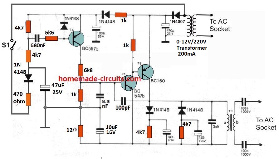
The simple transmitter circuit can be witnessed in the following diagram.
The PLC transmitter circuit includes an oscillator stage using transistors T5/T6, tuned at at 150 kHz. This oscillator frequency is switched ON through a monostable multivibrator built around T4 transistor BC557.
This monostable can be triggered using the ON/OFF switch S1. This 150 kHz frequency is then injected into the mains wiring through the transformer T1 shown at the bottom right.
So now, the 150 kHz frequency rides over the mains 50 Hz or 60 z frequency, which can be picked up by a PLC receiver unit coupled with the same wiring at a distant location or in another room.
PLC Receiver
The following image depicts the power line communication receiver circuit
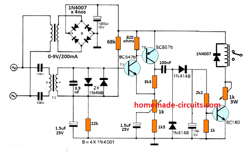
The receiver is configured around a two stage amplifier using transistors T7/T8, a rectifier circuit using two 1N4148 diodes, which has quite a long time constant.
The time delay helps to cancel out momentary interference pulses. The 150 kHz frequency is extracted through an attached transformer T2, and after suitable filtering stages, the amplifier detects and responds to the 150 kHz frequency and begins oscillating at the same rate.
The rectifier stage using the two 1N4148 and the subsequent 10 uF filter capacitor stabilizes the frequency into a stable DC for toggling ON the next relay driver transistor.
The relay driver stage switches ON the relay and the connected load, and remains ON as long as the transmitter switch S1 remains switched ON, and vice versa.
In case your neighbor might be also having a similar system installed in their house, then to avoid cross interference you may want to adjust the sensitivity of the receiver to a lowest possible setting, which may be just enough to work with your own system. This sensitivity may be tweaked with the 1 k preset.
How to Construct the Coupling Transformers T1, T2
The coupling transformers which are used for injecting and extracting the 150 kHz frequency across the mains wiring is built over 20 mm diameter pot core. The winding "b" which is towards the mains wiring has 20 turns using 31 SWG super enameled copper wire, and the side "a" which towards the circuit side has 40 turns using the same wire.
PLC Circuit using IC LM567
The above design uses a simple circuit which may perhaps get disturbed with some nearby frequency such as 140 kHz or 155 kHz, which may not seem very desirable. For achieving a pin point accuracy with the frequency response, so that the unit responds precisely to the specific transmitter signals, a PLL based IC may be required as I have explained below.
The idea was published in the datasheet of the IC LM567 as one of the application circuits, among the many other outstanding ones.
Receiver Schematic
The IC LM 567 is actually a specialized tone decoder using PLL technology which enables the device to detect and respond only to a specific frequency as determined by an external RC network values, and reject all other irrelevant frequency in the spectrum.
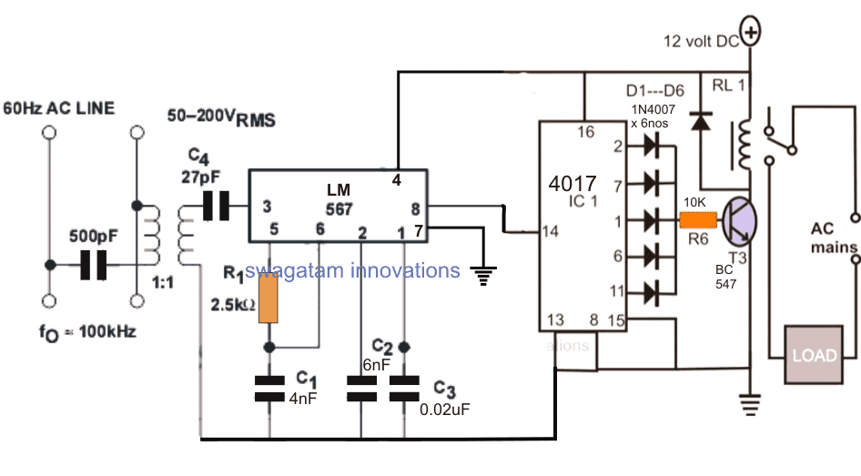
The proposed remote control circuit using power line communication may be witnessed in the above diagram, the circuit functioning details may be learned from the following points:
How it Works
R1, and C1 are the external RC components which decide the sensing frequency of the device, and pin#3 becomes the sensing pinout of the IC.
Meaning, pin#3 will detect and acknowledge only that particular frequency which is set using the R1/C1 network. For example if the R1, C1 values are selected to assign a 100kHz frequency, pin#3 will pick only this frequency to activate its output and ignore all that may be different to this range.
The above feature enables the IC to single out the specific frequency from the superimposed AC 50 or 60 Hz frequency and trigger the output only in response to this predetermined set frequency.
In the figure we can see a small isolation transformer which is included in order to isolate the electronic circuit from the lethal mains current.
The mains low AC frequency acts like the carrier frequency, over which the triggering high frequency rides to reach the intended destination across the transmission line.
In the above receiver design, the IC is assigned to respond to a 100kHz frequency which is supposed to be injected into the mains line from a nearby location which could be an adjacent room or premise.
The 100kHz frequency could be injected through any oscillator circuit such as a IC 555, or IC 4047 circuit or another IC LM567 circuit installed as the transmitter unit.
In an event when a signal is injected into the mains from a relevant location, the receiver circuit shown above detects the specific frequency in the attached mains power line, and responds to it by producing a low logic across its pin#8.
The pin#8 being connected with the a 4017 flip flop circuit toggles the output relay and the load ON or OFF depending upon the previous situation of the relay.
The Transmitter Stage
The transmitter which is supposed to inject the 100kHz or the desired triggering frequency into the power line can be ideally built using a half bridge driver oscillator circuit as shown below:
Transmitter Schematic
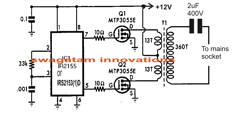
The 12V input to the circuit must be switched through a push button arrangement so that the circuit is triggered only when required in order to switch on the intended appliance through the power line.
The RC component at pin2/3 of the IC are not calculated for generating 100kHz, The following formula can be used for determining the right oscillator frequency:
f = 1/1.453× Rt x Ct
Ct is in Farads, Rt is in Ohms. and f in Hz
Alternatively the same can be evaluated using a frequency meter and with some experimentation.
This is an untested circuit designed as per the suggestions presented in the datasheet of the IC LM567.
Appliance Remote Control Circuit using AC Mains Wiring
When there are no light switches in a room, it can be difficult to install lighting without damaging the walls to add wiring for a switch. The solution mentioned involves using the power lines already in the room to control the lights remotely, without needing to add new wiring.
The transmitter
The power is, of course, directly supplied by the power grid itself through the control push button BR. The capacitive coupling is ensured by the capacitor C1.
A first alternating current (which we will call positive by convention) goes through C1 and the limiting resistor R1 to charge the capacitor C2 via D2.
The zener diode DZ1 limits the potential available on the positive plate to 12V. During the next alternating current (still negative by convention), the diode D1 shunts the power supply located downstream of D2, thus allowing the capacitor C1 to discharge (and charge in the other direction) in order to be ready to face a new cycle.
The diode D2 prevents the discharge of C2 upstream. On the positive plate of C2, there is thus a quasi-continuous, slightly undulating potential of 12V, which constitutes the power supply of the transmitter.
Finally, the resistor R2 allows the discharge of C1 as soon as the solicitation is completed. This precaution can prevent many unpleasant shocks to the imprudent operator who would inadvertently touch the connection of a component.
Modulation timebase
The NAND gates III and IV form an astable oscillator. It delivers an asymmetric square wave signal at its output due to the action of the diode D3.
The period of the signal is about 0.8 ms, corresponding to a modulation frequency of 1250 Hz. The duration of the high states of this signal is about 0.15 ms, resulting in a duty cycle of about 20%.
Carrier timebase
The NAND gates I and II form a controlled oscillator. During the low states on input 2, the oscillator is blocked. However, as soon as this input is subjected to a high state, a square wave signal with a period of about 10 us, or 100 kHz, is generated at the output. This signal serves as the carrier wave.
Amplification and transmission The signal from the output of the NAND gate II is power-amplified by the transistor T, which has the limiting resistor R9 in its collector circuit.
Thanks to the coupling ensured by the capacitor C5, the amplified signal is injected into the 220V distribution network. The zener diode DZ2 protects the transistor T from any possible overvoltage from the power grid.
Receiver
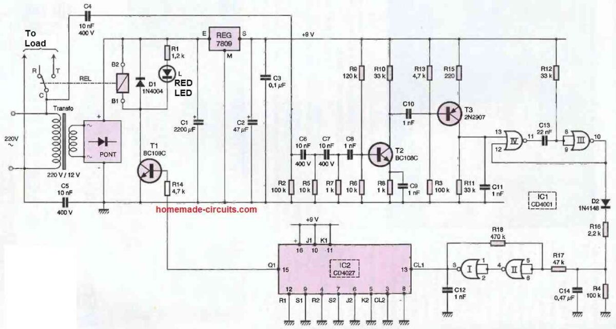
This has a completely classic power supply. The power comes from the mains via a transformer that delivers a potential of 12V on its secondary winding.
A bridge of diodes rectifies the two alternations and C1 performs a first filtering. On the output of the 7809 regulator, a stabilized DC potential of 9V is obtained. Capacitor C2 completes the filtering and C3 acts as a decoupling capacitor.
Remote Control Signal Detection
Capacitors C4 and C5 couple the low voltage part of the receiver to the mains. The signal is then taken into account by an RC filtering network consisting of the set R2, R5, R7, C6, C7.
The NPN transistor T2 is mounted in a common emitter configuration. It provides the necessary amplification.
Note that the emitter resistance is decoupled by C9 for better gain. In addition, it is essential to choose a class C transistor, characterized by a gain greater than 600. The thus amplified signal is available at the collector of T2.
Processing of the remote control signal
The PNP transistor T3, also mounted in common emitter configuration, is biased at its base in such a way that in the absence of an input signal, the potential at the collector level is zero.
On the other hand, as soon as the signal from the previous stage appears, a succession of positive pulses at the modulation frequency of 1.25 kHz generated by the transmitter can be observed on the collector of T3. The 100 kHz carrier has disappeared due to the filtering carried out by C11.
The NAND gates III and IV form a monostable circuit. It delivers on its output a series of high states characterized by a duration of about 0.5 ms, which are also taken into account by the integrating device constituted by D2, R16, R4, and C14.
During the high states, the capacitor C14 is charged through R16 and can only be discharged through R4, which has a much higher value.
Control of the Load relay
The IC2 reference integrated circuit contains two JK flip-flops, only one of which is used in the present application. For each high state from the trigger, the Q1 output changes state. When this output is in a high state, the transistor T1 is active.
It includes the coil of the load relay in its collector circuit. The relay, when closed, directly powers the receiver concerned by the remote control via the "common/working" contacts of the relay.
The diode D1 protects the transistor from the effects of self-induced overvoltage. When the relay is energized, the LED L signals that the receiver is powered by illuminating.
The relay coil is directly powered by the filtered 12V potential available on the positive armature of C1.
The AC wiring remote control thus operates like a remote switch: each press of the push button has the effect of alternately activating and deactivating the utilization receiver.
As a result, a permanent high state remains at the positive plate of C14 as long as the transmitter remote control push button is pressed.
This high state is then directed to a Schmitt trigger formed by the NAND gates I and II as well as by their peripheral resistances R17 and R18. This device gives the signal taken rising and falling edges with very steep slopes.


Questions & Answers
Thanks you a lot.
Tnank you very mutch.
Mike
Please, did you know any company that sells
ready made of that transmitter/receiver??
You can easily search it online, you may find many good options…
Hi Swagatam,
I am thinking of using this for controlling multiple solenoid valve for watering my farm. Please help advising me on the following:
Thank you very much for your advice!
Hi Dang,
Sorry, I don’t seem to have proper answers for your questions. All these information are not supplied in the article therefore I am clueless regarding these topics.
Okie Swagatam, thank for your response, I am thinking of using QG-130F module!
No problem Dang, all the best to you!
I need your help bro
Please ask your question, I will try to help!
dear brother,can you just explain about transformer t1 t1,the terns and wire guage please
Hi Onix,
the details are given in the article under the heading:
How to Construct the Coupling Transformers T1, T2
It seems to me a very effective method to switch on/off devices in remote control.
May you tell me where I can buy a transmitter/receiver pair, implemented on European Shuko type plugs.
Best regards.
Jose
I appreciate your interest in the above project. However, unfortunately I do not have any info regarding the source from where you can buy these items.
Hello Swagatam,
I have transformers with 600 ohm impedance with 1: 1 ratio.
Can I use them in PLC transmitter (T1) and PLC receiver (T2)?
Thank you.
Hi Giovanni,
Yes you can try it!
Hello,
Thank you Swagatam, in advance, for any information you can offer.
Would it be possible to transmit “alternate power” at 150 KHz using
a modified circuit similar to the one you propose?
To restate: The standard 110 “power” would be in use, but significant
150 KHz power {amperage} would be placed into a 110V socket at one end
of the house and received in a different 110V socket at the other end of the
house, separated from the 110V power.
Thank you Peter,
This idea looks too complex, I doubt such an idea may not be practically feasible.
Thank you for a most interesting article in the internet.
I would be glad to know if you could give me any advice regarding a small CCTV setup using mains cabling. Basically all I need is a camera and a monitor, no recorder required. I have an idea that the use of TP Links plugged into the mains sockets can be used. There is a firm called Bascom in Birmingham who do a setup, but at considerable cost. Any ideas will be appreciated.
Kind regards,
greatfully appreciated
I appreciate your question, however unfortunately I have no idea regarding how to set up a CCTV camera and its accessories.
Hi Swagatam,
I am thinking about making a coupler for command transmission. My thinking is
1. Using an opptoucoupler like MOC302x (random switch type) for isolation (this can work with xxx Khz pulse)
2. Using a coin for injecting a high frequency command to the powerline.
I dont have background on electronic at sufficient level. This is very rough though about type of safe coupler. I knew it is still far to go with this comparing to TDA5051 or other standard modems.
How do you think?
Please advice.
Hi Dang,
In this concept only a transformer can work as an isolated coupler, since it needs to induce the primary voltage to the secondary side of the transformer and to the grid. An opto-coupler might not work correctly in power line transmission concept.
Thanks Swagatam for your response! I will look at this to see how pulse can be injected into powerline!
Ngoc
No problem Dang, I hope you are able to solve it soon..
Hi Swagatam,
Thanks for sharing these designs and information – very helpful! I have built the PLC-based transmitter circuit using the IRS2153 with appropriate capacitor and resistor combination to output a 3.5KHz signal. However I am unsure what type of center tap transformer to use for connecting it to the AC mains, whether to use power transformer, signal transformer, audio transformer, etc… that will work with AC mains and the DC generated square wave frequency signal.
Is there a readily available off-the-shelf transformer that would be suitable for the PLC transmitter circuit or is it implied that this transformer must be custom built?
Thank you,
John
Thank you John,
Since the transmitter frequency is in kHz, the transformer core will need to be of ferrite material. Any ordinary E19 core based transformer should be enough for the application. I don’t think a ready made core would be available for this project.
Hi Swagatam,
Thank you for the response to my last question regarding the transformer type. One more question I have about the IC-based transmitter circuit is what is the output voltage of the injected high frequency signal? I have a receiver device that requires a frequency signal voltage of 3v injected into the AC mains, and am wondering if I need to use a buck converter somewhere in the circuit to step down or step up the injected frequency signal voltage to be 3v. I am also using MTP3055VL instead of MTP3055E.
Thank you again,
John
Hi John, Actually I don’t remember the frequency of the IC, you can easily calculate it using the given formula.
I think buck converter will not be required, instead you can use a simple audio amplifier with a volume control facility,and then use the volume control to adjust the amplitude level of the signal, meaning you can reduce the input signal to 3V or any other desired levels.
Hi Swagatam,
going through your web site I appreciate the the effort involved in hosting this very interesting site. I am a electronics hobbyist with just enough knowledge to be playing with electronic on a practical side, not much of theoretical knowledge.
Simply put , I am looking for a solution to solving my current problem and which is as follows.
I have multiple outdoor sensor lights ( four to be exact ) which come on and off on detection of an intruder the lights work fine.
Now the question is. Is there a way I can have an audible warning signal on a remote receiver located in any room of my choice without many wires ?
Hence this consideration of a PLC device Sending multiple tone signals over the mains which would distinguish the four lights in question.
Secondly is there any propriety device available in the market which I could look for or adapt or modify to achive this objective.
Awaiting your comments and response at your convenience, many thanks.
I reside in Richmond BC, Canada.
Thank you Farhad, yes that may be possible, however only one selected frequency could be allowed to be injected at a time, in the mains wire. If more than one frequencies are injected that could create problems.
I am not sure how multiple frequencies can be sent together without complications.
Sorry, I have no clues regarding any proprietary device available in the market.
Hi once again I am replying to your earlier answer as I don’t know where my answer went when I was typing earlier.
So, I am thanking you once again for you prompt and immediate response. Your earlier brings me to new question.
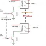
A. Can one receiver respond to multiple transmitters or senders
not being simultaneous. I guess that shouldn’t be a problem
Atall ?
B. Are the sender reciever PCB’s or gerber files available in a
kit form, and if yes where can I source them from.
Many thanks once again,
Farhad.
Hello. Swagatram, Many thanks for your quick response, I’m sorry I was unable to answer and thank you for the same earlier, somehow your response got past my observation, I’m indeed very sorry.
As regards the two circuits I plan to work on them during the winter days ahead, I look to be pretty simple, I’ll consult you if I encounter any setbacks, Thank you once. again,
Farhad.
No problem Farhad, wish you all the best!
You are welcome! Yes that seems possible. If multiple frequencies are not applied simultaneously rather one at a time, then it won’t have any problems.
Sorry we do not have the PCB layouts for this project.
Hi Swagatam,
The concept is great. I am thinking of applying your concept to develop a low speed modem circuit so devices can be linked up together using I2C protocol or a mini Mbus. Do you think that it will possible to apply your approach? Dedicated chip on the net such as ST7540 are to expensive to go! My thought is something simple:
MCU send the signal over the line
[Address off the slave to be controlled] + [Control signal: ON/OFF/QUERY_STATE] + (repeat a few time before timeout
Slave response:
[Slave address] + [Query_Result] + [END]
In this case can we use your approach to generate digital signal over the line?
Please advice with thanks
Hi Dang, it seems that might be possible, although I am not exactly sure, since I have not yet tested this circuit practically, the design was taken from one of the old reputed magazines. However sensing and receiving digital should be possible using this concept.
Hi Swagatam,
I Hope everything is well, my name is Marco and i really like the examples here provided i am working on a similar circuit and i would highly appreciate any help you could provide. i have some questions that i believe you could help me with. If you could send me an email i would appreciate it .
Thanks.
Thank you Marco, I think you can feel free to explain your queries here through comments and I will try my best to solve it for you!
Very interesting subject. Two questions: 1. How many distinct frequences could be identified in the PLC Circuit using IC LM567? Do you have any idea what the costs involved in developing and manufacturing this circuit?
I realize that the questions are quite vague.
Glad you liked the concepts. The frequency range specs of LM567 is 500 kHz maximum, so any frequency within this limit can be used.
The cost is actually very less, a lot less than $10
Dear Swagatam,
thank your reply.
I have in mind a voltage to frequency converter for the transmitter.
and frequency to voltage converter on the receiver, the receiver.
The converter frequency is carried over 50hz. as described on my first email.
I think is a challenge for you. If you need more info please let me know.
Thank you.
Dear Costas, Sorry it seems out of my scope at this moment, but I may try to figure it out more deeply when time permits.
Dear friend,
My name is Costas.
I noticed the ability you have to do almost everything.
What I like to do is:
To monitor the temp. of my water boilier located on the roof, without to run aditional wires but
using the existing power lines 240vAC/50Hz (PLC techonogy.)
1. using LM35 or I prefer NTC 10k having already sensors.
2. Range 0-100oC
3.Receiver with led or LCD display with alarm setting and output.
4. As we are under european regulation , the carrier frequency has to be between 140Khz – 148.5Khz and the maximum allowed voltage on this band is 116dbμV.
Thats all to save electricity when somebody switch on the heater and forget it.
Thank you very much.
Dear friend, thank you for liking my website.
However I do not have the idea how to show the temperature through sequential LEDs or through LCD. It can be perhaps done through a single LED and a relay cut off circuit. The relay will cut off or sound an alarm when the max temperature surpasses a threshold limit. Let me know if that’s OK with you.