The following article discusses the use of a mosfet as a switch for toggling high current loads efficiently. The circuit can be also transformed into a delay OFF circuit with simple modifications. The design was requested by Mr.Roderel Masibay.
Comparing Mosfet with BJT
A field effect transistor or mosfet can be compared with a bjt or the ordinary transistors, except one significant difference.
A mosfet is a voltage dependent device unlike BJTs which are current dependent devices, meaning a mosfet would switch ON fully in response to a voltage above 5V at virtually zero current across its gate and source, whereas an ordinary transistor would ask for relatively higher current for switching ON.
Moreover this current requirement grows higher proportionately as the connected load current increases across its collector. Mosfets on the other hand would switch any specified load irrespective of gate current level which may be maintained at the lowest possible levels.
Why Mosfet is Better BJT
Another good thing about mosfet switching is they conduct fully offering very low resistance across the current path to the load.
Additionally a mosfet wouldn't require a resistor for gate triggering and may be switched directly with the available supply voltage provided it's not far too beyond the 12V mark
All these properties associated with mosfets makes it a clear winner when compared to BJTs, especially when it's used like a switch for operating powerful loads such as high current incandescent lamps, halogen lamps, motors, solenoids etc.
As requested here we'll see how a mosfet may be used as a switch for toggling a car wiper system. A car wiper motor consumes considerable amount of current and is usually switched through a buffer stage such as relays, SSRs etc. However relays can be prone to wear and tear while SSRs can be too costly.
Using Mosfet as a Switch
A simpler option can be in the form of a mosfet switch, I have explained the circuit details of the same.
As shown in the given circuit diagram the mosfet forms the main controlling device with practically no complications around it.
A switch at its gate which can be used for switching ON the mosfet and a resistor for keeping the mosfet gate to a negative logic when the switch is in the OFF position.
Pressing the switch provides the mosfet with the required gate voltage relative to its source which is at zero potential.
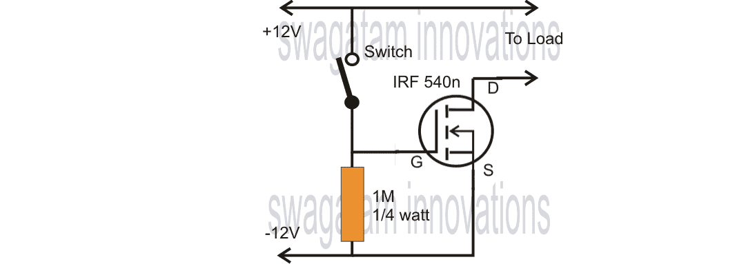
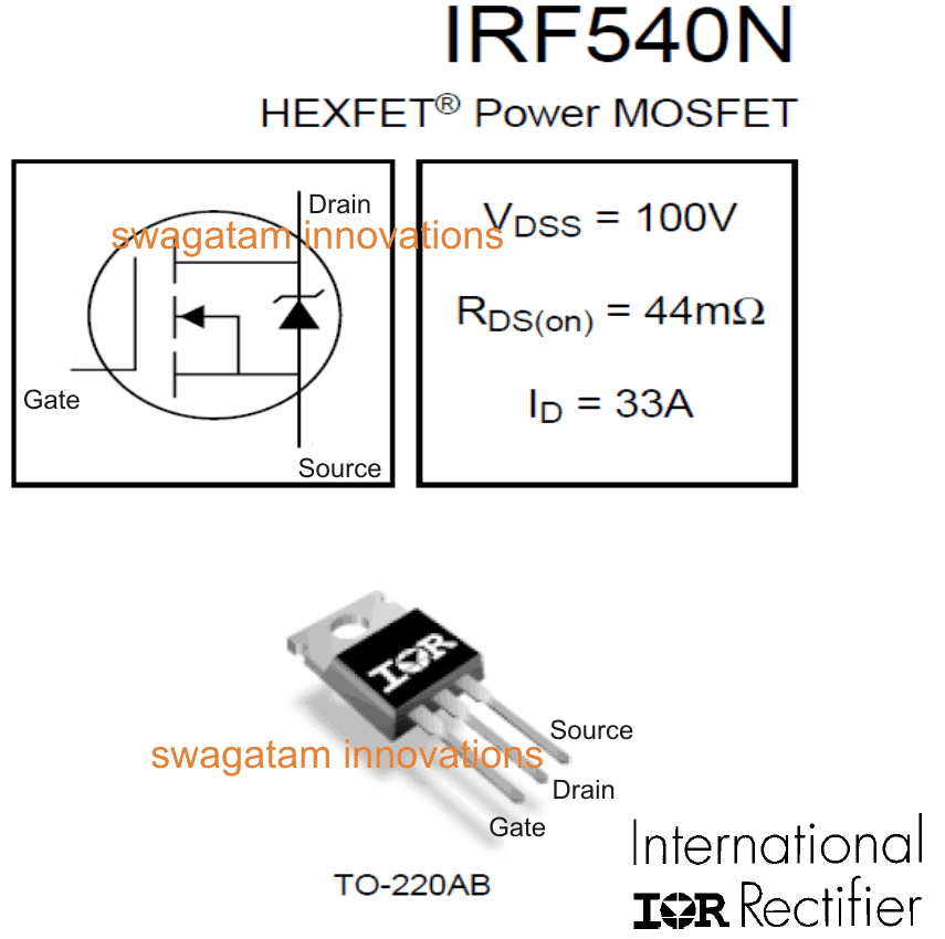
The trigger instantly switches ON the mosfet so that the load connected at its drain arm becomes fully ON and operative.
With a wiper device attached to this point would make it wipe for so long the switched remains depressed.
A wiper system sometimes requires a delay feature for enabling a few minutes of wiping action before stopping.
With a small modification, the above circuit can be simply turned into a delay OFF circuit.
Using Mosfet as a Delay Timer
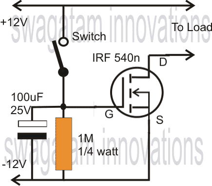
As shown in the diagram below, a capacitor is added just after the switch and across the 1M resistor.
When the switch is momentarily turned ON, the load switches ON and also the capacitor charges up and stores the charge in it.
Video Demonstration
When the switch is toggled OFF, the load continues to receive the power since the stored voltage in the capacitor sustains the gate voltage and keeps it switched ON.
However the capacitor gradually discharges via the 1M resistor and when the voltage drop below 3V, the mosfet is no longer able to hold, and the complete system switches OFF.
The delay period depends on the value of the capacitor and the resistor values, increasing any one of them or both increases the delay period proportionately.
Calculating the Delay
To calculate the delay produced by the RC constant we can use the following formula:
V = V0 x e(-t/RC)
- V is threshold Voltage at which the mosfet is supposed to just switch OFF or just begin turning ON.
- V0 is the supply voltage or the Vcc
- R is the discharge resistance (Ω) which is connected parallel to the capacitor.
- C (Capacitor Value (F) in the exemple 100uF)
- t (time of discharging that we want to calculate (s) )
we want to know the delay (t) = e(-t/RC) = V/V0
-t/RC = Ln(V/V0)
t = -Ln(V/V0) x R x C
Example Solution
If we select the threshold capacitance turn ON/OFF value of the mosfet as 2.1V, and supply voltage as 12V, resistance as 100K, and capacitor as 100uF the delay after which the mosfet will turn OFF could be approximately calculated by solving the equation as given below:
t = -Ln (2.1/12) x 100000 x 0.0001
t = 17.42 s
Thus from the results we find that the delay will be around 17 seconds
Making a Long Duration Timer
A relatively long duration timer may be designed using the above explained mosfet concept for switching heavier loads.
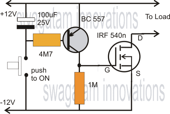
The following diagram depicts the procedures of implementing it.
The inclusion of a extra PNP transistor and a few other passive components enables the circuit to produce higher duration of delay period. The timings may be suitably adjusted by varying the capacitor and resistor connected across the base of the transistor.
MOSFET and SCR Timer Circuit
The MOSFET/SCR timer features a constant-current source to charge C1. C1 and P1 adapt the time range.You are able to adjust C1 throughout a range of 100 and 1000 uF to modify the time period range. Using a 1 ampere relay you are able to control AC loads as much as 100 watts hooked up to the 1 17 VAC or 220 V mains AC.
To use the device, wire the appliance to the relay contacts (points A and B, utilized like a switch) and alter P1 to the preferred time delay. Press S2 do discharge C1 entirely . Then switch ON S1 to begin. Soon after the set time delay has lapsed, the relay will change state, causing the load to switch ON.
On the other hand, if you have selected NC contact of the relay you are able to switch OFF the connected appliance after the set delay is over. To reuse the unit you have to press S2 to discharge C1 prior to starting.
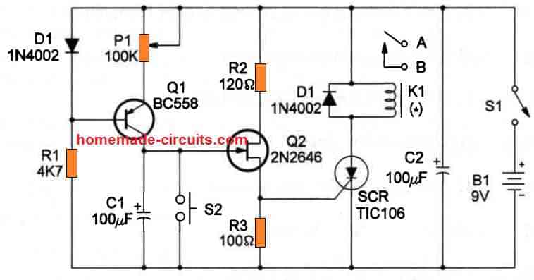
The diagram above shows basic MOSFET timer circuit.
How it Works
When power is switched ON C1 grounds the FET gate, keeping it switched OFF. Q1 acts like a constant current source, and begins slowly charging C1 at a steady constant current rate. The rate of charging of C1 is determined by the resistance of the pot P1. As soon as C1 charges to the Vgs(th) value of the FET, the FET turns ON, and switches ON the SCR, relay and the load.
The time taken by the C1 to reach the Vgs(th) value of the FET is determined by its own value and the resistance of the adjusted pot P1.



Questions & Answers
Hi,
Can you please explain why the the 1M ohm resistor is needed? In other mosfet switch sample circuits, people are using 2.2K or 10K or even 100K resistors!
Thanks in advance
Here we have tried to apply a mosfet to work as a cheap, simple timer therefore we had to employ a 1M resistor, however in the first circuit you can use any other smaller value resistor
Hi Swagatam
Please modify the 1st circuit replacing -12V with 0V.
Hi Abu-Hafss, the (-) sign is relative to the (+) sign, just as we have marked in batteries.
A (0) sign is also correct, any of the signs may be used for indicating the negative line, but only as long as the supply is not a dual type…
Oh, got it.
I thought it is designed for dual supply.
Can i replace irf540n with irlb8721pbf ? And what value of resistor should i use?
yes you can..
Should I use same 1m resistor ?
yes will do, the value decides the delay length.
What is the maximum current in output ( load)
= to supply current
If I change the power supply voltage from 12v to 14.5v, will it affect the timer duration?
yes that might force the capacitor to charge faster reducing the delay period, you may have to increase the resistor value proportionately.
I'm currently working on one project, which I called "Digital Electronic LEGO" (DEL). This DEL consists of 2 sections: Board & Block. The block contains electronic components, and can be divided into 4 main groups: LOGIC gates (e.g AND, OR, NOT, NAND,Flip-Flop, etc.), Connector (e.g Straight, Tee, Cross, etc.), Input (e.g Switch, Pulse Generator, etc.) & Output (LED, Buzzer, 7-segment, etc.). Most blocks are of standard size with square shape (1×1). Others might be multiple of standard size (e.g 1×3, 1×4, etc.). These blocks can be arranged onto the board to build a desire digital electronic circuit, such as Up/down counter, timer, light chasing etc. easily, similar to LEGO concept. The board got 2 functions: to give power supply to the block, to provide a connection between two adjacent blocks. FYI, this DEL is an educational tools designed for young student to explore "possible" logic ideas.
At present, I don't see any products available in the market which utilize the concept as above. Have you came across of such product? I do understand that this DEL is still "on paper". Do you think it can be materialize??? Please advise.
Appreciate if you could provide your response by email to my Gmail: rahimanakmar@gmail.com
Tq.
The concept looks good and useful for the new hobbyists, however I am not sure whether or not this will attract many customers, because today with the presence of programmable boards like Arduno everybody is busy concentrating on these digital programmable boards which allow you to launch almost any desired application simply by compiling a a few lines of codes.
Agree with you. Before this, I did approach some local universities & organizations (e.g SIRIM) to introduce my "idea", but none of them are interested. The reason they gave: there's already products out there in the market.
That one I do agree. But, mine is totally different (I would say) – just imagine you can build digital circuit (e.g 4-digit key code, sequencial controller, numerical display) without involve any software/programming. Only hardware involve, which give a tangible programming – easily to explain how the circuit "works".
Anyway, thank you so much for your valuable feedback.
The "digital" justification will not hold good especially after the advent of today's easy and highly advanced microcontroller applications such as Arduino which are specialists in digital execution.
as far as technology is concerned the human psychology has always been to go for the most advanced options and not the low-tech obsolete ones, therefore your gadget will not sustain in this era.
However microcontrolers are 'helpless' without the hardware stage or the power output stage, so you can think of some alternative board that would allow the students to get a quick access to all sorts of hardware stages for a given Arduino application
Hello, I'm trying to make a light turn on for 30 seconds to 1 minute every time a button gets press or a button gets disconnected what ever is easier. Would I be able to use this circuit for that. Thank you in advance.
Hello, yes the above circuit will work, you can also try the following concept which is cheaper and more reliable:
https://www.homemade-circuits.com/2014/11/long-duration-timer-circuit-using.html
I require,
A battery operated timer to illuminate USB lights in a cycle that automatically turn on at the same time every day 6 hours on 18 hours off.
Thanks.
I think you can try the following concept
https://www.homemade-circuits.com/how-to-make-simple-programmable-timer/
Pardon my ignorance, I know nothing about circuitry! I want to use a watch battery to power a mini vibration motor when a button is pressed and for the motor to stop after a certain number of seconds if the button remains pressed. Can your mosfet timer circuit be used for this purpose?
You can use the first diagram. Replace the switch with a 100uF capacitor or any value which suits the delay requirement. Now when you switch ON power through a pressed push button the mosfet will conduct for sometime and then switch OFF.
Make sure to add a 10K resistor across the circuit +/- supply lines so that the capacitor is able to discharge when switch is released.
Hello sir.Thank you for your research.Could you please let me know if mosfet as delay timer circuit can supply with transformerless 220 v 60Hz to 12 v?
Please explain if your answer is Yes or Not.
Best regards.
vahid.
Thanks Vahid, yes you can operate the MOSFET timer through a 12V transformer, just make sure to use a full bridge rectification and a good filter capacitor for the DC.
Dear swagatam..awesome mosfet timer circuit..is it same Vout with Vin?.. I need circuit same Vout with Vin. Ive try with 555 but its drop 1.4v..is theres a circuit drop Vout from Vin maybe about mV?
Thanks..
Thanks dear Indra, yes in the above MOSFET based design if the load current is within acceptable range, the drop will be negligibly small.
Hi Mr swagatam..
Ive practice your second figure circuit (im not practice with 4060 circuit yet). i replaced transistor with z44 try with A091T npn smd too, 2Mohm and 2200uF. I reach 3-4 hour maybe more (1Mohm+4400uf about 90minutes). Ive problem that my batterys depleated or freewhell after 1-2 hour charging. please give me suggestion so my batterys keep full (should i attached any other component to it?) Pardon me for ignorance.
Thanks Indira, the battery could be deleting because of the load, not because of the MOSFET or the resistor. Can you specify what load are yo using and what is current of the battery and the load?
Thanks for reply mr.
I try your circuit for charging phone, i like your circuit because just few components. amazingly your circuit is auto V&A same as input source. I experiment it for my mom old phone (5v +-1500mA). I try to my smartphone too (5-9v 4000mA). I experiment with 680K-3Mohm (with selector in series or pararel), 1000-4400uf (pararel).. I consist to use small caps (maks 2200uf) :). If there is no other way maybe later ill try with 4060. But i hope there is a solution for it.
Thanks for your help & time Mr Swag..
Np Problem Indra! Glad you could make the circuit successfully for your application…let me know if you have any further doubts!
Good day brother.
1. From 1st figure and 2nd figure what the different reach time if same RC?
2. Iam trouble with the calculation, can you tell me what R1+R2&C to get 3 hour time if using 2nd figure.
3. Your BJT&MOSFET have different current output, what max current output from 2nd figure.
Thank you
Hi Farani, the 2nd figure will give les time delay compared to the last circuit.
But both the output will give same current because MOSFT gate is not current controlled, it is voltage controlled. Of course after some discharging of the capacitor the current may get affected.
You can test with a sample RC network, lest’s say 100K and 100uF..then you can figure other values proportionately through cross multiplication since the response is to a great extent linear.
Hi
I`m looking to make a one “switch on” power supply operate two items with a variable time between the first item starting (on the main switch) and the second item starting from the timer switching it on.
The concept is to get mini smoke generators starting to warm up when the power is switched on. Then after the delay time for the smoke to be generated a motor starts up via the delay circuit (no second manual switch). This is to operate a 1:24 scale dragster model with smoking rear wheels. Just thought it would look cool if I could make it work on one switch.
Regards
Derek
Hi, does the smoke generator needs to shut off after the preset delay?
Hi
No, I just need the delay on the motor start up and then have the smoke generators and motor run together.
Some more info that may be helpful:
I have a 12vdc supply to run the smoke generators and a butt convertor dropping that down to 6vdc for the motor supply, if it helps.
Regards
Derek
Then you can try the circuit explained under the following post:
https://www.homemade-circuits.com/simple-delay-timer-circuits-explained/
Please see the design under the title: “Delay ON Timer Circuit Working Details”
I extend my greatest thanks for your rapid response and your assistance 🙂
I have looked at the circuit suggested in the link, but from that I have a question. (Sorry)
In that circuit could R2 be replaced with a variable resistor to adjust the timing of C2`s charging and if so what range would be good or is it a suck it and see type of thing.
Again many thanks.
Regards
Derek
Happy to help!
Yes you will have confirm the right value with some trial and error, which won’t be too difficult according to me.
Hi
I checked the video ,how far its accurate for duration of about one hour,can we really work on this,I need ur suggestion
Reply
Suresh
Hi, accuracy will be good if one more transistor is included as given in the last diagram
I was going through your mosfet based timer ,is it possible to reach 15 minutes delay off,if yes how about the accuracy,in the mean time ,negative line it should be 0volts,in circuit it is mentioned it as -12volts,
15 minutes is possible using the last two circuits. The negative line is the 0V line.
Please how can I use 1 signal input to power like 5 different mosfets groups, to operate different systems
You can join the gates in common and join the sources in common, connect the individual loads on the drains, and apply the signal on the common gate.
OK thanks Sir, will the signal input be able to power several gates. Any booster?
MOSFET gates are high impedance, so the signal will not drop no matter how many mosfets are connected in parallel, however the voltage must be at least 9 v or above.
Hi.Thanks for these Timer circuits, especially with MOSFET. I need connect the +load to the Source of the N-MOSFET, as the minus (-) is permanently connected. So, do I connect the Drain to + and disconnect the Source from minus? The idea is to use a 3.7v.battery to power my Components Tester for 1 minute in case of power failure, in lieu et place of the 5v (boosted to 9v).
It’s a real pleasure to read your posts! Crystal clear!
Yes, you can connect the load in the way you suggested. This configuration is called a source follower because the gate voltage is followed and replicated at the source of the MOSFET. However a MOSFET will not work with a 3.7 V. Moreover a 3.7 V at the gate of the MOSFET will not produce any voltage at its source, as far as I think.
Hi ,
Thanks for your crystal clear reply.
Question: should I then replace the MOSFET with a PNP or NPN? My challenge is to feed the 3v to 9v step-up module with 3,7v li-ion battery and cut that battery off automatically after 1 minute or so, with a simple Timer SSR circuit.
Push-Button to On it again when desired, auto Off after a minute…
–>Just to save the idle current consumption of the Boost converter and the Components Tester that uses the 9v.
I’m a 75 years old electronics passionate, and love to make everything automatic around me.
Thanks for your dedication and blessings.
Any idea of the circuit with components values?