In this article I have explained the formula and techniques of configuring RC circuit networks for controlling the arcing across relay contacts while switching heavy inductive loads.
Arc suppression
An arc is produced across the contacts when a switch or a relay is opened. With time, this condition can wear down the contacts.
To overcome this problem, an Resistor/Capacitor or RC circuit is deployed across the contacts and safeguard them. Once the contacts are open, the applied voltage goes through the capacitor and not the contacts.
During the process, the capacitor charges up faster than the contacts opening time which eventually avoids an arc from forming across the contacts.
Inrush Current Suppression
When the contacts close, the inrush current from the charged capacitor and the supply voltage can be significantly higher than the ratings for the contacts thus causing them to worsen.
To prevent this, a resistor is introduced in series with the capacitor. It functions as a current limiter by absorbing the inrush current significantly thereby reducing the produced arc and extending the life of the contacts.
C.C Bates developed a formula for calculating the resistance and capacitance value that is required for the RC network: C = I2 /10, and Rc= Vo /[10I{1+(50/Vo)}]
The voltage induced at the contact opening can be determined by
V=IRc= (Rc/RL) Vo
- Where VO = Voltage source
- I = Load current at contact opening
- RC = Resistance of RC Snubber
- C = Capacitance of RC Snubber
- RL = Load Resistance
In our following examples we talk about the reed relay arcing issues, and try to evaluate the calculations required for designing RC networks across its contacts.
Since the principle of arcing may be the same in bigger relays also, the formulas used in reed relay could be also applied for dimensioning the RC networks for the bigger relays.
How Arcing Happens in Reed Relay Switching
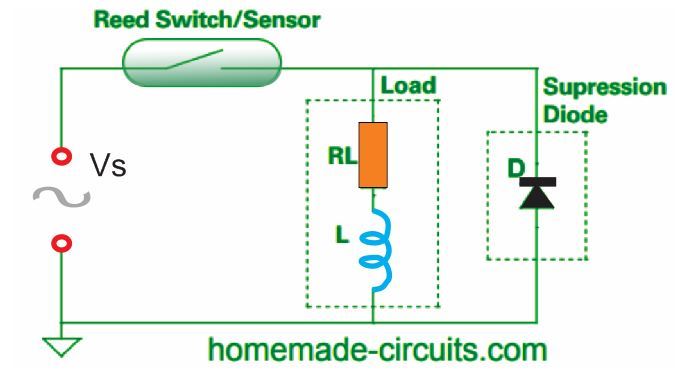
A reed switch or reed sensor can be used for controlling an inductive device like a relay coil, solenoid, transformer, small motor etc.
When the reed switch opens, the charge stored in the inductance in the device will force the switch contacts to a high voltage. Once the switch opens, the contact gap is tiny in the beginning.
Therefore, arcing between the contact gap can happen almost immediately while the switch is just opening.
The phenomenon can occur in both resistive and inductive loads, but since the latter produce a higher voltage, increased arcing activity is seen thus reducing the switch life.
A diode is normally used by the DC inductive circuits to avoid high voltage. This type of diode is called the flyback, freewheeling, or catch diode.
Unfortunately, the application of this diode is not possible in AC circuits.
So, we must use a metal-oxide varistor (MOV), a bidirectional transient voltage suppressor (TVS) diode or an RC suppression network, also known as a snubber.
These diverse arc suppression approaches have many pros and cons. Not using suppression is also an option if the relay contact life isn't affected without it.
The many factors that determines which approach needs to be undertaken, include cost, contact life, packing etc.
The fundamental reason for spark suppression circuit designs is to minimize arcing and the noise generated when engaging relays and switches.
RC Design Considerations
Using DC supply with TVS Suppressor Diode:
Using Bidirectional TVS Diode
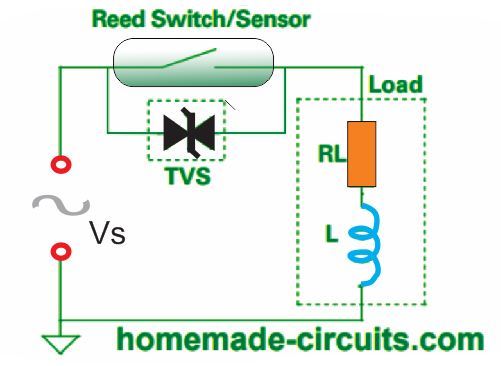
The MOV and TVS diodes conduct current when a threshold voltage is surpassed.
Normally, these diodes are connected parallel to the switch contact. Even at low voltages like 24 VAC, these devices are capable of working efficiently.
Moreover, they can also function well at higher inductance 120 VAC loads. Compared to TVS diodes, MOV devices have added capacitance.
Thus, when an MOV device is utilized, you must consider the capacitance to be used. The Hamlin application note describes this scenario better.
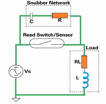
RC suppression had the edge because of limiting the switch contact voltage exactly during switch opening when the contact gap is small.
Furthermore, RC suppression can be implemented to lessen arcing and improve life in resistive loads.
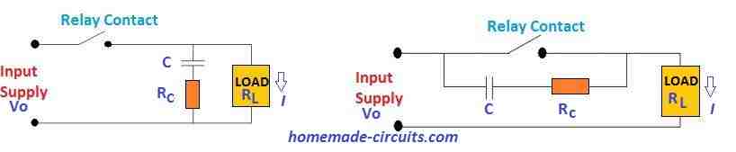
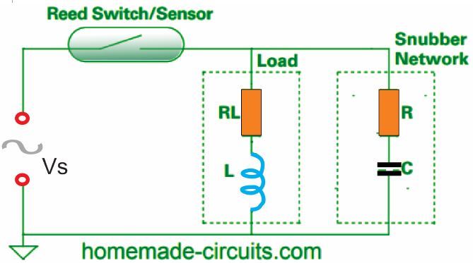
On an RC suppression circuit, a capacitor and resistor network connected in series is mounted across the switch contact in a parallel connection.
Another option is to place the capacitor and resistor across the load.
While attaching the RC snubber across the switch contact is ideal, there is a huge disadvantage because this creates a current path to the load when the switch is open.
If the snubber is installed across the load, it eliminates the current. However, changes in the connections and source impedance can affect the efficiency of the arc suppression.
Applying RC Snubber Parallel with the Switch Contact
In the snubber, the values of the resistor and the capacitor are dependent on the requirement.
The chosen resistor must have a value high enough to restrict the capacitive discharge current when the contacts of the switch close. At the same time, it must be small enough to restrict the voltage when the switch contacts open.
If you choose a large capacitor value, it will surely decrease the voltage impact while the switch contacts opens.
But larger capacitor can be expensive and might cause higher capacitive discharge energy during the time the contacts of the switch close. This type applies to both DC and AC circuits.
Using RC (Snubber) Suppression Parallel with the Load
Ohm’s law is applied to choose the most appropriate resistor value for the arc suppression.
In the Ohm's law R = V/I, we apply the formula R = 0.5 (Vpk / ISW) and R = 0.3 (Vpk / ISW), where Vpk is the AC peak voltage (1.414 Vrms) and ISW is the rated switching current of the relay contact).
To decrease the contact degradation due to arcing, we have to make sure the R value is minimum. On the other hand, the R value must be increased to lessen the relay contact arcing due to the inrush current.
Determining the value of R in between these scenarios is the challenge.
You can begin with C = 0.1μF or 100 nF, when selecting the capacitor because this is standard value and thus cost-friendly. Depending on the performance examination of this capacitor, you can increase it until the capacitance is sufficient.
There are multiple methods to assess the performance of the chosen snubber values. Some can be performed just by calculation or simulation. However, the resistive and inductive features of the load may appear indefinite.
This is largely caused by the inductance of electromechanical loads that fluctuates when the components change positions.
It is a good practice to examine the voltage waveform across the switch contacts via an oscilloscope especially during contact opening. The snubber system should alleviate or at least minimize the arcing that happens when the contacts open and close.
The increasing voltage should not restart contact arcing. Furthermore, the maximum voltage across the capacitor in the snubber must not be more than it’s voltage rating.
Yet another way to find out if the snubber is working properly for a reed switch is to look at the switch contact gap and inspect the radiance of the light produced by the arc.
If there’s less light, that means the energy generating the arc is little and therefore warrants longer life.
The final and most precise method of examining the snubber’s performance is to conduct a life test.
Contact life is directly proportional to the number of switching cycles and not to the number of powered and unpowered hours.
It is advised to keep the maximum number of operations per second for life testing of arcing loads is around 5 to 50 operations per second.
This is around 5 to 50 Hz of maximum frequency. The number of tests you can carry out is reliant on the electrical load and the difference between convenience and precision.
When you need to find out the specifications of the components for the snubber, you must consider a few other things also apart from the described inspection of arc evaluation, highest capacitor voltage and life.
It is fundamental that when a switch contact is opened, current flows through the snubber circuit.
You must ensure that this current does not cause trouble to the snubber’s application. Moreover, it is essential to confirm that the power dissipation in the snubber’s resistor does not surpass its power rating.
One more thought is that an RC snubber circuit can be utilized in combination with a bidirectional TVS diode of MOV.
An RC snubber can be a highly efficient circuitry in limiting the initial voltage across the opening relay contacts, while the TVS or MOV may be a more efficient alternative for restricting peak surge voltages.
References:
https://www.homemade-circuits.com/wp-content/uploads/2020/10/RC-snubber.pdf
https://www.homemade-circuits.com/wp-content/uploads/2020/10/spark_suppression_compressed.pdf
https://m.littelfuse.com/~/media/electronics/application_notes/reed_switches/littelfuse_magnetic_sensors_and_reed_switches_inductive_load_arc_suppression_application_note.pdf.pdf


Questions & Answers
Hello good afternoon Mr. Swagatam
This time I want to know how the snubber network is calculated since I have to control a selenoid of water load of a washing machine at 220vac with a Relay, as the washing machine works every day for many hours I want to protect the contacts of the relay with a snubber network…. But I don’t know what resistance and capacitor value I should use…. Can it be 100 OHM resistance + 100nf capacitor?. Thank you very much for your time
Good Morning Carlos,
Yes, for a 220V AC washing machine solenoid valve, a 100nF capacitor in series with a 100 ohm resistor is actually a very common and practical snubber combination.
You can connect the RC snubber directly across the relay contacts or across the solenoid coil terminals.
Normally the capacitor should be an X2-rated AC capacitor, typically:
100nF / 275VAC X2 capacitor
+
100 ohm 1/2 watt resistor
This combination works well because the capacitor absorbs the high voltage switching spikes generated by the inductive solenoid coil, while the resistor limits surge current and damps oscillations.
For most washing machine water inlet solenoids, exact calculation is usually not critical because the load current is relatively small. Therefore the standard 100R + 100nF network is widely used and should work fine in your application.
If relay sparking still persists slightly, then you may try:
150 ohm + 100nF
or
100 ohm + 220nF
But in most cases 100 ohm + 100nF is sufficient.
Also make sure the resistor is not an ordinary tiny 1/4 watt type if the relay switches very frequently. A 1/2 watt or 1 watt resistor is safer for long-term reliability.
I have a relay (SCHNEIDER ELECTRIC 8501CO16V20) for an electric heater (specs say 240 v 30 a). It’s wired with 120 on each pole.
Did I use an under-rated relay? When the relay opens there is a spark. Would one of the generic RC snubbers on Amazon work? What specs would I need to prevent this arc? I do not see any arc when it closes.
Thanks
yes, your relay is underrated, because each pole of that SCHNEIDER 8501CO16V20 relay is rated only for 16A but your heater is 30A. So even if you used both poles at 120V, still it is very close to the limit or above. Now arc is happening because when the relay opens, that big current tries to jump over air gap and causes spark. You can definitely try one of those RC snubbers from Amazon, like 0.1uF + 100 ohm rated for 250V AC and connect it across the relay contacts. It will help reduce the spark but it will not solve the underrated relay issue. For long life, better to use a relay or contactor rated minimum 30A at 240V.
Thank you so much for the replay. I didn’t realize I misread the specs on the relay. I have a contactor (ABB AF16-40-00-13 Af16 4p Contractor) arriving today. That is the same model used internally in the heater. Hopefully that will be more appropriate!
Thanks again!
Yes, looks like that should be good enough, all the best to you…
Was reading your article on snubbers on ac loads….what do you think of these generic snubbers :
I am trying to extend the life of relay contacts driving a 120Vac solenoid . I believe the values are : C= 100uF (104 J), R= 220 ohms (RED,RED,BLK),, cant read anything on varistor. .
I plan on connecting across the solenoid so not to worry about leakage current if connecting ACROSS contacts, when contacts are open….
Thx for your advice
Generic snubbers found on amazon are also good, since they include all the necessary components such as MOV, capacitor and resistor.
If the capacitor is 104, that refers to 0.1uF whose voltage rating can be 1kv.
Resistor in the image is 22 ohms 2 watt.
MOV clamping voltage rating can be anything higher 2 times the load voltage configured with the relevant contacts of the relay….
Hi Swagatam,
Thank you for your reply. I don’t think the start up current is the problem. I have the relay opened up and can see the contacts and the arcing. The main problem is the arcing when the contacts open and the circuit is drawing 6A. There is very little arcing at start up.
My predecessor in this job tried to solve the problem by using a 70A relay, but that did not solve the problem.
Have you any further thoughts?
Thank you Tom for updating the info,
In that case please try adding a 0.22uF/1kv PPC capacitor directly across the working contacts of the relay and check the response.
A direct capacitor should work more effectively than if a resistor is added in series.
Let me know how it goes?
Hi again Swagatam,
I’m only now getting around to trying this solution! I have found the following capacitor on Mouser Electronics and I’m wondering if this is the type of capacitor you are talking about?
https://www.mouser.ie/ProductDetail/KEMET/PHE844RF6220MR30L2?qs=sGAEpiMZZMsh%252B1woXyUXj%252B52UBWWIQHnz22amBc4A%2Fw%3D
Kind regards,
Tom
Thank You Tom,
I don’t think the voltage value of this capacitor would be appropriate, because it is rated at just 440V, I would recommend using at least a 1kv capacitor or a 1000V capacitor.
The 0.22uF value is fine!
Hi Swagatam,
I have an issue with a 24V DC relay, switching a 24V DC fan. The problem is the relay contacts weld shut after 6 to 8 weeks of operation. The arcing across the contacts is significant enough to cause this. The fan draws 17A on start up & 6A while running. What values of resistor & capacitor would I need to create a snubber circuit? This is an ongoing issue that I’d really like to get sorted soon. Any help from you or anyone else would be greatly appreciated.
Try reversed biased diodes at the switch and at the fan input. I would start with about 5 amp @1000PIV.
I’ve been designing industrial control >50 years. Obviously, I’ve seen this problem…a lot! You should try running electronic equipment if a 250 VDC Crane with 3000 Volt switching spikes. In that time, I have never seen this issue reduced to careful analysis. for AC, it was something like 1k and .01 uF and for DC it was a reversed bias 1N4007. Of course, this was in the generation wherein electronics was invented. So thanks for this post, I read it with great interest.
One note, regarding MOVs…When Harris began to sell these things, they were not well understood. There guys explained that each time they work, a small amount of the material is destroyed…sometimes a large amount. To determine the “health” of the MOV, they used a DC power supply in series with a DC millimeter. Slowly raising the voltage until 1mA appeared and then STOP. The present voltage rating was then known. Each time it acted on an overvoltage, the present voltage rating would decrease.
Regarding your dilemma of inrush vs collapsing field, the concept of bandwidth and filtering entered my mind, I need to think about this a bit…anyone else ??
It is therefore often essential to use a fuse in series.
Hi Tom,
It seems the start up current for your relay contacts is too high compared to the continuous current, so I don’t think a snubber would be effective in this case.
I think the only way to get rid of this problem is either to apply a slow start or a soft start for your motor, or to substantially upgrade the contact ratings of your relay so that it can comfortably handle the initial 7 amp current.
Let me know what you think about it…
Hi Swag, could you assist me with a circuit that can detect tripping of a HT line and send signal to a receiver?
Hi Stanley, can you please provide more information regarding your HT line and the type of wireless receiver you intend to use? I will try to figure out a suitable circuit….
Hello Mr Swagatam,
I have a relay in series with the B+ to 12AX7 vac tube. This arrangement
allows me with the help of a 555 timer to delay the B+ 330 vdc so as to allow the cathode to well warm up before the B+ hits it. I don’t have an arc suppression
circuit around it. The relay is rated at 1000 v surge, I’ve had no problems yet
but maybe such suppression might be a safeguard. I also have a similar arrangement for the tube heater circuit to allow the tube to heat up slowly
before the series regulators kick in. I make audio preamps with this tube
and want to extend it’s life. with such modern solid state devices I don’t want to spike anything hard, The delay is 22sec. I also have a limiting resistor on the primary side of the B+ transformer all is switched via 2 relays. I value your suggestions. Thanks, Great Lakes Audio. “I don’t have a web site yet”
Hello Mark,
Since your relay is currently not having any arcing problems, I think adding a 0.1uF/1000V capacitor directly across the switching contacts of the relay should be quite enough to safeguard it and ensure a longer life for the relay contacts.
Let me know how it goes or if you have any further issues.
Hello Swag,
I am working on an AC relay circuit (250V 10A NO). In my first version, I put an RC (100n/100ohm) across the relay contacts. Just like the second picture at the top of this page. But because of the RC I suppose, even when the relay is off, the other contact is showing 250V AC. This would mean I am bypassing the relay?
Thanks AVC, you are right, however the current would be minimal.
0.1uF would allow only around 5mA, which would be further suppressed by the 100 ohms…
If you do not want this, then you can consider adding the snubber across the load…
Thank you for the fast response! Yes I will try this hook-up.
Thanks again, A+++
Mark @ GLA audio
You are welcome, let me know if you have any further questions or doubts!
I have a DC isolation switch on the positive 12 volts of my classic car. Every few years I have to replace the switch. The premature failure I believe is caused by arching. What value resistor and capacitor do I use to create a suppressor circuit.
Hi, calculating the exact part values can be difficult, you can sort it out through some practical experimentation. Initially you can try a 100 ohm resistor in series with 0.47uF/250V PPC capacitor connected across the switch terminals and check the response.
Hi Swagatam,
The ‘reply’ button no longer works in Windows 10 so I have to reply at the top of the thread. Not sure what you mean by ‘PPC?’ Surely not Cornell Dubilier’s branding for electrolytic capacitors. Polypropylene Capacitor?
Yes, plenty of 0.01µF capacitors with high voltage rating available. My difficulty was finding them with an X2 safety rating for mains power connection. I have now ordered some X2 capacitors with 310v rating – the highest voltage I found. They are metallised polypropylene film. So hoping to make and test the new snubber arrangement across the switch this weekend.
Kind regards,
Andrew
Hi Andrew,
Yes the reply button was indeed not working, so I have reverted it back to the previous commenting platform using a plugin.
I was actually referring to Polypropylene Capacitor which should work well as long as the 310V mark is not exceeded.
If you think the relay contact arcing can exceed this limit then a X2 capacitor would be recommended.
I don’t remember the supply voltage that is being used for the motor, through the relay contacts, could you please tell me about it?
Hope the metallized polypropylene film solve the problem for you.
All the best to you.
Hi Swagatam,
The power supply to the clock motor is 230v 50Hz. Normally that is switched each minute via 10A relays in the master clock. Live 1/Live2 every other minute. The switch in the clock movement that has the contact arcing and pitting problem is a Crouzet 83 106 microswitch rated at 250v 5A. I don’t have a means to measure the max spike voltage when the contacts open.
Kind regards,
Andrew
Thank You Andrew, for updating the info
In that case 300V or 310V will not be enough, I think you should go for a 0.01uF 1 kV metallized polyester, which are quite easily available in the market and online stores.
Hi Swagatam,
The capacitors I ordered are marked X2 104K 310V ac. Do X2 rated safety capacitors have a surge rating higher than the normal marked rating? What does the 104K marking mean?
Kind regards,
Andrew
Hi Andrew,
According to the online sources the X2 capacitors are rated to handle very short voltage spikes of around/upto 2.5kV. On the other hand a 0.01uF/1kv would be able to handle constant voltages of upto 1kv.
104 indicates a 0.1uF capacitor as per my knowledge.
K indicates a tolerance of around ±10%.
I think you must cancel the order immediately, since you want a 0.01uF capacitor and not a 0.1uF…
Hi Swagatam,
Thanks for that. I’m learning lots about capacitors today! I checked the order and it is definitely for 0.01µF. The picture showed 104K, so presumably a generic picture, but I will check that when they arrive.
Regarding the safety rating, does it need to handle constant high voltages? Is it not enough to protect against short high voltage spikes? I think if the mains went to 1000v for any length of time there would be other problems with the equipment. The original clock equipment has a CE marking and I have to show that I have not compromised that. Hence the need for a safety rating on the capacitors.
Kind regards,
Andrew
Thank you Andrew,
If you are sure you have ordered the correct 0.01uF capacitor then it is fine.
Regarding the voltage rating, the 1kva constant voltage tolerance certainly makes the capacitor more resilient to wear and tear and overtime degradation compared to the ones that are designed to tolerate the peaks only for short durations, so I think if size and cost factors are not too critical I would still prefer the capacitor with constant 1kv tolerance, since it allows it to be more failproof than its X2 counterparts. However I am not sure I may be wrong with my assumption.
Hi Swagatam,
Checking the spec for X2 safety capacitors, I note they are designed to fail short circuit. Normally, this would blow a fuse and cut off the power. However, in this clock circuit it would bypass the switch and cause the motor to run continuously. So perhaps Y rated capacitors would be more appropriate as they are designed to fail open circuit. Y capacitors are more expensive, but I think they also have a higher surge rating?
Kind regards,
Andrew
Hi Andrew,
Yes, Y rated capacitors can be also used in a snubber, so you can try it.
Let me know whether it helps to solve the issue or not.
Hi Swagatam,
After some more testing, I settled on 0.01µF X2 capacitors + 1KΩ resistors in series across both terminals of the change over switch and a 0.1µF+120Ω network RF suppressor across the motor. This passed a total switched load current of 15.4mA with the motor running and 0.2mA via each snubber with the switch off. This caused a barely audible hum from the motor when switched off. The residual voltage reading on the ‘off’ side of the switch was 7v.
For long term comparison, I assembled the snubbers on one clock movement with X2 rated capacitors and the other with Y2 rated capacitors. These are supposed to withstand surges of up to 5KV
I may have been able to further reduce the current passing through the motor when ‘off’ by increasing the resistor beyond 1K or reducing the capacitor value. However, I was concerned that this may also reduce the effectiveness of the snubbers. I installed the modified circuits on site yesterday. I also replaced the switches. I last replaced them in August 2023 and the clock (with 0.47 µF suppressors) had since failed. The contacts were pitted and sooty. Anyway, all working well now. Time will tell if the switches actually last longer in service.
Many thanks for your help and advice with this problem. It has been an interesting learning experience for me. Without your guidance I don’t think I could have arrived at a working solution.
Kind regards,
Andrew
Thank you so much Andrew, for all the detailed explanations and analysis of your snubber network.
I am glad you could optimize it to the most desirable limits.
I hope it continues to work well throughout.
All the best to you, and please keep up the good work.
Hi Swagatam,
Thanks for your help with this tricky problem – much appreciated. Note messages seem have become out of date order on the board. I am replying to your message of 17th June 2024 Re: clock circuit contact arcing.
I tried a few more variations of snubbers across the switch, but they all passed sufficient current to cause the motor to hum with the switch off. 0.1µF+120Ω suppressor across the motor reduced the humming, but did not fully eliminate it. 0.020 µF capacitor or snubber across the switch reduced it to a light buzz.
So I think I will need 0.01µF or less for safe connection across the switch. I guess capacitor should also have X2 safety rating & 600v surge rating. However, I have been unable to find any for sale with that spec. The best I could find were X2 capacitors with 310v rating. Would it be ok to use those? I plan to add 300Ω resistors in series to make snubbers and further reduce the current passing through the motor when switched off. Again, I could not find 0.01µF+300Ω snubbers.
Kind regards,
Andrew
Here are the results:
1) 0.025µF+120Ω across the switch, 0.1µF+120Ω across the motor.
Total load current motor running: 15.4mA
Total load current through snubber, switch off: 1.61mA Motor Hum
Current through RF suppressor, motor running: 7.3mA
Current through RF suppressor, switch off: 0.70mA Motor Hum
2) 0.025µF+240Ω across the switch, 0.1µF+120Ω across the motor.
Total load current motor running: 13.4mA
Total load current through snubber, switch off: 1.18mA Motor Hum
Current through RF suppressor, motor running: 7.4mA
Current through RF suppressor, switch off: 0.80mA Motor Hum
3) 0.033µF+240Ω across the switch, 0.1µF+120Ω across the motor.
Total load current motor running: 13.7mA
Total load current through snubber, switch off: 1.59mA Motor Hum
Current through RF suppressor, motor running: 7.4mA
Current through RF suppressor, switch off: 0.90mA Motor Hum
4) 0.020µF across the switch, 0.1µF+120Ω across the motor.
Total load current motor running: 15.8mA
Total load current through capacitor, switch off: 1.31mA Light buzz
Current through RF suppressor, motor running: 7.4mA
Current through RF suppressor, switch off: 0.67mA Light Buzz
5) 0.020µF +120Ω across the switch, 0.1µF+120Ω across the motor.
Total load current motor running: 16.0mA
Total load current through snubber, switch off: 1.32mA Light Buzz
Current through RF suppressor, motor running: 7.38mA
Current through RF suppressor, switch off: 0.72mA Light Buzz
6) 0.020µF across the switch, 0.47µF across the motor.
Total load current motor running: 40.0mA
Total load current through capacitor, switch off: 1.00mA No Buzz
Current through RF suppressor, motor running: 34.9mA
Current through RF suppressor, switch off: 1.28mA No Buzz
7) 0.020µF across the switch, 0.47µF+47Ω across the motor.
Total load current motor running: 39.6mA
Total load current through capacitor, switch off: 1.32mA No Buzz
Current through RF suppressor, motor running: 34.8mA
Current through RF suppressor, switch off: 1.29mA No Buzz
8) Nothing across the switch, 0.47µF+47Ω across the motor.
Total load current motor running: 40.2mA
Total load current through switch, switch off: 0mA
Current through RF suppressor, motor running: 35.0mA
Current through RF suppressor, switch off: 0mA
9) Nothing across the switch, 0.47µF across the motor.
Total load current motor running: 40.2mA
Total load current through switch, switch off: 0mA
Current through RF suppressor, motor running: 34.9mA
Current through RF suppressor, switch off: 0mA
10) Nothing across the switch, 0.1µF+120Ω across the motor.
Total load current motor running: 15.8mA
Total load current through switch, switch off: 0mA
Current through RF suppressor, motor running: 7.38mA
Current through RF suppressor, switch off: 0mA
Thank you Andrew, that seems to be a lot of valuable information.
Sorry for the trouble, actually i have reverted the commenting platform to the default WordPress platform, which allows only 10 replies per thread, So after 10 replies the reply button might disappear. Kindly bear with me.
I think your motor’s ampere spec is very low, and the same could be true for the relay contacts also. It means that the switching current involved is very low, within 50 ma, as already mentioned by you.
Therefore i think the snubber network doesn’t need large capacitors, rather can work with a small value, as rightly indicated by you.
For the voltage rating, a 300V capacitor should be perfectly alright.
So you can try the 0.01µF+300Ω network, with capacitor rated at 300V or 400V (PPC).
The 300Ω does not need to exactly 300Ω, it can be any nearby value. The 0.01µF/400V PPC can be easily procured from any online store according to me.
Please let me know how it goes.