This programmable timer can be used for switching a load ON and OFF with two sets of time delays, which are programmable from 2 seconds to 24 hours independently.
The delay timings are adjustable according to the users personal specs. The ON time delay and the OFF time delay are independently settable and this facility becomes the most important feature of a programmable timer circuit.
Using Versatile IC 4060
In this page I will elucidate a very simple yet reasonably useful timer circuit diagram whose ON time and OFF time settings are independently adjustable through ordinary pots.
The idea becomes so easily configurable due to the versatile IC 4060 which require minimal number of component for getting the unit running.
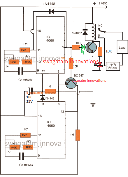
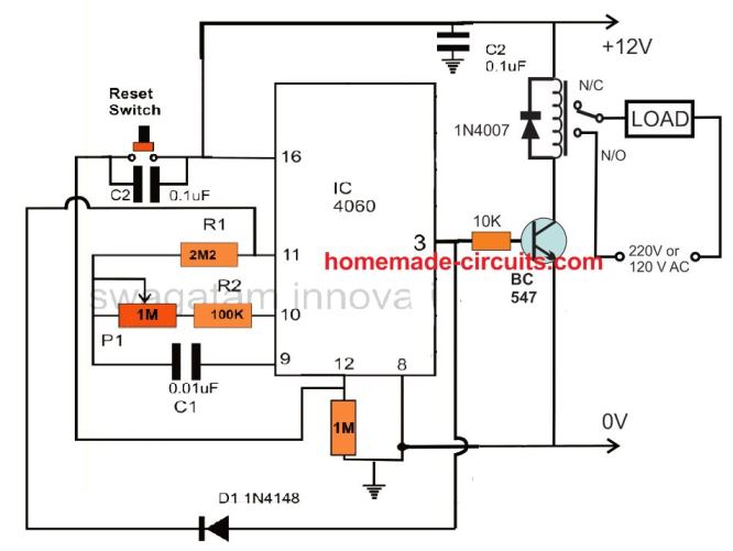
Looking at the CIRCUIT DIAGRAM below we can see that two inexpensive IC 4060 have been wired up as two independent timer modes.
However though the timing settings are independent for the two sections, these are coupled with other such that their initialization become very much interconnected.
Basically both the configurations are similar and have been rigged in the standard counting modes of the IC 4060 devices.
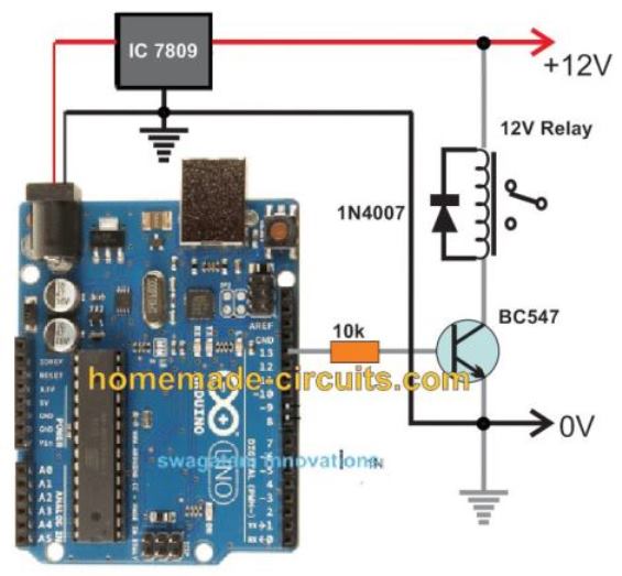
You may also want to make this Arduino based programmable timer circuit
How the Circuit Functions
The output of the upper IC is coupled to the reset input of the lower IC via a transistor in such a way that once the upper IC's output goes high, it triggers the lower timer into operation.
The lower IC then starts counting and when its output goes high, it halts the upper ICs counting and resets it to its original state and the process is initiated back from the start.
It simply means that as long as the upper ICs timing does not lapse the lower IC remains idle, however once the upper ICs timing lapses and its output becomes high, it switches the output load as well as the lower ICs operation.
The pot associated with the upper IC can be used for determining after how long the load will be switched ON, while the pot associated with the lower IC is used for determining how long the load remains in the switched ON position or simply after what time it should be switched OFF.
Update:
The LED positions have been changed in the following updated designs, because the earlier LED positions were conflicting with the relay operations, and therefore the positions have been relocated for ensuring foolproof operations.
Circuit Diagram of a Versatile Programmable Timer
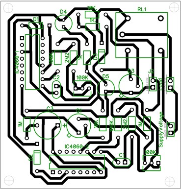
PCB Layout
Video showing the proposed 2-stage programmable timer circuit with LEDs
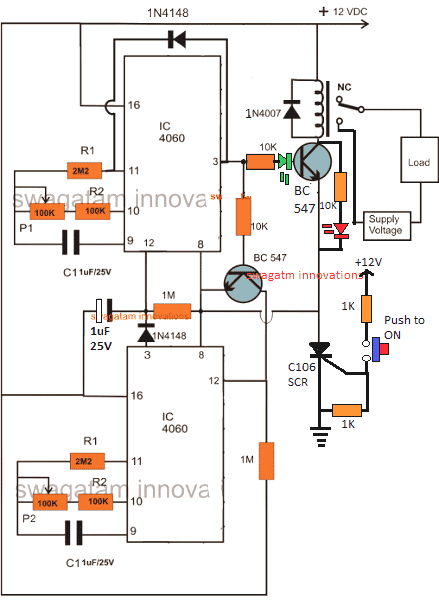
Using a Start Push-Button
The above design could be upgraded with a push-button to facilitate a push button start. This further ensures that the timer shuts off completely in case a power failure occurs while the circuit is operational, which in turn ensures that crucial loads like heater, or geyser are completely turned OFF during such situations.
Calculating RC Timing Components
It can be done through a formula, but the manual way is much simpler and accurate. It can be done as I have explained below:
- Connect any arbitrarily selected resistor above 100K in place of P1/R2 in the upper circuit.
- Switch ON and carefully note down after how much time pin#3 of upper IC 4060 becomes HIGH. This will be your "sample delay".
- Once this is noted, the other desired time delays could be calculated using the following simple cross multiplication:
Sample Delay / Desired Delay = Selected Resistor / Unknown Resistor
For example if you find the pin3 becoming high after 300 seconds, this becomes your sample delay value.
Now, we have the sample delay and the resistor value responsible for this delay.
Therefore if we assume the desired delay to be 1 hour or 3600 seconds, we can calculate it by substituting the values in the previous equation:
Sample Delay / Desired Delay = Selected Resistor / Unknown Resistor
300 / 3600 = 100 / x (unknown resistor)
300x = 360000
x = 1200 k or 1.2 Meg
This shows that 1.2 Meg in place of the P1/R2 will produce the required delay of 1 hour at pin3 of a IC 4060
Please note that the above calculation is only an example and the values do not indicate the actual results.
Customizing the Above Concept
This circuit of a flexible programmable timer circuit I have explained in this article was designed by me in response to a request by Mr.Amit. Let's know more about the request and the circuit details.
Technical Specifications
I need a circuit for my aquarium where it should do the following:
It should switch off the lights at 10:00 pm and start at 7:00 am daily + switch off the light at 12:00 pm daily and switch up at 6:00 pm back.
This will help to make my fishes live longer. 🙂
Thanks in advance.
Amit desai
The Design
So here's the circuit that I came up with. As the name suggest, the timer is pretty flexible and may be adjusted to produce any desired time periods, according to the above requested format.
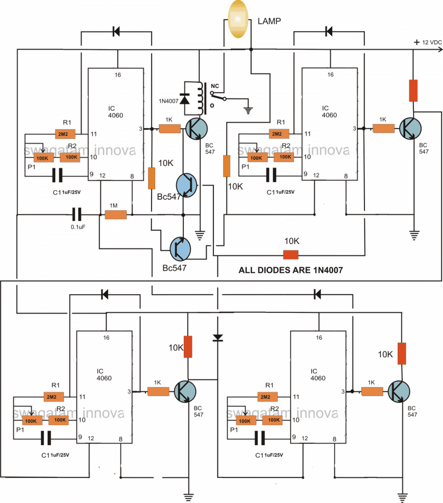
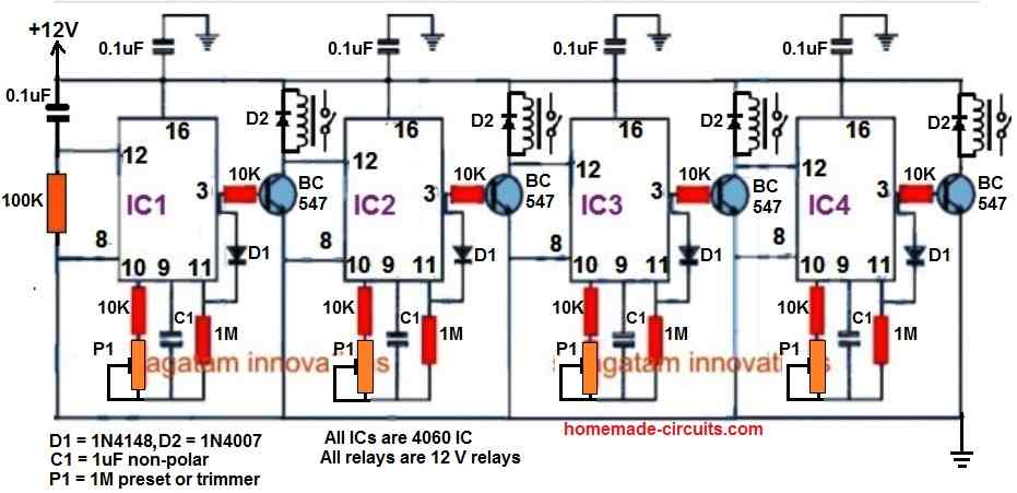
The circuit consists of four identical stages, made up of the IC 4060 timer configuration. Te timer sequence begins from the IC at the top left corner.
When power is switched ON this IC starts counting. Depending upon the setting of its pot, the IC triggers after a certain period og time interval.
This switches ON the relay and the driver transistor BC547 which consequently switches OFF the connected lamp. The stage gets latched with the help of the diode connected across its pin 3 and pin 11.
The above triggering also switches another BC547 transistor which connects the reset pin of the next IC 4060 to ground which initiates this stage also.
After a predetermined time, this IC also triggers its output at pin3 and gets latched by the corresponding diode, however this actionsends a feedback signal to the relay driver transistor, instantly switching it off and restoring power back to the lamp so that it lights up again.
Just as the above actions, the sequence further proceeds and switches ON the third IC 4060 in the line which counts the set time interval and pulls the relay back to OFF position via the diode connected to the collector of its bc547 transistor, such that the lamp again gets switched OFF.
As soon as the above triggering happens the last section at the bottom right corner switches into action and counts as per the setting of the respective pot, until the ICs output becomes high, this high reset the the first IC and switches ON the lamp once again so that the process may be restart the cycle all over again.
The pots may be increased to 3m3 for generating higher time interval periods, so is true with the respective capacitors.
Circuit Diagram
How to Adjust and Set Up
The timer may be adjusted as per the sent request, in the following manner:
If we consider the first timing sequence to begin at 7am and end at 12pm, means the upper left timer's P1 needs to be adjusted such that it activates the relay and switches off the relay after exactly 5 hours.
For keeping the lamp switched OFF in the above position and switch it ON back at 6 pm we now adjust P1 of the upper right timer section such that its output triggers after another 5 hours. This switches ON the lamp again.
The above situation needs to be kept intact until night 10pm, which is about 4 hours of period, therefore we adjust the lower right timer's P1 to get it triggered after 4 hours of time interval.
Finally, for initiating the above procedure back again the next morning at 7am, P1 of the last timer at the lower right is adjusted such that it resets the first timer after 9 hours..... and the cycle repeats.
For making the circuit work according to the above specified timing pattern, after adjusting the respective hours, the unit should be powered or switched ON exactly at 7 clock in the morning....rest will automatically follow.
Cascaded Programmable Timer Circuit with Multiple Outputs
If you are looking for a programmable timer circuit having multiple outputs for controlling multiple loads and with individual time settings, then the following circuit will do the job for you.
Here, a 4-step programmable timer circuit is shown, but you can add more number of 4060 stages to increase the number of cascaded outputs, as desired.
The time delay output of each 4060 timer stage can be individually adjusted and set using the relevant P1 preset.


Questions & Answers
can you please make a circuit which will turn on led for 10 seconds and then turn off for 10 minutes
You can try the concept which is explained in the above article using IC 4060. Let me know if you have further questions.
Buna ziua domnule.In diagrama de mai sus cu cele două 4060 programabil timer circuit, unde pot pune led pentru clipire ca în video.Multumesc fiți binecuvantat
Gelu, You can put the LED between pin#14 and ground, or pin#15 and ground, through a series 1k resistor.
Hello once again.
I must apologize to you. My first request on the programmable circuit at 2 o’clock I L’ai formulated while I had not read this second page yet. would you not consider this first request?
Joseph
Thanks
No problem Joseph, Glad you found the right post for your specific application!
hi sir, I want to 5v power supply and 1 day 2 times timer ( 6:00 am switch on to 6:15 am switch off ), (4:00 pm switch on to 4:15 pm switch off ).Please support circuit diagram with ic4060 for me.Thank you.
Hi Min,
It will require a combination of 4060 IC and 2 or 3 ICs of 4017….but still the timing durations might not be accurate.
Thank you for publishing your design. I am an electronics tech myself, and after a number of hours repairing things on my bench, I tend to leave and forget to turn off my desoldering station or power supplies.
So what I want to do, is use a circuit that has a start button , that closes a relay for an adjustable length of time, say 2-4 hours. Then opens and saves my Hakko desoldering station or my power supply’s from being on all night… or days.
A reset button would also be helpful, as some times I am down in the shop for longer than 2 hours.
Your thoughts?
Sure, that makes sense.
Here’s a simple design which will fulfill your requirement perfectly:
You can increase the timing range by increasing the value of C1 appropriately to higher values, but it should be a non-polar capacitor only.
Please ignore the previous design and use the following instead:
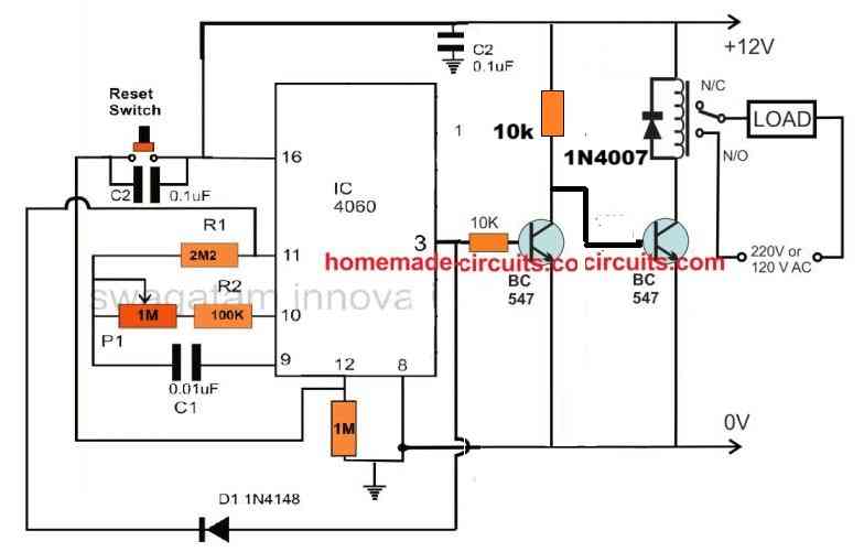
The capacitor c1 can be a 1uF/50V or higher, non-polar type.
Hi dear swgatam
Me need minimum 500 milisecond.
R1,R2 and C1 what tobe
Thanks
Hi Ismail, for a single timing output you can use a 555 timer instead.
Dont single,ı want 1 munite off 0.5 sn on for filter cleaning valve.
In the article I have provided the method to calculate the part values, please follow that procedure, you should be able to identify and select the right parts as per your specification.
Thanks dear you Are perfect
Thank you, it’s my pleasure!
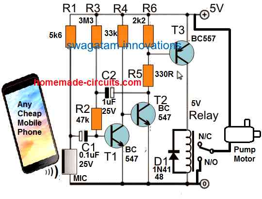
Sir, Thanks for yu patience in replying. I have got a request. I am using bore well motor having starting capacitor and running capacitor and i want to automatically switch it on. As you know that once power is given starting capacitor will be in closed circuit for 3 to 5 seconds and should disconnect after that. Is there any simple circuit which can replace the function of push button presently used?
Thank you Ravidran,
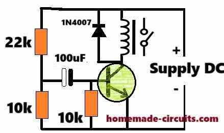
To keep the capacitor of the motor energized for a few seconds you can try implementing the following circuit:
The relay N/O contacts must be wired in series with the capacitor connection.
The 100uF capacitor and the 22k resistor values can be experimented to change the delay period as required.
The transistor can be a BC547 transistor.
This is the first time i am getting a guidance on a u tube chennal. Thanks for your quick response. I have started assembling cycles timer using CD 4060 published by you. I will make it success with your support. I do have some project. Pl share your email id.
Thank you Ravindran, i will try to help you as much as possible until you succeed.
We can comfortably discuss through this commenting platform so that other readers are also ale to go through our discussion and learn more about the subject.
Its better for me if you mention transister pin nane, like emiter collecter and base, i want to leqrn, i already maked for delay off for qs long i want, but problem is its not automatically on after 3 or 4 hrs, ppease support me……
You can checkout the BC547 datasheet below and compare the pinout details:
https://www.homemade-circuits.com/quick-datasheet-of-bc547-transistor-45v-100ma-npn-transistor/
Hello sir, hope all is going well. Sir i need your kind support. O want to diacuss about timer on and off circut. Sir can you give me a favor plz. Can you guide me resiaters, caposter valies as per cd4060 ic pin configration timing? Lile pon no 3 is for 8 to 24 hrs. Which resiaters and caposter value and pot value we have to use for same timer plz
Thanks in advance
Hello Ghulam,
There’s no accurate formula to calculate these values. You will have to find it yourself with some trial and error and using the cross multiplication formula given in the article. Please follow the steps provided under the title “Calculating RC Timing Components”
Hello sir, sorry to disturb you again. Sir, I am facing an issue in timer circuit. It works fine for almost 2 or 3 days, but after 1 or 2 or 3 days randomly it gets stuck on delay off section. I chose pin no 1 of CD4060 for delay and pin 3 for on time. 2 capacitors 22 uF as a polar capacitor I used on pin 9, 100k on pin 10 with 500k pot, and pin 11 used 2.2 mega ohm 2 resistors in series. While working, it worked fine but got stuck some time on delay section. Please guide me why it happens?
Hello Ghulam, do not use polarized capacitors. Please use only non-polarized capacitors. You can use 22nos of 1uF/100V PPC capacitors in parallel to get an equivalent 22uF non-polar capacitor.
Sir thanks for reply. Sir can i put 5mm led with 100ohm resister for pulse on pin no 7 for both ics seperatly? Or of there is any other way plz guide me
Ghulam, pin#7 will produce very fast pulse, which cannot be distinguished on the LED, instead you can use pin#15 or pin#14. Use 1k series resistor.
Its more easy if you make vedio on breadboqrf for me please.its request sir plz
Please don’t try on breadboard because breadboard can have loose connection problems, build it on a perfboard by soldering.
Dear sir, i want yo make timer for 20hrs load on and 4 hrs off. This cycle work automatically daily. Plz support me with simple diagram plz
Hello Ghulam,
The diagram is already given in the above article. You can try the first diagram.
However please do not attempt this circuit if you are a newcomer to electronics.
This circuit is recommended only for those who are reasonably expert with electronic circuits
Thanks for reply, sir i tried and its work for same time on and off, like only almost 10 seconds its on and off, i changed the resister values and pot to 1 m woth pin 10, but same. If i will not try then how i will learn, plz guide me b3cause i want to learn…..as i told you i alreqdy maked for delqy off as i want. With accurate time, but after load off not comes on automatically, i need solution for that load will on after our setting time. Plz
Hello Ghulam, The first circuit in the above article is a tested design and it worked for me perfectly.
If you are confident that you can build it then you can try the circuit step-wise. First build the upper 4060 IC stage with the BC547 and the relay as shown in the following example design. If you succeed with this, then you can add the lower 4060 stage to it and check how it works:
Yes sir i tried and this uper circut is working, now how to add 2nd ic, can you make seperate diagram plz,
Ghulam, The diagram is already given in the above article. Please see the first diagram and see how the lower IC is configured with the upper IC.
Hi sir, lot of thanks for your support. now its working, thank a lot
That’s great Ghulam, glad it is working now.
Thanks for your passion to guide me…….if some one have good teacher like you then nothing is impposible. I cleared impossible mistion due to you. Thanks a lot
You are most welcome Ghulam, Please keep up the good work!